
|
|
Forum Index : Windmills : DOUBLING FISHER an PAYKEL OUTPUT
| Page 1 of 3 |
|||||
| Author | Message | ||||
| FandPwithPVC Regular Member Joined: 09/09/2006 Location: Posts: 64 |
Hi All This method is as simple as. Hopefully Bryan will be able to do some drawings of it and get some pictures up. The MFD of the 3 unpolorised Caps we use has not been tied down and it appears that 60 MFD to 140 MFD work just as well . We use a 80 SP in Star Output. That is 3 AC wires out which have the 3 caps connected across each one of them phase to phase. We get a genuine doubling of Amps out with a very slight decrease in RPM . It is very difficult to determine if Our 5 blade Piggott notices capaciters within its operating RPM . The test bench 240 Volt Motor doesnt seem to notice it either with no increase in load amps Getting 3 Amps at 26 volts where you might have got nothing is easily achieved. Equally turning 6 Amps into 12Amps is simple.At a higher speed 10 Amps turns into 20 Amps with our Bridge Rectifiers getting hot.It defies logic why this system works so well and if there is any trade off and it is very hard to measure.Using Caps with other F and Ps will work but they will need to be matched to each unit which we will do when time permits . All For Now Regards Dennis L |
||||
| 9c12m Newbie Joined: 04/09/2007 Location: AustraliaPosts: 28 |
Hi Dennis, I had read with interest other posts on this subject so decided to try a similar configuration. I have used 2 100uF 100 volt non polarised capacitors in parallel across each pahse on a F&P 80SP. From your post I would say I have gone too big for the caps. But I did notice a votage increase and also a current increase. The attached image provides some details of the results. Cheers, 9c12m 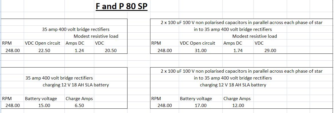 |
||||
| FandPwithPVC Regular Member Joined: 09/09/2006 Location: Posts: 64 |
Hi 9c12m . Two thing to watch out for. Firstly try to use higher voltage caps . Secondly be warned putting 17 Volts at 12 Amps into a 12 Volt battery is very dangerous. My shed has acid burns from when I did this. Put in a charge controller and limit it to 13.6 Volts. We mostly use 24 volt systems as they are better suited to F and P. Keep up the good work Regards Dennis L |
||||
Bryan1 Guru Joined: 22/02/2006 Location: AustraliaPosts: 2101 |
Hiya Guy's, Heres the schematic of the way to hookup the caps. 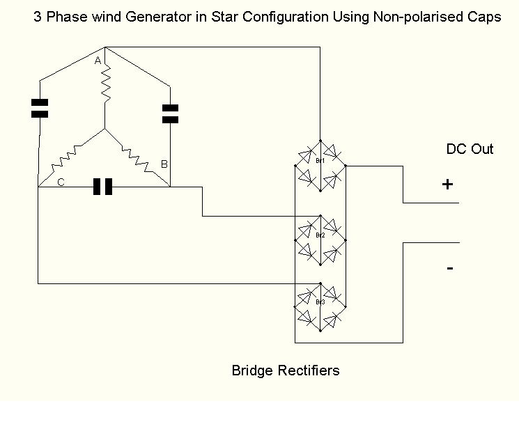
Cheers Bryan  |
||||
Highlander Senior Member Joined: 03/10/2006 Location: AustraliaPosts: 266 |
Interesting! 
What value caps would you recommend for the 7 phase? Also what's mfd? I've always measured caps in uf. Thanks Mark Central Victorian highlands |
||||
| Gizmo Admin Group Joined: 05/06/2004 Location: AustraliaPosts: 5182 |
mfp and uF are the same thing, micro farads. mfp is the older syntax, but you still see it on some modern large capacitors. Glenn The best time to plant a tree was twenty years ago, the second best time is right now. JAQ |
||||
| FandPwithPVC Regular Member Joined: 09/09/2006 Location: Posts: 64 |
Hi All Thank you Bryan for your Schematic The three non polorized caps we use are between 50MFD at 400 VDC and 145 MFD at 240 VDC. It appears the higher voltage affects the way they operate or perhaps its there large size. The 145 MFD seems to work a little better than the 50 MFD . MFD is the same as uf You will double your output on a 80SP in Star with capaciters. This a 100% guarantee with $100 being available to anyone who proves it wrong. There are many other ways of wiring caps in but the above schematic shows the best method. I have now put my money where my mouth is so give it a try. Our 5 blade Piggott easily turns 6 Amps at 26.2 Volts into 12 amps at 27.5 We continually have to use our dump load . That is in a moderate wind Regards Dennis L |
||||
| 9c12m Newbie Joined: 04/09/2007 Location: AustraliaPosts: 28 |
Hi Folks, I first tried 2 100uF non polarised capacitors in parallel (total of 200 uF) across each phase and was impressed with the results. But I then put a meter set on AC current in series with one of the capacitors (2 x 100 uf) and was surprised with a reading of 5.8 AC amps. I think that current at this level could cause over heating of the capacitors such as the cross over capacitors that I have used. So I then tried 30uF 400VAC motor start capacitors across each phase and the AC current was measured as .7 AC amps which is a significant drop. But unfortunately there was also a drop in output volatage and current. See attached image for a comparison. p.s. I only charged the battery for a few seconds to get the voltage and current readings. Cheers, 9c12m 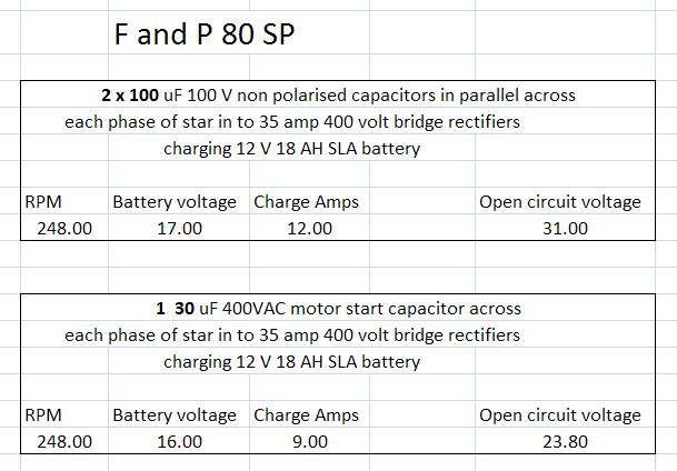 |
||||
| Highlander Senior Member Joined: 03/10/2006 Location: AustraliaPosts: 266 |
G'day Dennis,or anyone do you have any idea of what value caps to use on the 7 phase? That bloody Chalko lead me up the garden path with the 1uf caps. Mongrel poofta bastard Central Victorian highlands |
||||
| 9c12m Newbie Joined: 04/09/2007 Location: AustraliaPosts: 28 |
Hello Highlander, The F&P stator I'm using is only a 80 SP 3 phase star and I chose the 100 uF non polarised crossover capacitors from Jaycar simply because they were $5.05 each and therefore a lot cheaper than motorstart capacitors that are $12.95 each. But I did use 2 of the 100 uF capacitors in parallel which then provides 200 uF across each phase. The only reason I chose 2 in parallel was because I had read some where that heat build up could be a problem my thinking (????) was that 2 caps would have a better chance of disipating any heat. Also these caps are only 100 volt working and Dennis has suggested that perhaps a higher working voltage would be wiser. But from my comparsion with 30uF capacitors and measuring the AC current circulating through the phase capacitors it might be that the bigger capacitance then the more chance of heat build up. But the heat buildup could also be a factor of frequency, capacitance, and inductance. ?????????????????? Clearly the reasons why this works and how to select a capacitance for a particular application is way beyond me. I will do another comparsion tomorrow using just 100 uF and see what happens. The other interesting thing I have observed is that the higher the current produced heading towards the max current capability of the stator (without capacitors) then the AC circulating current in the caps reduces. Cheers, 9c12m |
||||
| FandPwithPVC Regular Member Joined: 09/09/2006 Location: Posts: 64 |
Hi All On or test bench and tower we are using 39 Capaciters from standard fluro lights. They are readily available from any junk depot and they cost us nothing as it was scrap metal. Find ones with 11uF on and put them in groups of 13 in parallel. Tidy and tie/bag them up with 2 wires coming out from each lot. Each total is 143uF. There are simpler ways of doing it but this can cost money. All for now Dennis L |
||||
| Highlander Senior Member Joined: 03/10/2006 Location: AustraliaPosts: 266 |
G'day all, in an earlier post here Megawatt Man wrote "Each combination of inductance and capacitance have a natural or "resonant" frequency at which this happens. Because the stray capacitance is small, the frequency for our F&Ps is very high, too fast for the iron to change magnetisation readily, so the energy is lost in heat in the core. Now when you use a 7 phase arrangement, the changeover between coils occurs 7/3 times more often that in a 3 phase winding, so you can expect 7/3 times the losses. So that's one of the reasons." So for the 7 phase do we need to increase uf by 7/3 (2.3)? By the way where is Mega? Haven't dropped dead have you? Central Victorian highlands |
||||
herbnz Senior Member Joined: 18/02/2007 Location: New ZealandPosts: 258 |
Hi Pleased to see this subject now separate topic. The inductance of the winding causes the stator flux to happen after the rotor flux has passed causing a reduction of output. By using capacatance it brings them in to line. The effect is more voltage output for a given speed. In all the testing above I see no measurement of input power, instead of mounting your driving motor rigid allow it to rotate and stop the rotation with a spring balance to measure the torque. input power in watts then = 2 *3.142*rpm*torque/60 torque= Kilograms *9.81 *distance to spring balance attachment to shaft centre in metres. If you do this you will get a true handle on what is happening with caps like my initial tests no caps power out 129 watts power in 165 watts eff 78 % with caps power out 196 watts power in 234 watts eff 83% both tests rpm was adjusted to the same The tests are showing that you can get small gains but really you have a method that changes the characteristic of the FP not really its efficiency. when I put my switched capacitor bank across my Hydro that is drivern by constant input power, the output has little change as i switch the various values up to 210 mfd's in out. However speed changes. You can fine tune the point where max eff is obtained but no magic doubling in real life. The tests I see above are getting increased out put but only because they changed the characteristic's at that particular RPM. I will as time permits provide a detailed test result but would rather, take time and do it correctly. Herb |
||||
| Gizmo Admin Group Joined: 05/06/2004 Location: AustraliaPosts: 5182 |
Yeah I agree Herb. While these caps change the output power, we need to measure the input power to see how its affecting efficiency. Its been mentioned that the capacitors get hot, well thats one loss we have introduced, energy is lost as heat. I remember on the New Inventers TV show a couple of years ago, this inventer changed the layout of a electric motor to use both sides of each electromagnet, and added a second row of magnets. His thinking was he had doubled the working area, used both sides of the magnets, therefore he must have doubled its efficiency. He even said it would halve the power bill. As the panel pointed out, thats wrong. Motors are already over 80% efficient, you cant have a 160% efficient motor ( oh please lets not start a discussion on free energy engines, please please ). What he had done was invent a different type of motor with different charatoristics, but would still be less than 100% efficient. Same with the F&P, they are already over 95% efficient at converting motion to electricity, we cant improve that. But we can change the charastics of this alternator, so it can make double the electrical power, but it must use double the mechanical energy to achieve this. What we need is someone with a variable speed DC motor connected to the F&P. Spin up a standard F&P, load it on a battery to get a watt figure for RPM, AND measure the driving motor current. This gives us watts in and watts out. Take measurements at different RPM's, and graph the results. Then add the caps, spin up the F&P again on the same load. Now measure the input and output watts again at the same RPM's as test 1. We can use these figures to give the efficiency of this new caps conversion. There is a chance the adding of caps may make the alternator less efficient, there would be a bit of tuning involved to get the best all rounder value of capacitance to power gain to efficiency. I do like the idea of adding caps, sure beats converting the F&P to Neo magnets, and I think we are getting the same sort of power increase for a fraction of the cost. Like Dennis said, with a bit of hunting around you could find the caps in old fluro fittings. Glenn The best time to plant a tree was twenty years ago, the second best time is right now. JAQ |
||||
| herbnz Senior Member Joined: 18/02/2007 Location: New ZealandPosts: 258 |
Hi Glen My lathe is all set up with variable speed drive (electric drill and variac ) And can support a smart drive in chuck I then stop the stator turning with balance measuring torgue speed is measured by hand tacho also I store output on stoage scope as I take measurements to check speed. I feed out put into my shed battery bank that is also suppling the Lathe so battery volts stays resonably constant also a small hydro and windmill is feeding in to make up losses. I have found it is necessary to test into a battery as resistive loads use all waveform, batteries only use peaks . along with capacitor tests I see its about time we got a relationship of number turns producing to output along with current limits when stator flux cancels out rotor flux about 240 ampere turns I believe. As regards the caps I have from my teaching days a cap bank that is three phase alowwing cap values up to 210 mfd's in 10 MFD steps. What I lack is time I have retired And find more work than ever. It amazes me how people on here can get so much done and still spend time here. Herb |
||||
| herbnz Senior Member Joined: 18/02/2007 Location: New ZealandPosts: 258 |
Hi Note above mention of motor start caps these are not continuesly rated they are in fact 2 electrolytic units with diodes for each half wave. if there is two caps on single phase motor the run one will be ok always smaller one mfd wise. Herb |
||||
| KiwiJohn Guru Joined: 01/12/2005 Location: New ZealandPosts: 691 |
Did I miss it or has there been a middling technical explanation of why/how the caps work? Are we all convinced the caps really do work as described or is it possible that the measuring indicators are being confused a little? How do digital amp meters handle peaky current, for example. Twice the output seems a little higher than what was described by the Australian university chappy who wrote a paper, the one I forget the name of and cant find anymore.  |
||||
| herbnz Senior Member Joined: 18/02/2007 Location: New ZealandPosts: 258 |
hi john I have made a few attempts to explain the stator current happens after the induced emf due to inductance windings this emf is in time with the rotor flux capacitors bring this alter this. The university chappy Dr Chalko was te first gentalman to report his input output testing results are fairly accurate considering he measured power into a drill press and subtracted loses. Using torque eliminates all those errors. he I feel lacked understanding lost my confidence when talked about poles saturating limiting current he only used 3 mfd's herb |
||||
| Highlander Senior Member Joined: 03/10/2006 Location: AustraliaPosts: 266 |
G'day John 2007-10-20_184343_SD_modification.rar I think that's what you're looking for. 2007-10-20_210649_SD_modification.zip Central Victorian highlands |
||||
| Gizmo Admin Group Joined: 05/06/2004 Location: AustraliaPosts: 5182 |
Hey Mark could you zip that up instead of rar. I know a lot of people wont have WinRar installed and wont know what to do with that file. Glenn The best time to plant a tree was twenty years ago, the second best time is right now. JAQ |
||||
| Page 1 of 3 |
|||||
| The Back Shed's forum code is written, and hosted, in Australia. | © JAQ Software 2026 |
