
|
|
Forum Index : Windmills : 7 phase F&P works first time
| Page 1 of 2 |
|||||
| Author | Message | ||||
| Tinker Guru Joined: 07/11/2007 Location: AustraliaPosts: 1904 |
Hi, today I finally got my 7 phase conversion hooked up to my lathe to see what it can put out. Quite impressive, I got 31V, 13.5A @ 550RPM which equates to a bit over 400 watts - more than I would have expected. My load resistor values were limited so I could not do a decent output graph and the old V-belt I used to drive the shaft pulley started to squeal and complain at higher RPM's. 550RPM is possibly fast enough anyway for a home made windmill, must not tempt fate here  . .
I used a bank of 14 Schottky diodes from Oatley for the rectifier. They are $1.- each and are rated 10A/60V. The short alu channel they were mounted on only got warm to the touch when I ran it for a while, delivering about 300W into the fan cooled resistor load. Now the fun begins with the propeller side of the windmill. Klaus Klaus |
||||
| GWatPE Senior Member Joined: 01/09/2006 Location: AustraliaPosts: 2127 |
Hi Klaus, You say the diodes were getting warm. At 300W you have less than 2A per phase and you are using 10A devices. Something must be wrong somewhere. I use schotkey diodes and I only derate a factor of 2 with a SMD unheatsinked. You have a derating of over 5. check the forward voltage drop [FVD] with a DMM. Unloaded my devices have a FVD of 0.16V. The same device has a FVD of 0.3V at 2A and a MAX device rating of 3A. I suspect that may not achieve the 550 rpm either as a mill. This will reduce the output volts and power proportionally. I assume the rewire is a star config, with just the 2 diodes at each end of the other winding leg. Good luck with your testing, on the bench and on the tower. cheers, Gordon. become more energy aware |
||||
| Gizmo Admin Group Joined: 05/06/2004 Location: AustraliaPosts: 5182 |
Hi Klaus Its good to see other's try the 7 phase conversion. I bet you were surprised at how little cogging there is compared to a standard 3 phase F&P. I think the 7 phase conversion is perfect for smaller windmills because it starts easily and is more efficient than a 3 phase decogged stator. Just adding to Gordons posting, try spinning the F&P with no load and see if the diodes still get warm, just to make sure the re-wire is OK. Glenn The best time to plant a tree was twenty years ago, the second best time is right now. JAQ |
||||
| Tinker Guru Joined: 07/11/2007 Location: AustraliaPosts: 1904 |
Thanks Gordon and Glenn for your comments, much appreciated. I did run up the mill with no load at first, up to 39V at 300RPM where I stopped due the 60V limit of the schottky diodes. Yes, its a star connection, as per the instructions on the 7 phase site. Two coils are connected in series and there are 3 groups of seven of those combinations in parallel. I did try to measure the diode forward drop while the load was connected but get misleading readings, dunno why, maybe because one side of the diodes is at AC potentional. Tried with digital and analogue meters, there seemed to be a ridiculous high voltage across, not making any sense. The diodes are connected in 7 pairs and a phase output goes to each pair link. All the diode + and - outputs are connected to common rails from where the output is tapped off. I will try to borrow an oscilloscope and look just what I'm getting across the diodes. When I mention getting warm above it is actually 50 degrees on the diode body, measured with a non contact thermometer. The heatsink sits at around 30 degrees. That was after running for perhaps 20 minutes. Oh, I noticed no cogging at all when the new magnet rotor was spun by hand, it was rather hard to turn with the output short circuited. I never tried the old rotor at all, have to think of a use for it now. 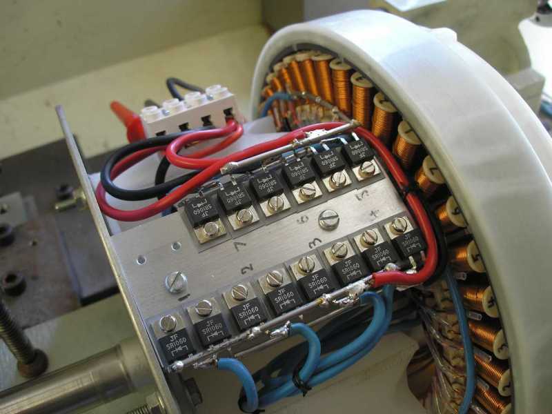 Klaus |
||||
| Gizmo Admin Group Joined: 05/06/2004 Location: AustraliaPosts: 5182 |
I think thats perfectly OK, but I could be wrong. When I was a tech we used to go by the rule that if you could hold your finger on a component for a couple of seconds then it was ok, but if you hear the sweat on your finger sizzle, its to hot. Very neat looking install. Glenn The best time to plant a tree was twenty years ago, the second best time is right now. JAQ |
||||
| GWatPE Senior Member Joined: 01/09/2006 Location: AustraliaPosts: 2127 |
Hi Gizmo and tinker, can I add a bit about sizing of pictures posted. This thread is now going to be a pain to read. Most of us reply with continuous text in paragraphs. When a picture like the one above is posted, text becomes scrolled off the RHS. Can I suggest that if readers wish to post pictures, that this, or a similar process be used. The photo from the camera, etc is displayed on the PC screen, using whatever program they prefer. As long as all the picture is visible. I will assume most readers are using a PC, sorry to the Mac or linux users. Capture the screen image with the alt+PrtSc key combination. [this copies what you see on the screen to the clipboard] Then open the Paint program. Then paste into paint. The desired area to be published is then cut with the paint cut tool. Then create a new paint window, without saving changes. Then paste the cut portion to the new page. The file should then be saved in the JPeg format. The picture can now be uploaded in a post. My photos are 5.1M on the camera, but end up 20-30k with this process and do not create the above problems. Gizmo, you may wish to elaborate some more. cheers, Gordon. become more energy aware |
||||
Bryan1 Guru Joined: 22/02/2006 Location: AustraliaPosts: 2101 |
With the screen pic's as Glenn as mentioned, I use Ifranveiw it's a free image program for winblows and I just re-size my images to 600x800dpi and they fit perfect in forum threads. |
||||
| Gizmo Admin Group Joined: 05/06/2004 Location: AustraliaPosts: 5182 |
There's a bit here in the forum FAQ. http://www.thebackshed.com/windmill/forum1/help.asp#FAQ19 I'll have to get sme of those rectifiers. I'm using the cheap DickSmith 35Amp bridge rectifiers, and I've had a few blow on a lot less than 35 amps! Glenn The best time to plant a tree was twenty years ago, the second best time is right now. JAQ |
||||
| GWatPE Senior Member Joined: 01/09/2006 Location: AustraliaPosts: 2127 |
Hi gizmo, An instruction manual. When I first started on this forum, I just previewed my post, before submitting it. This gave a good idea of what things would look like. I never went to the FAQ link, but I will see what else is there. On the topic of rectifiers, there is a 20A version in the same package from Oatley, for a good price as well. On the topic of heat. Any heat is a waste of power in a RE system. I only waste power in the components designed to do it. Resistors. Mosfets and diodes provide a lower loss when paralleled up to give a higher current rating. High speed switching does limit this benefit in some applications. cheers, Gordon. become more energy aware |
||||
| Tinker Guru Joined: 07/11/2007 Location: AustraliaPosts: 1904 |
My sincere apologies re the oversize picture posting. It WAS my first attempt to post a picture and I goofed  . .
The original was about 900Kb and I used irvanview to half its size, I'll try 600x800 next time as was suggested above. I did preview the post but on my computer this opens a seperate window about half the screen wide so its not easy to guess the pic overshoots it when seen in full size. Another question re the diodes, you may have noticed that there are two vacant spots on the heatsink. I recall that in my landcruiser manual their alternator not only has a rectified output from of the three phases but also the star point. IOW, there are 4 sets of diodes for the 3 phase output. Is it worthwhile to do the same with the 7 phase arrangement and use the star point as a rectified output as well? I'm sure the Toyota engineers used that idea for a reason, even if it escapes me just exactly why. Can anybody shed some more light on that? Klaus |
||||
| GWatPE Senior Member Joined: 01/09/2006 Location: AustraliaPosts: 2127 |
Hi tinker, you will probably find that the land cruiser used only half wave rectification. cheers, Gordon. Hey Tinker this Edit does work, This is what ericvr did to a post on me yesterday. I saw his post and started to reply. I had to chech another thread and I happened to pass the same thread and his post had changed. The spirit of a thread can get screwed up as comments that may have been made to a posted statement can now not appear. I will however leave my commentnt in above, as it was thrown in to stimulate discussion. cheers, Gordon. become more energy aware |
||||
| Tinker Guru Joined: 07/11/2007 Location: AustraliaPosts: 1904 |
No, it cetrainly does NOT use half wave rectification. AFAIK no car alternator uses half wave rectification, never heard of that idea. I said there were 4 SETS (8 alltogether) diodes connected to the + - outut points. Exactly the same way as you guys do with the half bridge rectifier per phase. Only the star point is rectified as well and connected to the output which made me wonder why. I'll try that idea anyway as soon as I get some more diodes ordered. Oh, and why did nobody suggest the simple mod of EDITING my post to fix the too large picture??? 
I just did that, too easy Klaus |
||||
| KiwiJohn Guru Joined: 01/12/2005 Location: New ZealandPosts: 691 |
Tinker, I can only imagine the connection to the star point was to produce some lower or possibly negative voltage for some electronic circuit, maybe the regulator? |
||||
Highlander Senior Member Joined: 03/10/2006 Location: AustraliaPosts: 266 |
G'day fella's, I never tried it and I have no idea if it works but this is what Nweeks wrote in another thread "It's probably best with pictures. These are on my page, but I'll link to them again here. The seven phase mod involves tying the start of seven phases together, yeah? As you can see, in the center of the pic, there's the large wire joining all the phases together. Then, you can see the diodes connected to it, which are then connected to the +ve and -ve rails. To prove that these diodes have an effect - single ones got hot, so I soldered on a second one for each polarity. The rest of the mod is the same - series connect as many phases as you want (I do three, as it allows me to have two sets of DC outputs per stator - easy quasi-delta/star connections by parallel or series of the two DC outputs)"here end quote Like I said this is nweeks work, I have no idea if it works, give it a go. That thread is here Central Victorian highlands |
||||
| Gizmo Admin Group Joined: 05/06/2004 Location: AustraliaPosts: 5182 |
You know, I think there is some gain is putting rectifiers at the star point. Need to do some research, but I do remember my auto-electrician mate commented about it a year or so ago, he said lots of the new small car alternators were adding bridges to the star point. Also I think this was covered on the Field Lines forum wher they called it "Jerry Rigged", cause it was Jerry who did the initial testing. Glenn The best time to plant a tree was twenty years ago, the second best time is right now. JAQ |
||||
| Gizmo Admin Group Joined: 05/06/2004 Location: AustraliaPosts: 5182 |
Just been looking throught the FieldLines site, I can see many posts about the Jerry Mod, but none with a simple explanation or circuit diagram. Anyone got a link to the details? Its an interresting topic and if someone can find the details we might start a new thread. Glenn The best time to plant a tree was twenty years ago, the second best time is right now. JAQ |
||||
| GWatPE Senior Member Joined: 01/09/2006 Location: AustraliaPosts: 2127 |
Hi all, I have not taken an alternator apart, but from the ample descriptions the reason seems to be. A picture will help. Firstly draw a cube in line format. Only the lines joining the corners. Now make the top square the positive and the bottom square the negative. Now place 2 diodes, end to end between each of the top and bottom corners on the top and bottom squares. Now assign the join of two diodes on one corner pair of diodes as the star point. Now draw 3, phase coils between this point and the join between each of the other diodes. This looks like a delta arrangement with one end of each phase sharing a common pair of diodes. This is an engineering solution to reduce the total number of diodes needed in a delta output arrangement. This would make a star delta conversion possible using a single, double pole single throw relay to connect the diodes at the star point to the + & - rails when the alternator was to be run in delta mode. I would think that the diodes at the star point would need to be a higher current rating though. This is anyway, How I see it. cheers, Gordon. become more energy aware |
||||
Gill Senior Member Joined: 11/11/2006 Location: AustraliaPosts: 669 |
Glenn, I have come to believe the 'Jerry Mod' referred to on the FieldLines site is what I have called IndeS and IndeP on this site. For those not familiar with these terms, it is Independently taking each coil to a bridge rectifier where the DC is then connected in Series or Parallel to give the same outputs as Star and Delta(not counting extra diode losses). This is not the same as discussed above. was working fine... til the smoke got out. Cheers Gill _Cairns, FNQ |
||||
| GWatPE Senior Member Joined: 01/09/2006 Location: AustraliaPosts: 2127 |
Hi Gill, The output voltage is not quite that simple for an alternator with a sine wave output for each phase. What you say does happen with my genny. It has a square wave output for each phase. The star voltage is 2x the independently rectified 1 phase voltage. My genny cannot be wired in the normal delta, as it has 4 phases. The phases cannot be joined end to end in a ring and rectified either. The resistance of the windings is so low and the effective duty cycle is 50%. This creates an effective short circuit in the windings. I rectify each winding independently to overcome these problems. This way, there can be no detrimental magnetic coupling between phases. With a 3 phase 120degree stator pole alignment alternator with a sine wave output the overlapping phases in star produce a rectified output voltage 1.7x the rectified output for an independently rectified phase. If you were to rectify independently and then series the 2 rectified outputs then the voltage would be doubled. Different effects happen with different numbers of phases and the spatial alignment of the phases within the stator. The greater the number of phases, the lower the rectified voltage increase seen in the star configuration. The technical side is way beyond this forum, but basically means plotting each of the AC voltage outputs of each phase on the same graph. For each angle of rotation, if you add all of the voltages + and - and then replot, the expected AC output waveform can be drawn. The peak AC voltage - diode loss will give the expected rectified voltage. cheers, Gordon. become more energy aware |
||||
| Gill Senior Member Joined: 11/11/2006 Location: AustraliaPosts: 669 |
Sorry Gordon, I'll stick to my original statement as have looked at this in detail for both 3 and 7 phase. I am more interested in the Neutral diode connection. Herb mentioned this some time back with mention of heating in it. I think his was one diode only and I couldn't see what it was suppose to achieve. Half cycle in Star, Half cycle in Delta???? Seemed odd to me. Maybe worth a search for that old thread for another look at it. Edit........ Not Herb. It must have been Nigel as linked to by Highlander. Had another look but still not sure of exactly what he'd done. was working fine... til the smoke got out. Cheers Gill _Cairns, FNQ |
||||
| Page 1 of 2 |
|||||
| The Back Shed's forum code is written, and hosted, in Australia. | © JAQ Software 2026 |
