
|
|
Forum Index : Windmills : 7 phase problem
| Page 1 of 2 |
|||||
| Author | Message | ||||
aussiekiwi Newbie Joined: 08/12/2007 Location: AustraliaPosts: 10 |
hello everyone i have just recieved my new rotor for my 7 phase smartdrive my brother and i have just finished rewiring the stator to a 2 pole star following the instuctions from this web site since rewiring we put the new rotor on to give a spin but the cogging is worse than ever both have gone back over the wiring looks to be allright can upload pictures if needed any help will be great |
||||
| martinjsto Senior Member Joined: 09/10/2007 Location: AustraliaPosts: 149 |
hi aussiekiwi, i have made a few of these now using 7p1p, 7p2p, 7p3p, all have worked great and the cogging is virtually gone, in saying that however i have made some that have cogged realy badly, upon further inspection i wired the uotputs incorectly, else i had a short look very carefully especialy around where the wires are streatcxhed to the other pole, that is where i found i had stripped the coating too far and the wires crossed and therefor shorted. they do work well sometimes i just started again and it fixed the cogging 2nd time around martin free power for all McAlinden WA |
||||
| Tinker Guru Joined: 07/11/2007 Location: AustraliaPosts: 1904 |
I second Martins suggestion that there is a wrong connection somewhere. My 7ph/3pole spins very easy by hand unloaded, very hard to spin by hand with a load 
Attached is a pic how I wired mine up. Make sure the starpoint connections are ALL at the same coil ends. 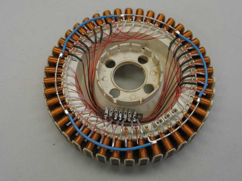 Klaus |
||||
Highlander Senior Member Joined: 03/10/2006 Location: AustraliaPosts: 266 |
G'day Tinker, It's a bit hard to see where the wires are all going but it looks like you have 2 pole fingers in series which would make it a 7 phase 2 pole, or am I misunderstanding the picture? Also it looks like you've connected the star points together, is there any reason for that? Mark Central Victorian highlands |
||||
| aussiekiwi Newbie Joined: 08/12/2007 Location: AustraliaPosts: 10 |
hello everyone thankyou for your time and help can see were we might have gone off the beaten track a bit this is my first time rewiring one of these stators could some one please explain this diagram http://www.thebackshed.com/windmill/images/stator-star.gif as this is what i have done looks nothing like the picture above |
||||
| Highlander Senior Member Joined: 03/10/2006 Location: AustraliaPosts: 266 |
Well the web link you have there is for a three phase. If you put a 7 phase magnet rotor on that there will be no output, but it shouldn't provide a huge cogg though, I recon you have a short somewhere. Can you do an ohms test between the phases? If there is a short it will show up with irregular readings between each phase. here is Glenn's instructions for 7 phase wiring. Central Victorian highlands |
||||
| Tinker Guru Joined: 07/11/2007 Location: AustraliaPosts: 1904 |
Hi Mark, We seem to use different terminology and I'm not sure who got it right  . Anyway, you saw right, there are 2 something in series and there are 3 of these in parallel on my rewired stator. . Anyway, you saw right, there are 2 something in series and there are 3 of these in parallel on my rewired stator.
edit: It seems I had the words "phase" and "group" confused, I just checked back on Glenn's description. Why would you *not* connect all the star points together? The way I understand it the current flows out of one end of a (any) coil and returns to the other end via the star point to complete the circuit. So, it flows, at any one instant, on the phase at its positive cycle part and returns via the phases on the negative cycle to the star point. There is only *one* starpoint in three phase machines and I see no reason why that does not also apply to multiphase star connected wiring. Klaus Klaus |
||||
| aussiekiwi Newbie Joined: 08/12/2007 Location: AustraliaPosts: 10 |
hello highlander thankyou for poiting that out about the diagram can see were i have gone wrong try a old rotor on it works much better will hook up some rectifiers and give a spin also now i know what diagrams to follow i will have to wire up a 7 phase next i did a ohms test does not seem to be any differents between phase |
||||
| Highlander Senior Member Joined: 03/10/2006 Location: AustraliaPosts: 266 |
|
||||
| GWatPE Senior Member Joined: 01/09/2006 Location: AustraliaPosts: 2127 |
Hi tinker, I would suggest you look at the waveform the 7phase conversion produces on an oscilloscope. This will give a hint as to why independent rectification should be employed. cheers, Gordon. become more energy aware |
||||
| Gizmo Admin Group Joined: 05/06/2004 Location: AustraliaPosts: 5182 |
I think there is some confusion on what we are calling the star point. On the photo of Tinkers 7 phase rewire ( excelent work by the way, very neat ), you can see the star points as the silver wire, there are threee of them. This is the star point that needs to be connected together. The blue wire, which is connecting the 3 star points together, is not required. But that said, there is no harm in having it there either, it cant hurt. Put simply, the three stat points in Tinkers stator will all be at the same potential, so connecting them together with the blue wires wont have any effect. eg 
is the same as 
Glenn The best time to plant a tree was twenty years ago, the second best time is right now. JAQ |
||||
| Tinker Guru Joined: 07/11/2007 Location: AustraliaPosts: 1904 |
Hi Gordon, tried the oscilloscope but it only has two traces which showed waveforms on each phase output that I expected to see. Now, if I could see all seven at once I might also see how they combine for the total AC output.
I wish you were not quite as cryptic with your comments though, its hard to get your meaning . Independent rectification??? Are 14 individual diodes "independent" enough to rectify the 7 phases? Or am I missing something important here?
regards, Klaus Klaus |
||||
| GWatPE Senior Member Joined: 01/09/2006 Location: AustraliaPosts: 2127 |
Hi Tinker, Independent rectification has a pair of diodes on each winding end. This would be 28 diodes in total. Others have suggested suitable wiring diags for 7phase. Gizmo I think used 7 bridge rectifiers. It seems the star arangement does work. Question. Was the waveform from an individual phase a good sine wave, or flattened on the top. Try and compare the shape to the output from a good audio generator. I am testing other ccts so I will have to go. Let me know the wave shape. cheers, Gordon. become more energy aware |
||||
| Highlander Senior Member Joined: 03/10/2006 Location: AustraliaPosts: 266 |
Thanks for clearing that up Glenn, and yes I was referring to the blue wire. I hadn't seen that done before. That's was what I was questioning. Central Victorian highlands |
||||
dazler Newbie Joined: 21/10/2007 Location: AustraliaPosts: 37 |
hi all new here. i am having the same problem with this clogging. i have the same clogging as new F&P to a modified one, this is the rewired i used. http://www.thebackshed.com/Windmill/images/stator-star.gif also the mill will not start up? thanks darren |
||||
| Gizmo Admin Group Joined: 05/06/2004 Location: AustraliaPosts: 5182 |
Hi Darren It looks like you may have gone down the same path as aussiekiwi. Did you buy the new magnet hub, or are you still using the old hub that came with the stator. I might have to put some more information on the web site about the different types of conversions. I know its not very clear for the beginner, a bit confusing. Glenn The best time to plant a tree was twenty years ago, the second best time is right now. JAQ |
||||
| Ayjay Newbie Joined: 16/08/2006 Location: AustraliaPosts: 10 |
Hi here is a photo of a 7 phase 2 pole conversion as per The backshed diagram,when used with the the new stator(420774P)cogging is reduced greatly.Hope photo helps cheers. 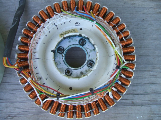 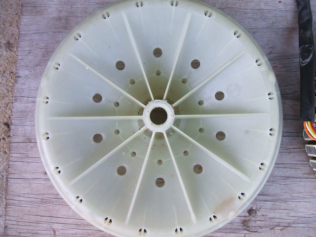 AJ  |
||||
| dazler Newbie Joined: 21/10/2007 Location: AustraliaPosts: 37 |
hi glenn i got hub with the stator. I'd look over the stator for any wrong wiring but looks good to me? also sanded back edged on fingers for less clogging?. pic 
By dazler hand spun it get 25 to 30v 2 to 3amps (max hand spun) daz |
||||
| Tinker Guru Joined: 07/11/2007 Location: AustraliaPosts: 1904 |
Hi Gordon, below are the wave forms you were interested in. First one is unloaded generator 40Vpp, 122Hz @300RPM. First and second phase shown with star point as common. 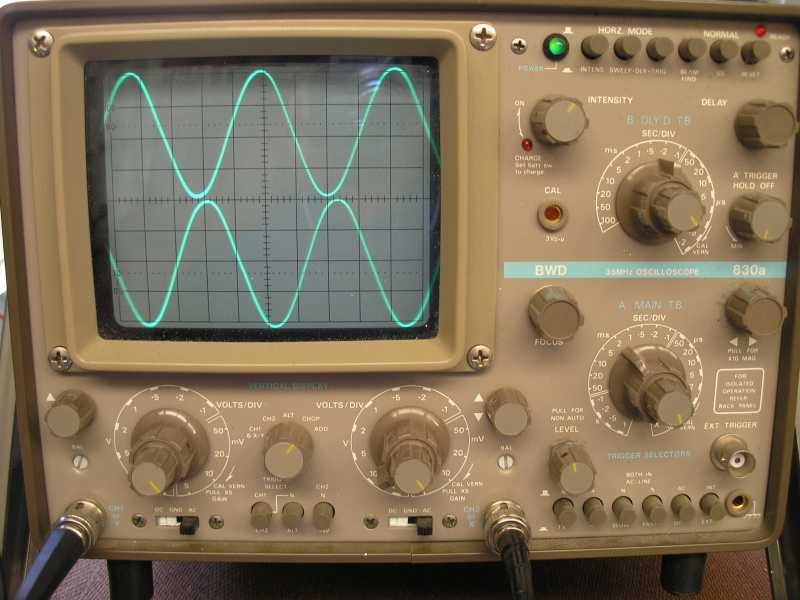
Next one is as above but loaded to 5.5A 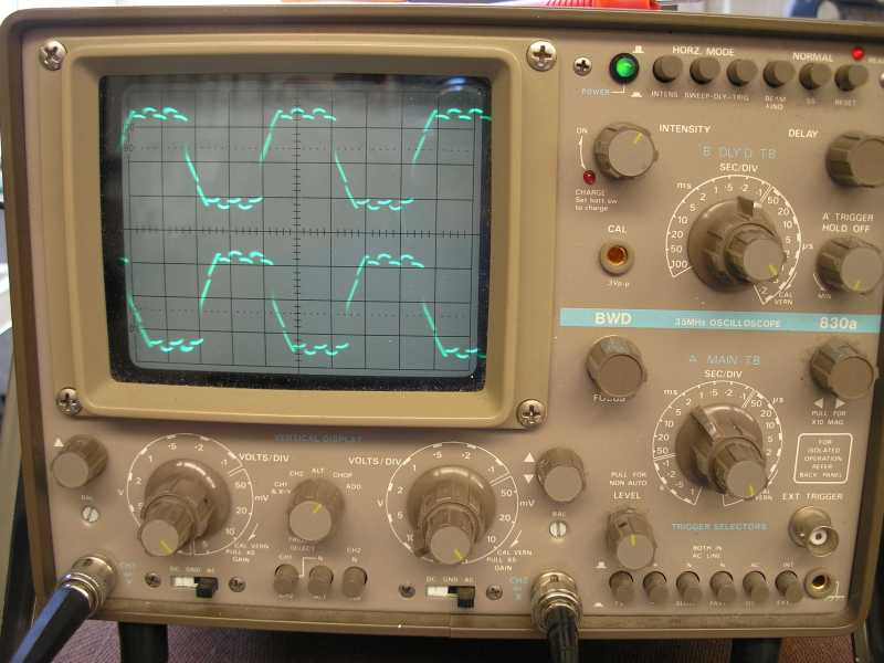
Last one is the ripple on the DC at 5.5A load ( it looks the same @ no load) 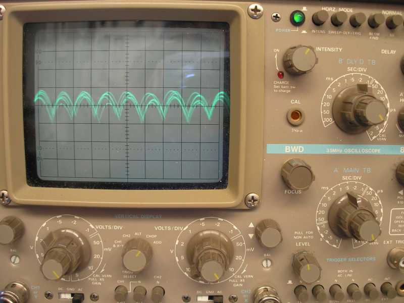
Thanks for suggesting that, the loaded trace certainly looks interesting. What do you think causes the little 'wiggles' on the squared off trace tops? And, could they be responsible why my overrated schottky diodes get warm on a heatsink? The diodes should be stone cold at that load. Klaus Klaus |
||||
| Gizmo Admin Group Joined: 05/06/2004 Location: AustraliaPosts: 5182 |
I could be wrong but I think those little squared off ripples on the top of the peaks are the rectified loads from the other phases. At the peak, the phase your looking at is taking the load, along with 3 or 4 other phases. I think you are seeing the other phases switching in and out. If you apply more load then this flat top should get wider and you should see more ripples. I think this is normal, and the same thing happens with 3 phase but its not as obvious. Its not often we come across a 7 phase AC source. But I could be wrong
Glenn The best time to plant a tree was twenty years ago, the second best time is right now. JAQ |
||||
| Page 1 of 2 |
|||||
| The Back Shed's forum code is written, and hosted, in Australia. | © JAQ Software 2026 |
