
|
|
Forum Index : Windmills : Hi-Speed Twin Sav
| Page 1 of 2 |
|||||
| Author | Message | ||||
Gill Senior Member Joined: 11/11/2006 Location: AustraliaPosts: 669 |
Here is an idea I picked off another Forum (FieldLines). It is quite good so I thought to pass it on here. The idea is to have two counter rotating savs. One driving the stator and the other driving the rotor. It doubles the speed of the generator without the power loss of a gearbox or other power loosing transmission. OK. So there is the losses of 4 bearings instead of 2, but that's bloody good for such an increase in gen speed. What's more this setup is easy to mount an F&P on to and would be about right for a 2 x 200 litre drum rig. Here's a sketch of how I see it: 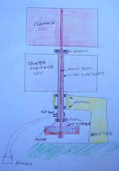
Any better thoughts?? was working fine... til the smoke got out. Cheers Gill _Cairns, FNQ |
||||
| Jarbar Senior Member Joined: 03/02/2008 Location: AustraliaPosts: 225 |
Hello Gill, I have been pursuing this idea for a few months but went cold due to the slip rings for the rotating stator.Not having any previous experience with slip rings and indications from others comments were negative regarding expense.But I have a very similar design to the above concept and if slip rings are not an issue it definitely has merit.In my version the rotor is mounted by five of the ten drain holes directly to the base of the bottom Sav.A second F&P unit could be attached similar to Glenn's HWAT twin stator setup.Which might gain the best of both the torque and increased speed. Anthony. "Creativity is detirmined by the way you hold your tounge".My Father "Your generation will have to correct the problems made by mine".My Grandfather. |
||||
retepsnikrep Senior Member Joined: 31/12/2007 Location: United KingdomPosts: 134 |
Good Idea in theory, but looks like a complicated nightmare to make. I don't like slip rings for a start. Good luck with it though. 
I'm working on my design for VAWT MK2 using 'Pig Arcs' Curved corrougated galvanised metal sheets. 
8ft Diameter x 4ft high curved sections x2 so turbine with overlap will be 12ft width x 4ft high. Be a few weeks before I can make significant progress but it's my summer project. I'll add more sections to increase height depending on output. This will be a very low speed high torque device and will be simply geared up with a cycle wheel rim under turbine with belt to a nearby LG Smartdrive. Gen1 Honda Insights. |
||||
| Gill Senior Member Joined: 11/11/2006 Location: AustraliaPosts: 669 |
Good one jarbar, I can't comment on the expense as that's a relative thing (to HER shopping plans). No reason to stick with a sav, as a lenz would do just as well or much better. I've a little difficulty understanding how it goes together with rotor screwed to one sav unless it was between them. Yes that could work. No problem making slip rings if you have lathe access. Though without it I don't think I would try this project. was working fine... til the smoke got out. Cheers Gill _Cairns, FNQ |
||||
| Tinker Guru Joined: 07/11/2007 Location: AustraliaPosts: 1904 |
That's an intersting concept Gill. I see no problems with slip rings (I do have a lathe ) but there might be a problem balancing the stator since it has to hold all the rectifiers as well securely in place. Unless you opt for 3 slip rings for three phase AC output or even 7 slip rings with the 7 phase conversion.
Would not a Lenz2 be better for this idea? Tinker Klaus |
||||
wind-pirate Senior Member Joined: 01/02/2007 Location: CanadaPosts: 101 |
Hi Gill "Some thoughts" Any thoughts to putting the stator in the middle of the mill? Could there be turbulants from the two differant directions? If the slip plates could be enclosed from the elements would they last better? THE Pirate. stealing wind & solar energy is fun |
||||
azland00123 Newbie Joined: 24/02/2008 Location: United StatesPosts: 23 |
I like the Idea, but I have had bad experiences with slip rings. The company I work for makes composite deck boards and we use slip rings for the embossers. The line only runs 14 feet per minute and if the slip ring comes loose, lets just say it is a maintenance nightmare. I cant imagine what would happen at higher speeds. If there was a way the make the wires accessible and easy to maintain, I would be all for it. Bob |
||||
| GWatPE Senior Member Joined: 01/09/2006 Location: AustraliaPosts: 2127 |
Hi Bob, AC synchronous motors have slip rings on the rotor to allow the [wound rotor] current to be altered so the power factor can be improved. These motors can operate at 1500 RPM. The bonding of the slip rings is only an engineering issue. It can be done. The slip rings and brushes should also, be protected from the weather. cheers, Gordon. become more energy aware |
||||
| Gill Senior Member Joined: 11/11/2006 Location: AustraliaPosts: 669 |
Tinker I think most VAWTS could use this system. Balancing would have to be of the shaft and all attachments (includes stator). Securely attaching rectifier is not such a drama if fitted with mounting hole or stud. Wind Pirate, Stator in the middle mentioned already. With the torque of these VAWTS, why not fit one in middle and on the bottom of the same mill? Ideal for Glen's dual staggered winding giving early cut-in as well as a high speed generation? I can't see any great turbulence issues. Certainly none in the order of counter rotating propellers or helicopter rotors. That's why I don't see this as having any potential with HAWTS. Any weather protection will improve rely ability, but there are limiting factors(none of my mills will run in the shed. ha.ha.) Bob, Many proven techniques (slip rings) can be porly designed or manufactured when utilised in specific equipment. As Gordon advised, it is a standard method on much higher rpm motors than we run VAWTS at. There is nothing wrong with the idea when it is correctly made. All vehicle starter motors run heavy brushes on to a commutator and a commutator with its gaps and arcing is much more severe than any smooth slip ring. All, There's likely 100's of ways to build a VAWT incorporating this counter-rotating idea. The engineering is just a little more involved than the beginner builder might handle, but the improved speed for power generation with such a minimal loss of torque has got to be a worth while project. Indeed the slight frictional loss from torque will be more than compensated for by a cut-in at 1/2 the former wind speed due to the 2 x higher gen rpm. I like it! was working fine... til the smoke got out. Cheers Gill _Cairns, FNQ |
||||
MyCattMaxx Newbie Joined: 24/02/2008 Location: United StatesPosts: 8 |
Car alternators have been using slip rings for decades. I have hacked alt slip rings and brushes several times. |
||||
| Tinker Guru Joined: 07/11/2007 Location: AustraliaPosts: 1904 |
Yes, and they turn at about three times the crank speed as well. Waaaay faster than any wind generator. The original car alternator brushes would carry only a few Amps field current in service. For higher current capacity brushes, those in the starter motor could perhaps be adapted to fit. Or brushes from hand held power tools, look for brushes with a 'coppery' surface. Tinker Klaus |
||||
| Gizmo Admin Group Joined: 05/06/2004 Location: AustraliaPosts: 5182 |
Looking at the idea of counter rotating turbines. I wonder if you would need a gear set to make sure the two turbines actually "counter rotate". I mean, if for what ever reason the F&P was locked up or shorted, then the top and bottom turbine will be mechanically connected and as the top turbine should have more power ( better wind ) then the bottom turbine will be forced to go backwards. Now take this back a bit and use a lightly loaded windmill, and in theory the bottom turbine will spin slower than the top. I dont know if this is a problem, but I think there may be a issue with making sure the F&P is actually spinning at double the speed. At certain loads the bottom half could even be stopped altogether while the top half is running. A set of gears would stop this "wandering". But, would it be easier to use a single turbine the same size as the 2 counter rotating turbines, rotation in one direction, and a 1:2 step up gear set ( chain, toothed belt ). You would still achieve the double RPM on the F&P, remove the brushes, and not have the "possible" problem of wandering F&P RPM. I do think the idea of counter rotation is clever, but it may not be as easy as a simple 1:2 step up. Glenn. The best time to plant a tree was twenty years ago, the second best time is right now. JAQ |
||||
| GWatPE Senior Member Joined: 01/09/2006 Location: AustraliaPosts: 2127 |
Hi Gizmo, There would not be any serious problem issues with the relative speeds of the 2 sections. The stator and rotor of the F&P will still perform the energy conversion. If one section is spinning more slowly, then the total relative RPM will be less. A VAWT of the same physical size, and only spinning one way will still have the problem of wind exposure difference between the upper and lower parts. Mechanical issues with a gearing system or a counter rotating system would still be there. The losses in a step up gearbox would probably be greater, but may provide a better alternator match as any step up gear ratio can be selected. The counter rotating system I think can only give a max x2 RPM speed increase at the alternator. Tinker, I agree, the car alternator slip rings may have to operate at over 20,000RPM, and many power tools have commutator speeds in excess of 30,000RPM. Mechanical failures do happen, but I think the hundred odd RPM of a VAWT would not be a problem. cheers, Gordon. become more energy aware |
||||
| Jon Bennett Newbie Joined: 01/11/2007 Location: AustraliaPosts: 27 |
I'm with Gizmo, think a single unit of the same dimensions with a 2:1 synchronous (toothed flat) belt drive would be easier to maintain and make pretty much the same power. Unless the bottom of top unit and the top of the bottom unit were full discs there would be a fair bit of turbulence and drag as the two sections passed each other. Synchronous belts are pretty efficient and would allow fine tuning of ratio. Hope so anyway or will have to redraw my Lenz2 plans. regards jon |
||||
| azland00123 Newbie Joined: 24/02/2008 Location: United StatesPosts: 23 |
I agree with Gordan that the relative speed would be lower. unless it was locked up then both halves would spin and no power would be generated. I wonder if they would find a balance with each other and one would drag the other around. If it did work could you set a second one on the top and have a 1:4 step up. hmmmm Bob |
||||
| Gill Senior Member Joined: 11/11/2006 Location: AustraliaPosts: 669 |
Jon, I feel not so, A single units primary drag is the frictional losses in 2 bearings. A counter rotating unit of = same dimensions has frictional losses of 4 bearings + slip rings. A single geared unit of = same dimensions has frictional losses of 4 bearings + drive belt. So assessing the two latter methods, we could not say the 4 bearings of each design has equal losses as the geared unit has the additional bearing loading of the belt tension applied to them. This more than offsets the loading of the slip ring unit. Lastly the geared unit has the frictional losses of the belt against the two drum(pulleys) and this is all extra loss to the other units. Your web site quotes losses of 2% or more. Granted there will be some added turbulence at the mid section that a single unit would not have. I just do not have the expertise to say if this would be a hindrance or benefit to it's efficiency. On well designed sav's a complete disc that protrudes past the wings, caps the ends there-by countering turbulence. Why could this not be a feature of a Lenz counter rotating unit too? Of further consideration is cogging. If an F&P has a cogging drag of 0.1kg/m, then this is the cogging drag for the counter rotating unit. However the geared unit has a cogging drag of twice this due to it's gearing, plus the excess drag above, before it will start. I appreciate your views though they be different to mine. I guess they'll stay mere oppinion until some units are made. I only wish I had the 300 years or so needed to build all the projects that inspire me. was working fine... til the smoke got out. Cheers Gill _Cairns, FNQ |
||||
| Gizmo Admin Group Joined: 05/06/2004 Location: AustraliaPosts: 5182 |
I like these discussions, the old "What If". This is one of those idea's you would need to build to see how well it works. I think it would scale down well, a couple of counter rotation savious turbines ( is the working surfaces/spinning bit of a vertical windmill still called a turbine? ) made from plastic buckets, bearings from your long forgotten roller skates, some scrap timber and a stepper motor or drive motor from a old floppy. Glenn The best time to plant a tree was twenty years ago, the second best time is right now. JAQ |
||||
| Gill Senior Member Joined: 11/11/2006 Location: AustraliaPosts: 669 |
Thanks Gordon, You've answered Gizno's doubts far better than I could have. Nothing is achieved by synchronising top and bottom speeds. These differences reflect in a single, geared unit by the SAME drop in generator speed. With this system, generator speed will always be twice the mean speed off the two rotators. No realistic situation will ever have one rotator driving the other around backwards (there by not producing power). Sorry folks especially Jon, I erred in my earlier statement that a geared single unit would have twice the cogging resistance of a counter rotating one. This is not so. In fact they will be the same unless there is a wind difference between top and bottom. In that case the geared unit will start when the mean pressure between top and bottom exceeds the cogging drag. On the counter rotating unit, It will not start until the lowest pressured unit exceeds the cogging drag. It will move backwards until it does. Fortunately, this will move it to the position where the rotator has most wind pressure on it, tending to give it a 'kick start' over the cogging drag. was working fine... til the smoke got out. Cheers Gill _Cairns, FNQ |
||||
Bergen Newbie Joined: 19/02/2008 Location: AustraliaPosts: 19 |
Hi Is anyone going to have a go at building one or doing a scale version to test the theory as I'm very interested in the unit? Looks like a great idea on paper. 
Bergen Wind powers my house |
||||
| Gill Senior Member Joined: 11/11/2006 Location: AustraliaPosts: 669 |
No takers to date. All comitted to other projects I suspect. Feel free to have a crack at it yourself. I'm sure there'd be a few interested in your progress if you did. Just make 2 of your favourite VAWT then turn one upside down. If you felt it did not live up to expectations, it could always be returned to a standard unit with 90deg staggered rotors(wings). Sound Good? was working fine... til the smoke got out. Cheers Gill _Cairns, FNQ |
||||
| Page 1 of 2 |
|||||
| The Back Shed's forum code is written, and hosted, in Australia. | © JAQ Software 2026 |
