
|
|
Forum Index : Electronics : Another Inverter Build
| Author | Message | ||||
| analog8484 Senior Member Joined: 11/11/2021 Location: United StatesPosts: 203 |
I remember that from your posts. The difference I see is the lack of the very sharp and deep divots. I think that's because your inverter is so beefy compared others. That's why I was wondering if and how the very sharp and deep but single per half cycle divots actually show in the VFB. |
||||
| KeepIS Guru Joined: 13/10/2014 Location: AustraliaPosts: 2177 |
Although the screen capture was from a 3 stack toroid, I have tested a single toroid as well and the results are almost the same. The only thing that shows up at the VFB input to the ADC is a DC voltage. Because the VFB circuit and the ACV display on the Nano cannot calculate True and Apparent power (LOW % PF) and not being true RMS detectors, they will respond the same to any load that introduces high harmonic distortion, results will be out by a few volts, AC might be 236v instead of 230v, or 224v instead of 230v, and the AC voltage display will be also be slightly out. 99% of the time it's all good, that 1% of very low PF garbage loads are not an issue, and those voltage margins have never been an issue. Not knowing the bandwidth and sampling limitations of the small DSO means the previous waveforms "may" appear completely different on a higher spec DSO. IMHO if that waveform with divots was being presented to the VFB Input terminal at the controller PCB, I doubt it would make much or any difference to AC regulation . Edited 2025-05-19 09:09 by KeepIS NANO:Inverter V 8.2ks - Linux AvrDude GUI script V4.1 |
||||
Revlac Guru Joined: 31/12/2016 Location: AustraliaPosts: 1277 |
@ analog8484 The sharp divot is just a product of the scr speed controller, I haven't seen anyone else use one regardless of the type or size of inverter, hope that helps explain it, I have added a footnote on the other page. Thanks Mike, I do like the way that this inverter just keeps going well, even when throwing this crap at it, my other HF inverters will shut off with a fault (high voltage on DC Buss) when using the heatgun on low. Will be running an Air fryer shortly.  Cheers Aaron Off The Grid |
||||
| analog8484 Senior Member Joined: 11/11/2021 Location: United StatesPosts: 203 |
That's a good point. SCR can start the phase cut anywhere in the mains cycle while the diode half wave rectifier can only start the phase cut at zero crossings. I wonder if you had adjusted the SCR to start the phase cut at/near zero crossing you would have seen a similar waveform as KeepIS did. |
||||
| Revlac Guru Joined: 31/12/2016 Location: AustraliaPosts: 1277 |
Ok, so you made me dig a little deeper....and my curiosity joined the party , after looking at the difference between the signwaves with either a diode (heatgun) on the low power settings and the speed controller running at different power levels while watching the DSO,  I suspected the speed controller is a bit more than just an ordinary SCR and a few bits, after some stuffing around I could just make out half of the part number and it turns out to be a Triac bta100-800b so it now makes more sense the way the is shows on the DSO and is easy for the inverter to run and not as hash as a diode or single SCR. I suspected the speed controller is a bit more than just an ordinary SCR and a few bits, after some stuffing around I could just make out half of the part number and it turns out to be a Triac bta100-800b so it now makes more sense the way the is shows on the DSO and is easy for the inverter to run and not as hash as a diode or single SCR.The first photo is the speed controller running a restive load at 200w the second photo is at 1700w the divot moved from one side over the peak of the wave to the other side, the inverter runs this just fine, no change in sound from the toroid and no other loads running, turn the controller all the way up and the divot is gone. 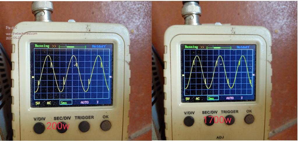 Keep in mind that some appliances have filter caps, and others have very little, with so many variables (different DSO) its a bit much to expect it to look identical to the signewave on other builds although it can look quite close. Busy with other work lately. Been thinking about making some terminal covers for the terminals on the bottom of the inverter.  Cheers Aaron Off The Grid |
||||
| KeepIS Guru Joined: 13/10/2014 Location: AustraliaPosts: 2177 |
The variable speed heatgun is pulling power from both halves of each AC cycle so the Toroid does not complain much, if at all, but those garbage heatguns that use a Diode in series for low speed, pull power from only half of each AC cycle, causing higher harmonic distortion and unbalance the AC waveform which causes the Toroid to growl. NANO:Inverter V 8.2ks - Linux AvrDude GUI script V4.1 |
||||
| analog8484 Senior Member Joined: 11/11/2021 Location: United StatesPosts: 203 |
Thanks @Revlac for doing the test. It's interesting that low and high speed controller loads caused divots with similar magnitudes. I had expected the magnitude to be proportional to overall load. But now it looks like the rate of load current change and voltage magnitude at the sine wave position likely play a bigger role. |
||||
| Revlac Guru Joined: 31/12/2016 Location: AustraliaPosts: 1277 |
Skip the story if you like. A week and a half ago I removed the 900w 230v bore pump at the top dam, its been great for years but recently its been tripping the safety switch instantly, it was doing that on the other inverters as well but sometimes it would run for an hour orso before tripping, I got around the tripping issue for a while by using an isolation transformer it runs well with that but really the pump needs fixing. A friend brought round an old pump his mate chucked out because it no longer works, its a jet pump type sits above a bore, found several problems with it, fixed most that I could see then tested the motor on the old Lister generator, first it sat and buzzed a bit, plugged it in again and it spin up to full speed.  A week later took it up to the shed connected it to the water tank with a 2 inch suction pipe and powered it up, didn't start at first tried it again and it went, tried several more times and it started perfectly each time, I had the pump running off the little old 4kw HF inverter. Recently tested the start current on the pump and it was 26Amp, the 4kwHF inverter is rated for 21Amp and I'm a bit surprised it started it then. I wanted to try the pump on this inverter as we had a sunny day it was a good time to pump some water into the top tank, connected the pump and the inverter went into over-current as soon as I switched the pump on, no worries hit the reset and its up and running again, got the old generator going again and test the pump and it would not start first time, switched it off then back on again and it run...WTF....time to see whats going on, took the end cover off the Davey pump and the capacitor wires were rubbing on the shaft, replaced the start capacitor and routed the wires around away from the shaft, assembled the pump and tested again with the generator, start current is now 27Amp, ok that's still going to trip the inverter so lets run it through the 100m cord that it will be used on at the dam, checked the start current again and it was 21Amp, I expected a bit of drop but that's significant. Read on. Ok connected to the inverter and powered up the pump perfectly well, did this about 5 times and run every time no over current trip. Took the pump to the dam and plumed it up, primed it ready to go, turned on the pump and nothing?... went up to check the inverter and it had tripped with AC under voltage (hadn't seen that before) it required a restart to clear that, after the restart the next error come up, think it said last error over current?.....reset button wouldn't reset this one so it was another restart before the inverter was back up and running properly. I'm certain I also hit PWM 99% when starting the pump before, so its maxed out the 2Kw toroid with its turns ratio Question is could I have triggered 2 errors/faults at the same time? No solar today, batteries have not charged at all, Cheers Aaron Off The Grid |
||||
| KeepIS Guru Joined: 13/10/2014 Location: AustraliaPosts: 2177 |
Yes it's possible under a really unstable load or wiring condition, you need a DSO with trigger on startup current increase, sounds like there are sudden spikes and back EMF conditions. Under voltage should not trip unless the Toroid ratio or input resistance is causing a big voltage drop. Without a DSO monitoring the inverter DC input current and voltage, then moving on to the AC output voltage, both under a trigger capture that can be reviewed in detail, we are just guessing. I have started over 25kW DC input equipment on a single toroid inverter of this type, it sounds like an unstable loss condition somewhere under high currents. It looks like the Inverter first tripped with an "over current", the first error is saved in the Nano, it could have then caught an "AC under voltage" as the AC was instantly dropped on over current, that error would be displayed when you looked at the LCD as the Nano was still powered on. On a restart the Inverter would display the first saved error (Last error over current), this is to force USER intervention (manual restart) to stop any possibility of an automatic restart under an existing bad fault condition  The real error was over current, wondering if you have Over current set a tad low? Almost none here as well, dark and raining, about 300 watts with a peak of 1.2kW for 1/2 hour, batteries running at 55%, looks like some SUN tomorrow so we will be ok overnight. . Edited 2025-06-30 15:58 by KeepIS NANO:Inverter V 8.2ks - Linux AvrDude GUI script V4.1 |
||||
| Revlac Guru Joined: 31/12/2016 Location: AustraliaPosts: 1277 |
Ok thanks, sounds like I need to do a bit more checking, Good to know that the error messages are working as they should, I like that, much better than standing there wondering what happened.  The over current is likely set too low but thats how I usually start and raise it if needed, will try that and check for any voltage drop as well. I think the batteries were at about 60% here and the one on this inverter is 98% hadn't used it till late tonight, did go out and clean one 5kw set of panels and then it rained some more`to rinse them off, didn't get any of the other panels done, they look all clean from a distance and most people assume they are until you get up close and look along the surface of the glass and see how bad some they really are, these are slightly dimpled glass newer panels might be more flat? Hope for a good sunny day tomorrow, should see 2 of the charge controllers hit the current limits. Cheers Aaron Off The Grid |
||||
| KeepIS Guru Joined: 13/10/2014 Location: AustraliaPosts: 2177 |
I just went two days without any real charge and could easily go another day which is really good as I'm still waiting to feel well enough to install another 5kW of panels that I have sitting here Sounds like DC over current is set a little low, like you said, I also stated out with low settings and then found the largest load that I need start and set it a bit above that. Now I have the various trip point voltages in my setup manual, so I can set everything up on the bench with a new controller and it runs first go. FYI Nice full Sun day today, cool and clear but with a crappy westerly wind - I hate cold westerly winds  Forgot to comment on the Panel cleaning. I also check and do that every 6 months especially the low edge where some moisture and dirt can sit, I use a very soft brush and a tiny amount of dish washing liquid in a bucket of water, then a gentle rinse off of the panel with the hose. The later panels are supposed to be better with edge sealing and design, but I'm sure not all panels are created equal. Edited 2025-07-01 13:26 by KeepIS NANO:Inverter V 8.2ks - Linux AvrDude GUI script V4.1 |
||||
| Revlac Guru Joined: 31/12/2016 Location: AustraliaPosts: 1277 |
We Did get the some of the westerly winds but not as bad as others had, power lines down and power outages, no problems being off grid and still have power for everything. I did have the HWS on and a heater inside and did mange to see and take a photo of the Inverter screen....I really need to cut the hole in the door and put in a window to see everything. The pwm was 97.8% so yes will have to do a few checks, need a few work free days to get the other toriod finished and then tweak up the current trip, and try again. 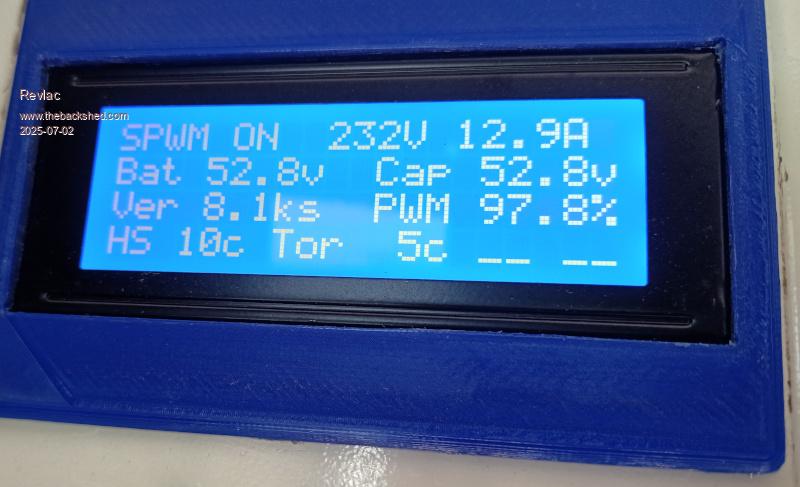 I'm testing a 90vDC bore pump in the top dam, run some heavy cable 80m to the dam and the DC pump ran well from the existing panels at the house, so will put a change over switch on one set of panels to run the pump......If I decide to go with this idea, details some other time. Cheers Aaron Off The Grid |
||||
| KeepIS Guru Joined: 13/10/2014 Location: AustraliaPosts: 2177 |
The high PWM for that load level Looks like toroid turns ratio or not enough turns on the secondary or incorrect number of turns for the primary. Admittedly my efficiency is little lower because of the low idle PWM value that I have (around 71%), but with a 6kw load mine is still in the low 80%. I did this because I need to start induction loads drawing well over 23kW for a few seconds on startup. My mains pressure water pump is barely noticeable on the Inverter "0 to 1200A" DC input Current meter _ Edited 2025-07-03 09:26 by KeepIS NANO:Inverter V 8.2ks - Linux AvrDude GUI script V4.1 |
||||
| analog8484 Senior Member Joined: 11/11/2021 Location: United StatesPosts: 203 |
Interesting, is there an equation for transformer turn ratio vs PWM drive level? For example, if I want 80% PWM drive at rated load then how does that translate to transformer turn ratio? |
||||
| KeepIS Guru Joined: 13/10/2014 Location: AustraliaPosts: 2177 |
There is a lot of information on the Forum on that topic, online calculators for winding a Toriod of X area to around 1 Tesla, and other info for selecting the desired turns ratio and required DC input voltage for a given worst case battery input voltage. Winding the secondary for a higher AC output voltage and adjusting the primary "battery input" winding will lower idle PWM, the disadvantage of lower PWM is likely higher FET switching current for a given AC load, I have had no issues though. NANO:Inverter V 8.2ks - Linux AvrDude GUI script V4.1 |
||||
| analog8484 Senior Member Joined: 11/11/2021 Location: United StatesPosts: 203 |
Yeah, I've read several of the threads on transformer winding but don't remember seeing any closed form equation for PWM drive to transformer turn ratio. Qualitatively the relationship is clear but iterative trial and error seems to be way most people have done to get specific PWM drive level. It just seems cumbersome when dealing a big transformer. Hmm ... is that because of a higher risk of saturation from fewer primary turns? Edited 2025-07-05 02:44 by analog8484 |
||||
| KeepIS Guru Joined: 13/10/2014 Location: AustraliaPosts: 2177 |
Depends on exactly what you were referring to, if PWM at 3kW AC is 90% and you change the Toroid to give 80% PWM, then FET switching current should be higher for the same AC power. IMHO builders did not specifically target PWM % in the early inverters when winding a Toroid. Toroid saturation was reduced by the correct selection of flux density for a chosen Toriod. The % of PWM should also have an effect on AC regulation, if you were at 99% PWM @ 2kW and your loads are in the 3kW to 5kW range I would imagine AC output voltage would sag, I could be wrong as these are overly simplified thoughts and opinions, as you know, there are complex systems at play here with many variables and interactions affecting inverter reliability, usable power, efficiency and final AC harmonic distortion levels. _ Edited 2025-07-05 15:47 by KeepIS NANO:Inverter V 8.2ks - Linux AvrDude GUI script V4.1 |
||||
| analog8484 Senior Member Joined: 11/11/2021 Location: United StatesPosts: 203 |
Yeah I see your point. No load vs under load conditions could yield different results. For no load condition, if you increased turn ratio by reducing primary turns (or increasing secondary turns) the current could actually be lower with a lower PWM duty cycle. There are definitely many variables. I can certainly imagine AC output sag under load with lower PWM duty cycles if the transformer winding impedances are not properly accounted for when increasing the transformer turn ratio. |
||||
| Revlac Guru Joined: 31/12/2016 Location: AustraliaPosts: 1277 |
Last night I heard something get knocked over on the floor outside, had a quick look around no Idea what it was, next morning discovered the fan cover and mesh had been pushed off the top of the inverter cabinet and was on the floor, I had an idea what it was as there was a few carpet snakes around 2 nights back. Thought I would open the door on the inverter cabinet and discovered a carpet snake at the bottom of the door against the batteries, it was a bit of a job getting it out as it didn't want leave, got it out eventually it was in good condition so put it outside, it moved close to the camera lens so its a little blurry photo, will have to seal up the cabinet a bit better I think. 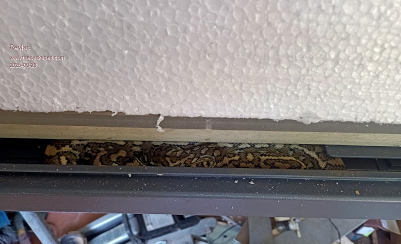 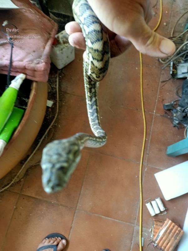 Cheers Aaron Off The Grid |
||||
Bryan1 Guru Joined: 22/02/2006 Location: AustraliaPosts: 2100 |
Lucky it was only a carpet snake mate the only snakes I have on this farm are eastern browns and black snakes. The huge black snake that lives out the back of the farm I did see last year make a hurried exit off my road as I was driving up and with the head gone from view the snakes body was more than the road width so yes it is a big one. My big problem is redbacks and lost count how many times i have been bitten. |
||||
| The Back Shed's forum code is written, and hosted, in Australia. | © JAQ Software 2026 |
