
|
|
Forum Index : Electronics : Bryan's Inverter build
| Author | Message | ||||
Bryan1 Guru Joined: 22/02/2006 Location: AustraliaPosts: 2101 |
More than likely this was self inflicted when I was setting up the buck converter and I have removed all the raised track and probed the board where no more shorts were found  I will solder some insulated wire to restore the connection but honestly was this track even needed as where it connects is at Vbat already ? |
||||
| phil99 Guru Joined: 11/02/2018 Location: AustraliaPosts: 3293 |
That may be the answer. During the capacitor charging phase all the initial charging current would have gone through that track, bypassing the resistors. Way more than it could handle. Unless the experts advise otherwise leave it out. Edited 2026-02-10 15:59 by phil99 |
||||
| Bryan1 Guru Joined: 22/02/2006 Location: AustraliaPosts: 2101 |
Yea I did make a positive and negative rails to terminate the wires easily and that connection was on the positive rail so I think you hit the nail on the head with that answer Phill. Anyway this is tomorrows job as it is a warm one and I will see how it goes running the inverter off the psu. I do still need to install the resistor bank and the 450amp switch once the inverter is tested and working. Regards Bryan |
||||
| Bryan1 Guru Joined: 22/02/2006 Location: AustraliaPosts: 2101 |
The more I'm thinking about this as I do have 2 more of the circuit boards for this inverter and in reality 2 more Aerosharp toroids to donate as that aliexpress inverter can make way for the project. Now today TinyT did provide some great suggestions for probing the IDC connector but it was a pain to setup those cheap male to female connectors I bought as most got loose with my 9" screen project that went south. So I do think a circuit board should be made to make the scope connections easier then as each inverter is made that 2K pot can be tuned so the inverter can go keep powering what I throw at it which will be my Unimig Viper 182 mig welder. Now as this is on 24 volts I do think it will be flatout on 4Kw and the only thing stopping me from going to 48 volts is that buck converter as the one I got has a 35 volt max voltage and I do need to find some that are 48 volt. Oh and another matched 48 volt batterybank. Anyway I am happy the problem was found so tomorrow does look promising. Regards Bryan |
||||
| Bryan1 Guru Joined: 22/02/2006 Location: AustraliaPosts: 2101 |
Ok so I beefed up that diode connection and set it all back up again where without the ribbon cable the caps charge in under a minute Now I turned it off connected the ribbon cable and got the same 400mA going thru the resistor bank and no DC voltage on the DMM so with the way the lcd is when that short happened is must of taken out the chips so I am going to order all new chips and while trying to use Arduino on MX25 it's back to it's old tricks where it won't program a nano so I'll have to get that AVRdude from jaycar. |
||||
| Bryan1 Guru Joined: 22/02/2006 Location: AustraliaPosts: 2101 |
Keepis was it the AVRdude you got from jaycar as I just did a search and no results was found. Edit: should of kept looking as the Jaycar one is the Duinotech one with a 10 pin header, also they have the 6 pin header which can be used on those 6 pins at the end of the board if I'm right. Edited 2026-02-13 08:21 by Bryan1 |
||||
| KeepIS Guru Joined: 13/10/2014 Location: AustraliaPosts: 2177 |
Avrdude is a command line programmer for programming micros, it is also installed as part of the Arduino IDE. Avrdude (Linux or Windows versions) can be downloaded and installed. NOTE: For windows there is a Graphical "GUI" program, AvrDudess, it makes it simple to set up and program the Nano with a hex file without using the Arduino IDE. This is not needed when using the Arduino IDE under Linux, as that appears to work correctly. NOTE: The Arduino IDE outputs various files including a HEX file, this is transparent to you when using the Arduino IDE. The device you need is the USBasp programmer board, you can set the USBasp board as the programmer interface in the Arduino IDE. USBasp Programmer Jaycar $14.95 As to the problem of the Arduino IDE not programming the Nano, this can happen if the Bootloader is missing from the Nano, of if the incorrect version of bootloader (old/new) is selected in the IDE, or the Nano is completely erased. The USBasp board does "NOT" need a bootloader in the Nano to program it, it program's the HEX file image directly into the Nano. Edited to include "NOT". . Edited 2026-02-13 10:20 by KeepIS NANO:Inverter V 8.2ks - Linux AvrDude GUI script V4.1 |
||||
| Bryan1 Guru Joined: 22/02/2006 Location: AustraliaPosts: 2101 |
Keepis this is the first time I've really heard about programming a nano with a hex file apart from your project. I do have to go out this morning so this afternoon I can try again, now I do want to get the code in the nano for the brain board so I can put my scope on and do those tests TinyT suggested then I can see first hand if the fet driver chips are still good. Now I will take out the power board too as I do think that short is on that board as I have probed the brainboard and couldn't find anything wrong with it. Regards Bryan |
||||
| KeepIS Guru Joined: 13/10/2014 Location: AustraliaPosts: 2177 |
Hi Bryan, Don't worry about the type of file, The Arduino IDE, when you compile the code, makes a number of files: If you use the USBASP in the IDE, it automatically selects the HEX file it made: If you program via the software programmer (default in the IDE) it selects the appropriate file to sends VIA the BOOTLOADER to the Nano. 1: Using: IDE itself: Nano needs a bootloader to load the code. 2: Using: IDE with USBasp - no bootloader needed in the Nano, it can be there but is not used. 3: The only thing that can program a bootloader back into the Nano, if it has been removed, is an external Hardware programmer like the USBasp board. Hope that makes sense. NANO:Inverter V 8.2ks - Linux AvrDude GUI script V4.1 |
||||
| KeepIS Guru Joined: 13/10/2014 Location: AustraliaPosts: 2177 |
I copied this from my post in the Micro forum: Checking and setting the USBasp device in Linux MX-25. Open a terminal, now plug in the USB programmer: Type in. sudo dmesg | tail -f | grep USB press enter, you should see something like the following: [4895.789204] usb 3-1.3: new low-speed USB device number 16 using xhci_hcd" [4895.904154] usb 3-1.3: New USB device found, idVendor=16c0, idProduct=05dc, bcdDevice= 1.02" [4895.904166] usb 3-1.3: New USB device strings: Mfr=1, Product=2, SerialNumber=0" [4895.904169] usb 3-1.3: Product: USBasp" Note the text: New USB device found, idVendor=16c0, idProduct=05dc, bcdDevice= 1.02 I can tell you now that MX-25 will see this USBasp device. You said you had added yourself to the dialout group. Now you add the USBasp device to the dialout group by: Right clicking on the desktop and selecting "Open root Thunar here" [WARNING] You now have full root access from the file manager, close Thunar as soon as you have carried out the following. Don't delete or rename anything. Select the File System Drive icon [left plane], then navigate to: /etc/udev/rules.d/ Does the file "99-USBasp.rules" exist in the rules.d directory? !!Be careful, there are other files with "similar" names. If not, make a new file called "99-USBasp.rules", or if the file exists then edit it, and, in either case, for Linux MX-25, add the following line: SUBSYSTEM=="usb", ENV{DEVTYPE}=="usb_device", ATTRS{idVendor}=="16c0", ATTRS{idProduct}=="05dc", MODE="0666", GROUP="dialout" Save the file and restart the system. . Edited 2026-02-14 11:19 by KeepIS NANO:Inverter V 8.2ks - Linux AvrDude GUI script V4.1 |
||||
| KeepIS Guru Joined: 13/10/2014 Location: AustraliaPosts: 2177 |
Posted in wrong location - deleted . Edited 2026-02-14 14:49 by KeepIS NANO:Inverter V 8.2ks - Linux AvrDude GUI script V4.1 |
||||
| Bryan1 Guru Joined: 22/02/2006 Location: AustraliaPosts: 2101 |
Well as I finally got the nano programmed I put it back on the board and made some jumper wires so I could check with my scope. Well on the first test no switching just low voltage static and tried the other tests and it does look like the IR2184 fet driver chips are toast. So got onto digikey and order half a dozen of them and to get upto free shipping got a decent set of side cutters Decided to probe the board again and found the electrolytic caps are goners too so I will replace all of them too. I unsoldered the 4.7uf cap which was right next to that Vbat rail and just got a dot showing when I tested the cap with my DMM. The 5.1 volt zener and other diodes all test true so looks like they survived. |
||||
| Bryan1 Guru Joined: 22/02/2006 Location: AustraliaPosts: 2101 |
Well decided to make a whole new brainboard with all new parts so firstly went thru my Altronics catalogue and placed the order online only to find they don't have 1uf and 4.7uf caps in stock so can't complete the order  So got onto Jaycar only find they can't work the shipping and won't let the cart be paid. Well that was a waste a morning so after lunch back onto digikey and so much for local companies as this country is a back water. Edit: well digikey had everything so now got all the parts on the way for making the new brainboard Edited 2026-02-16 12:30 by Bryan1 |
||||
| Bryan1 Guru Joined: 22/02/2006 Location: AustraliaPosts: 2101 |
Well the digikey order turned up yesterday so got the new board all soldered up apart from the 5V1 zener diode, silly me forgot to order some so looks like yet another trip down the hill to get one and won't be testing the inverter today but getting close once again. Regards Bryan |
||||
| Godoh Guru Joined: 26/09/2020 Location: AustraliaPosts: 667 |
HI Bryan, I have always found WES ( Wagner Electronics) to be very good at supplying what i need. I have ordered stuff in the past from other places but in the old days before covid when Australia Post worked, I would get orders the next day from WES. Good luck with the inverter Pete |
||||
| Bryan1 Guru Joined: 22/02/2006 Location: AustraliaPosts: 2101 |
Went down the hill this morning and got the zener diodes So with the LCD just showing 4 lines of crap as the nano didn't have the 6 pin header pins on desoldered the LCD board and put a header on the nano. AVRDude programmed in the hex generated from the sketch then found that single turn contrast pot was that touchy one couldn't set it so put on a 5K multi turn pot. Now I am powering the brainboard off the 15 volt input via my programmable power supply and noticed the LED wasn't on after mucking around for an hour got my phone out and yes the LED is on so it's a IRLED  put a different LED on and on turn it it does come on put a different LED on and on turn it it does come on I've programmed both nano's a few times now but the lcd won't show any data thru out the whole contrast range so at a loss. Still plugging along trying to sort this as I do want the LCD working before I put it all back together. Regards Bryan |
||||
| Bryan1 Guru Joined: 22/02/2006 Location: AustraliaPosts: 2101 |
So went and got that LCD I used on my failed MTTP projects and sure enough got ON HS 0 TOR 0 BV = 0.0V With that all sorted time to put it all back together and see if the inverter will work off my programmable power supply. I still need to setup that resistor bank and the 450 amp on/off switch which I'm going to use for the cap charge before turn on. |
||||
| Bryan1 Guru Joined: 22/02/2006 Location: AustraliaPosts: 2101 |
OK got it all setup with the ribbon cable connected and the DMM stayed on milli volts so turned it off straight away and took the ribbon cable off. 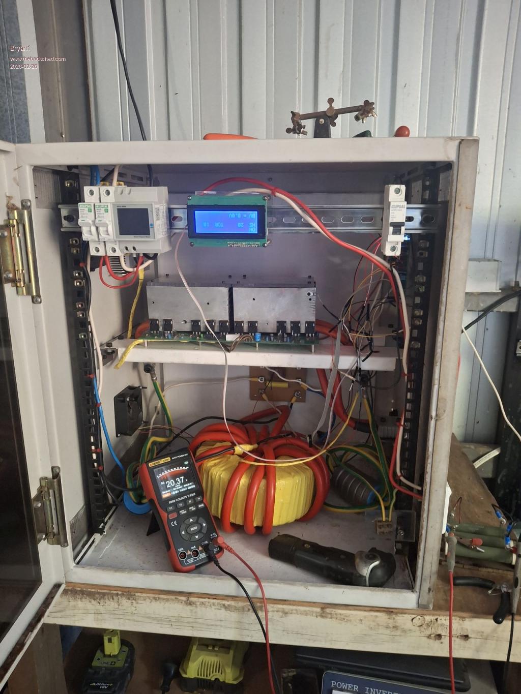 So yes the lcd is upside down  and tomorrow the power board is coming out to find where the problem is on that. and tomorrow the power board is coming out to find where the problem is on that.It good to see the LCD and brain board working so thats just the power board to sort out now. Regards Bryan Edited 2026-02-26 16:51 by Bryan1 |
||||
| Bryan1 Guru Joined: 22/02/2006 Location: AustraliaPosts: 2101 |
Ok another day to try and sort this out So the 240 volt AC side does show a dead short and as we can see in the photo above with the output from toroid the white wire go straight onto the AC board where the black wire goes thru the hole of that energy meter then onto the other side of the AC board. Which naturally would show a dead short as a single wire is used. Checking my first inverter build the AC board is the same yet when connected it does startup ? So looks like I need a hard lesson on the output side of this inverter as I am sure it is the problem Regards Bryan |
||||
| phil99 Guru Joined: 11/02/2018 Location: AustraliaPosts: 3293 |
The 240V winding of the TX will have a very low resistance. Is that what you are measuring? Disconnect the 240V winding then separately measure it and the rest of the 240V circuit. |
||||
| The Back Shed's forum code is written, and hosted, in Australia. | © JAQ Software 2026 |
