
|
|
Forum Index : Electronics : Bryan's Inverter build
| Author | Message | ||||
Bryan1 Guru Joined: 22/02/2006 Location: AustraliaPosts: 2101 |
Here is the test for pin TinyT suggested 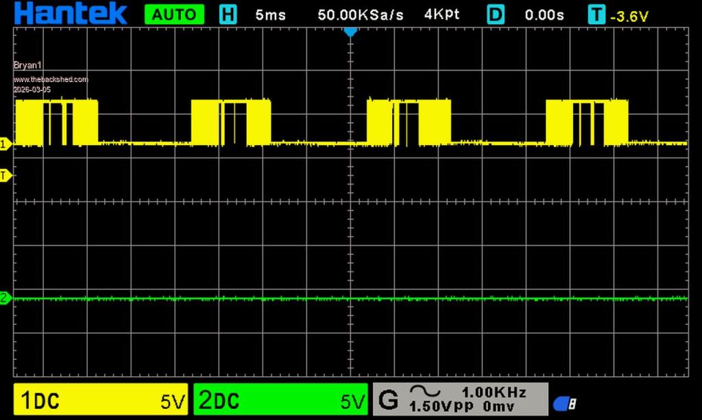 |
||||
| tinyt Guru Joined: 12/11/2017 Location: United StatesPosts: 559 |
Looks like probe grounds are not connected to the controller board ground. VS1 and VS2 wires should be connected to ribbon cable wires for pin 9 and 10. Edited 2026-03-05 11:41 by tinyt |
||||
| Bryan1 Guru Joined: 22/02/2006 Location: AustraliaPosts: 2101 |
Ok time for a reset as learning here  Ch1 L01 gnd VS1 + gnd Ch2 L02 gnd VS2 + gnd 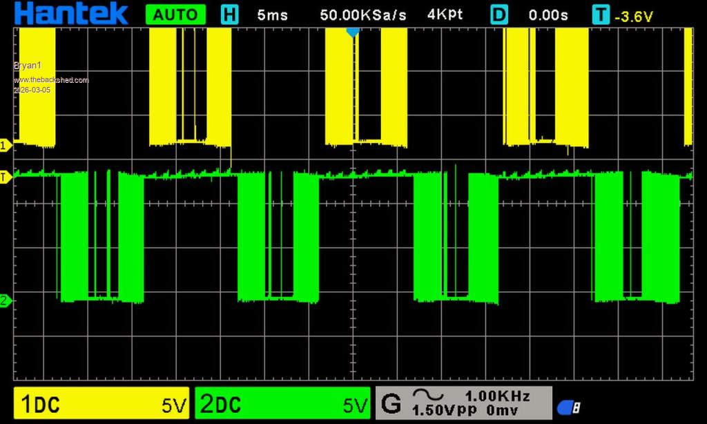 |
||||
| tinyt Guru Joined: 12/11/2017 Location: United StatesPosts: 559 |
Can you post close up picture of the area inside the red rectangle? Edit: Have to go, hope others can continue helping. 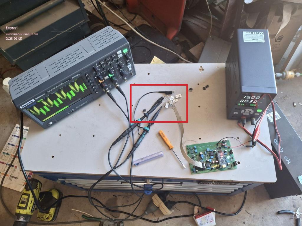 Edited 2026-03-05 12:01 by tinyt |
||||
| Bryan1 Guru Joined: 22/02/2006 Location: AustraliaPosts: 2101 |
Here is the test for CH 1 L01 Ch2 H01 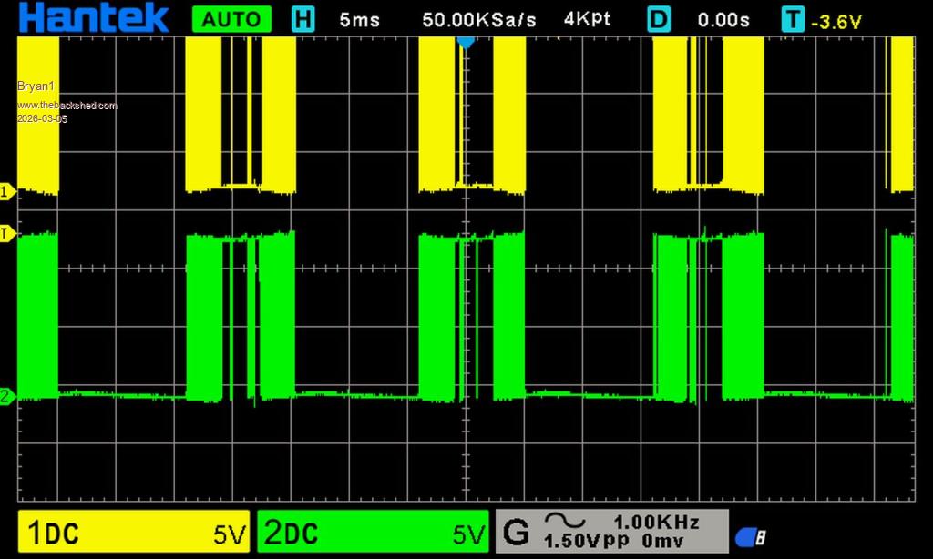 Now for that close up 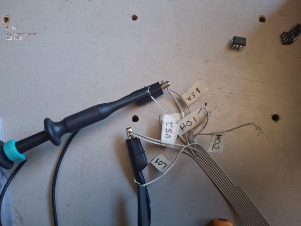 CH1 L01 CH2 H02 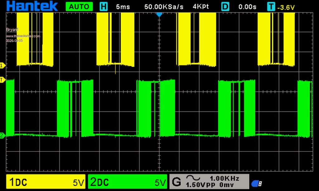 Edited 2026-03-05 12:06 by Bryan1 |
||||
| Bryan1 Guru Joined: 22/02/2006 Location: AustraliaPosts: 2101 |
I soldered up all wires on the ribbon cable to see if the signal improved and it didn't improve at all. Anyway as I had the test setup I tested all 6 of the 2184 chips and all proved to be OK Decided to have a look at the power board and with my probes leading on the Anderson connector seeing 517.9K ohms between positive and negative. So not sure if that is a problem Edited 2026-03-05 14:56 by Bryan1 |
||||
| tinyt Guru Joined: 12/11/2017 Location: United StatesPosts: 559 |
Ribbon cable wire identification looks good to me. Can you capture again: Ch1 L01 Ch2 L02 |
||||
| Bryan1 Guru Joined: 22/02/2006 Location: AustraliaPosts: 2101 |
Ch 1 L01 CH 2 L02 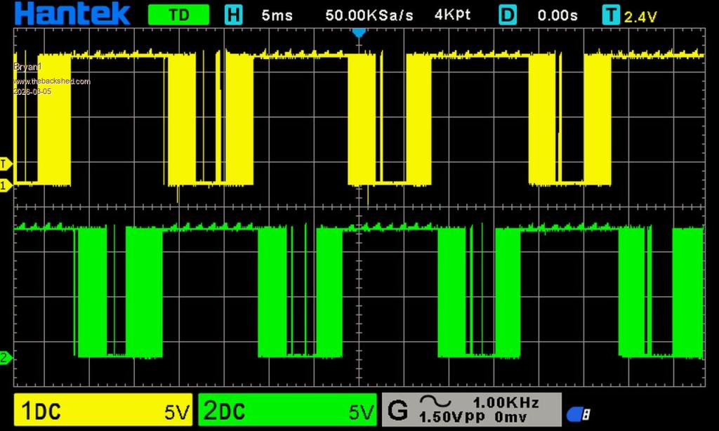 |
||||
| tinyt Guru Joined: 12/11/2017 Location: United StatesPosts: 559 |
If the intent of the nano code is to produce the waveforms and timing relationship is as shown in the sketch below, then the picoverter board is working correctly. 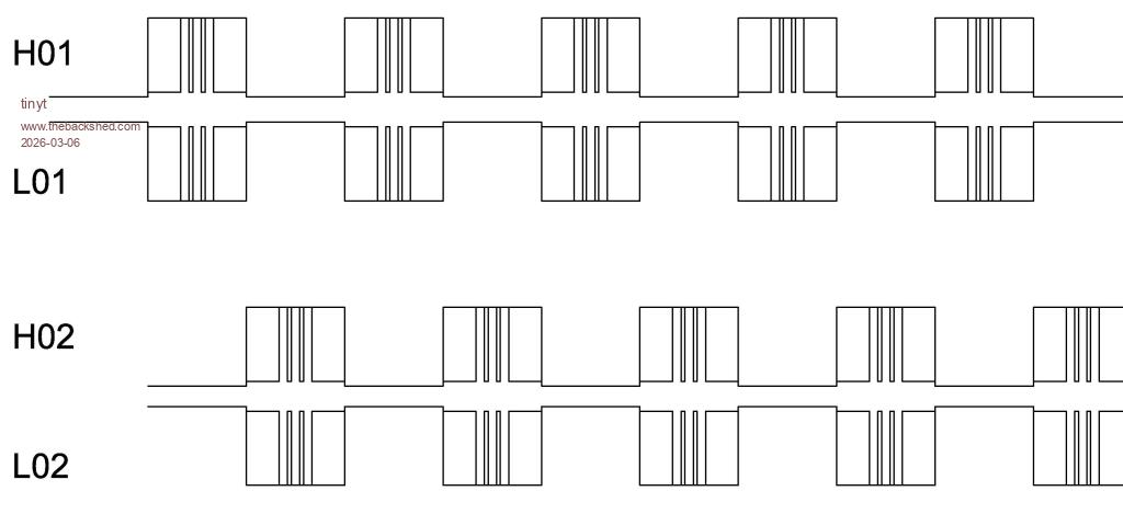 I guess it is time to examine the power board. |
||||
| Bryan1 Guru Joined: 22/02/2006 Location: AustraliaPosts: 2101 |
TinyT thanks for helping me on this After morning coffee's I will put the controller board back in place then take the toroid secondary output off the AC board then use my clamp leads connected to my DMM and see if it's the AC side pulling down the DC voltage. Like I've said before if the controller board is in the off condition then when voltage is applied via the resistor bank the caps do rise nice and quickly to Vbat, now when I turn on the control board the only thing that happens is the voltage instantly drops to 11.4 volts and the current goes from 50mA to around 250mA. Now to be safe I do set the max current to be 300mA for the resistor bank. |
||||
| mab1 Senior Member Joined: 10/02/2015 Location: United KingdomPosts: 282 |
I'm a bit confused by your reference to a resistor bank and setting the max current to 300mA: I get using a resistor bank to precharge the caps when running off a battery, but if you're testing with a bench psu set to 300mA, what is the resistor bank for? Do you not have the bench psu connected directly to the powerboard? If you're powering the powerboard via a resistor then the voltage will sag when it starts operating. Edited 2026-03-06 08:53 by mab1 |
||||
| KeepIS Guru Joined: 13/10/2014 Location: AustraliaPosts: 2177 |
When the capacitor bank values that you have on the power board are fully charged, then turning on the controller board, could/will, destroy components depending on the fault. It does not matter what series resistance or current limit setting you have on the power source, a charged high value of capacitance, especially anything over 1000uf, can kill most components and vaporise PCB tracks if there is a fault. Remember when the current drops from 50ma @ 22v to 250ma @ 11v, what you don't see is the discharge pulse current caused by the FETS discharging the CAPS down to 11.4v, one day the voltage will go down to near zero. Unfortunately that's the problem with solder in caps direct to the power board designs, it makes it difficult to safely test the power board. The only way to do this is to discharge the caps first, then connect the "Power board" to the "Controller". Now "slowly" raise the voltage to around 14v while monitoring the current. EDIT: And as Mab1 allured to, if you do this you do not need the precharge resistors in line. . Edited 2026-03-06 09:06 by KeepIS NANO:Inverter V 8.2ks - Linux AvrDude GUI script V4.1 |
||||
| Bryan1 Guru Joined: 22/02/2006 Location: AustraliaPosts: 2101 |
Mab I have 3off 40 watt 200 ohm resistors in parallel so around 60 ohm will limit the current when charging the caps. Now I use my programmable power supply where I can set the max voltage and current. To limit to pre charge current I used the back pads on the power board so the unit can be pre-started so yes the bench psu is connected to the power board. More info please... |
||||
| mab1 Senior Member Joined: 10/02/2015 Location: United KingdomPosts: 282 |
More info please... Ok.when the inverter is turned on, the powerboard will draw more current, so, if it connected to the psu via the resistor bank, the voltage on the powerboard will drop as you're losing volts across the resistor. I have the wiseguy boards with detachable capacitor boards so testing is not the same, but if you are testing with a current limiting bench psu you can connect the psu direct to the powerboard without the resistors and it will hold voltage in the powerboard until it's current limit setting is reached. Would be best though if you have a 2nd psu to do what Keepis is suggesting and power the control board off one supply with the powerboard at 0v, then slowly turn up the voltage on the powerboard as this avoids hitting the power components with charged caps |
||||
| Bryan1 Guru Joined: 22/02/2006 Location: AustraliaPosts: 2101 |
Well got the controller board back in and all connected 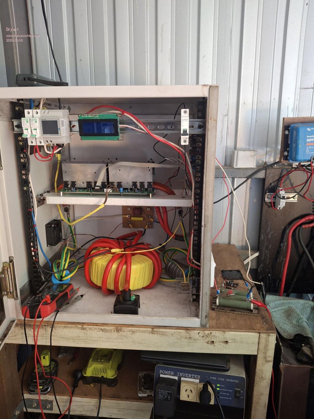 Now in the box is my 450 amp on/off switch I'm going to use, so on the inverter side of the switch can be powered by the resistors then when the caps are pre charged just turn the switch on and turn off the switch for the resistors. By the way that inverter below has been powering my shed since 2005 Edited 2026-03-06 09:39 by Bryan1 |
||||
| tinyt Guru Joined: 12/11/2017 Location: United StatesPosts: 559 |
I hope all power board components are good and soldered properly in their right location and orientation. Also make sure ribbon cable end connectors are plugged in their sockets in the right orientation. Edited 2026-03-06 09:49 by tinyt |
||||
| Bryan1 Guru Joined: 22/02/2006 Location: AustraliaPosts: 2101 |
Well it just as before and did have a bit of fun as on startup the nano was off even with the on/off switch on and had nothing on the lcd. Tried a couple of times and it was the same so used avrdude and a 5 metre usb cable and reprogrammed the nano. The nano kept playing up so soldered up a new nano to use. Now when I set the voltage to 15 volts the BV stops at 11.4 volts still even when the voltage is raised to 24 volts with the nano turned on, by turning the nano off the BV does rise to Vbat Now the current draw was staying below 100mA so not sure what is going on. Edited 2026-03-06 10:42 by Bryan1 |
||||
| Bryan1 Guru Joined: 22/02/2006 Location: AustraliaPosts: 2101 |
Ok so got the Vbat up to 25 volts with the control board in the off position then turned on the switch now the current did jump up to around 260mA and the voltage dropped straight away so I am wondering if I have sent 20 fets to heaven with my testing. |
||||
| mab1 Senior Member Joined: 10/02/2015 Location: United KingdomPosts: 282 |
I'm still not sure what's going on and not sure if my suggestioms are help or hinderance TBH, but if you ramp the voltage up with the nano running the powerboard voltage stops at 11.4v if i understand what you're doing. Am i right in thinking the transformer is connected? If so is it possible to try it without the transformer connected? When it's 'running' at 11.4v have you measured the voltages on the powerboard outputs (relative to 0v/ground)? Either with a voltmeter or the scope? |
||||
| Bryan1 Guru Joined: 22/02/2006 Location: AustraliaPosts: 2101 |
Mab I am trying to get the inverter to work off the psu to ensure everything is right as if I connect my 24 volt 735AH traction battery there could be some nice sparks if there is something wrong |
||||
| The Back Shed's forum code is written, and hosted, in Australia. | © JAQ Software 2026 |
