Notice. New forum software under development. It's going to miss a few functions and look a bit ugly for a while, but I'm working on it full time now as the old forum was too unstable. Couple days, all good. If you notice any issues, please contact me.
mozzie Guru Joined: 15/06/2020 Location: AustraliaPosts: 469
Posted: 05:31am 24 May 2026
Copy link to clipboard
Print this post
G'day Bryan, The "graphics" are just to indicate what the jog buttons are going to do, they are not buttons, it was just an idea and they should be another colour I guess.
Still playing with ideas for the Z-Axis drive, hopefully by the end of the week all the snippets in my head will have formed into a coherent plan Hopefully my "mate" will have returned my CNC control box so I can test it on that.
On the Pico here there has been no indication of white outs so might be a good idea to put it all onto PCB's and see what happens. The interference from the stepper drivers can be very hard to isolate. Like you are seeing, my mates CNC router was sensitive to anyone standing in a certain spot near the machine, must have been RF reflections but after trying every trick in the book we ended up putting a timber box there instead, problem solved an earthed steel cabinet may also have worked, not sure.
Only thing I would recommend on your PCB layout above is to widen the earth and VCC tracks, the backlight does drag a bit of juice. Looking good otherwise.
Regards, Lyle.
mozzie Guru Joined: 15/06/2020 Location: AustraliaPosts: 469
Posted: 05:52am 24 May 2026
Copy link to clipboard
Print this post
Hi Bryan, Some more thoughts on the surface grinder machine.
On the old machine here, the pneumatic cylinders were added to take up play in the Z-axis slides, they were worn in the centre and needed re-grinding, so the air cylinder loaded them against the good side of the slide and problem (almost) solved.
The problem you say is the backlash in the leadscrew on the Macson, we had a similar problem on the small grinder here and it was eventually solved.
So the problem was found to be the packing grease in the Z-axis slides had gone hard, the machine relies on the weight of the grinding head to keep pressure on the leadscrew to take out the backlash. Because the grease was causing sticsion, the head would stick until it was forced to move then drop by the backlash amount, VERY BAD.
In the end we took off the grinding head, brake cleaned the whole lot and reassembled, then spent a lot of time getting the gib strip in the Z-axis adjusted just right, too loose and you get movement, too tight and you get sticsion and the head ratchets down like you are seeing.
Might be worth looking into.
Regards, Lyle.
Bryan1 Guru Joined: 22/02/2006 Location: AustraliaPosts: 2297
Posted: 06:12am 24 May 2026
Copy link to clipboard
Print this post
Ok Lyle I widened the Vcc and GND tracks to 1.5mm and just sent it off to JLCPCB where the same $3.50 charge so for $7 got 5 off of the boards needed I also checked the shipping with the first board and yesterday it left HongKong so it won't be far away.
Now the beauty about my design the SDCard is taken care of so maybe it could be used for G_Code files once the stepper system is all worked out as repeat settings for the X axis will be constant. Now the Y axis as it is stepped 1/2 the width of the grinding wheel a new file for different width grinding wheels can have it's own files.
Eg: 3mm for a 6mm wide wheel, 4 mm for a 8mm wide on etc
The Z axis once the height say using a rollie paper under the stationary grinding can set the height the Z axis goes in step mode for putting on a cut.
Now lets say we do one step on the Z axis and find we need to increase it to 2 or more the Z setup screen can be used to input a new step value.
Honestly I do think with the spindle motor start it should be a manual external switch so the user in total control. Also a nice big external E_Stop would also be a good thing.
Now I just tested those push buttons and all of worked then got another white out so that part of the code is working nicely.
Regards Bryan
Bryan1 Guru Joined: 22/02/2006 Location: AustraliaPosts: 2297
Posted: 06:24am 24 May 2026
Copy link to clipboard
Print this post
As I writing when you posted again now with the Z axis I did give it a good greasing which did loosen it up and got the stepper working. Now I have put that thrust bearing under the coupling and preset the thrust bearing on the bottom of the leadscrew so yes backlash testing still has to be done which should be minimal.
Also I did clean off as much grease as I could which did cleanup the slide.
The ideal of a shock absorber is a good idea now also a coupling of good heavy-duty compression springs would do the same job one on each side of the Z axis slide. Now with that coil winder of yours can it wind heavy-duty springs.
mozzie Guru Joined: 15/06/2020 Location: AustraliaPosts: 469
Posted: 06:28am 24 May 2026
Copy link to clipboard
Print this post
Hi Bryan, Just an idea, if you power down the stepper drivers and run the code do the whiteouts stop? this will prove its power / interference.
Even then it could still be a bad connection in the breadboard
Regards, Lyle.
Bryan1 Guru Joined: 22/02/2006 Location: AustraliaPosts: 2297
Posted: 06:36am 24 May 2026
Copy link to clipboard
Print this post
What I found with the white outs When I did that limit test after I did 3 of them it went and only a USB reset would fix it, now with my 3.5" lcd the white outs never happened. A few times when it was fired up the white out was there too, now surprising the touch worked in the white out condition and the stepper code still had the steppers armed so I just turned the power supplu offline when it happens.
Bryan1 Guru Joined: 22/02/2006 Location: AustraliaPosts: 2297
Posted: 07:11am 24 May 2026
Copy link to clipboard
Print this post
Now surprisingly it's working so having a play with the Z axis and I got my dial indicator on and just trying to calibrate the distance.
Finally got the step count and somehow it doesn't sound right 6450 steps for 1mm of travel with a 8000 microstep setting.
Now going 1mm going up was repeatable over 5 goes then going down 1mm after the stepper had stopped moving the dial indicator did float 0.55m back to the zero setting on the dial.
So this does prove I need to install either the springs or a shock absorber to counter the wheel breaking fault.
Regards Bryan
Mixtel90 Guru Joined: 05/10/2019 Location: United KingdomPosts: 9237
Posted: 07:46am 24 May 2026
Copy link to clipboard
Print this post
As a matter of interest, is the stepper supply GND connected to the Pico supply GND or is everything fully opto-isolated?
You have to bear in mind that SMPS supplies can't safely have either of their output pins connected to mains earth as that bypasses a capacitor in the supply and allows switching noise to get out. Unfortunately it also means that one or both of the output pins has an AC voltage to mains earth, albeit limited to a low curent. I usually measure about 80-90VAC from the output of a USB charger to mains earth! Imagine the fun you can have with noise problems when one supply has the capacitor on the +ve pin and the other has it on the -ve pin.
At the same time, it's not a great idea to power the control logic from the same supply as the stepper motors, even if the voltage is something like. Big spikes love supply rails dearly and steppers love to produce big spikes. :) It *may* be possible to use suitable LC filtering, but that may need some experimentation to make sure that it doesn't make things worse under some conditions.
I think I'd like to power the control logic from a linear supply with -ve and all screening connected to mains earth and the steppers from a SMPS (to get the necessary current) then opto-isolate everything linking control to the steppers and use screened twisted pair wiring to limit switches. I'm a belt and braces person though. :)Mick
Bryan1 Guru Joined: 22/02/2006 Location: AustraliaPosts: 2297
Posted: 08:16am 24 May 2026
Copy link to clipboard
Print this post
Mixtel the power for the microstepper comes from My programmable power supply where the stanby current is around 600mA now when a stepper does energise the current goes to around 1.2 amps then drops back to the stanby current. Now the 5V logic is coming from the breadboard Vcc line and the pico 2 is powered from the USB now the ground connection from the power supply isn't conected to the breadboard ground.
mozzie Guru Joined: 15/06/2020 Location: AustraliaPosts: 469
Posted: 08:28am 24 May 2026
Copy link to clipboard
Print this post
G'day, Mick, when it comes to steppers or VFD I agree you can never have enough sheilding / grounding / ESD protection, they seem to manage to inject RF noise into everything. Opto-isolation is often the only cure. Not so sure on the SMPS, having repaired a few the A-N-E cap(s) are on the input side and the output side is isolated by the transformer and feedback opto-isolator, some are earthed, some are floating and a couple have a link to select either option. This is more regarding industrial supplies, plugpack supplies are another kettle of fish, as are cheap s**t of unknown origin.
Bryan, sounds more like the whiteout might be a bad connection on the breadboard somewhere
Can I suggest you try backing off the Z-Axis gib strip a bit and spraying a heap of WD40 / CRC into the slides and leadscrew, interested to see if it makes a difference. Also having the vibration from the motor running can change how it moves.
6450 steps at 8000 microsteps is very close to 1.25/1.27, is 6450 what you have the Z-Axis steps/mm set to?
Regards, Lyle.
phil99 Guru Joined: 11/02/2018 Location: AustraliaPosts: 3416
Posted: 08:29am 24 May 2026
Copy link to clipboard
Print this post
The DM556 stepper drivers being used have opto-isolated inputs so my guess is radiated interference.
As it is still on a breadboard perhaps extra capacitors on the 5V and 3V3 supplies close to the Pico are worth a try.
Bryan1 Guru Joined: 22/02/2006 Location: AustraliaPosts: 2297
Posted: 08:35am 24 May 2026
Copy link to clipboard
Print this post
Those white outs did come at odd times a few times when the USB is connected the LCD shows the serial stream then when I used the run command it did it, now also a few times after using the touch screen a couple of times it did it also.
Now when I finally got the Z axis calibrated and found that 0.55mm backlash drift it worked for a good 10 minutes so I will put some cap's on the breadboard tomorrow and use the 4 0ff AAA batteries to power the LCD as that could be an issue.
Now when I was using the ILI9488 I didn't have a white out once and when I got the 4" LCD it was a straight swap out so all the wiring was still in place.
lizby Guru Joined: 17/05/2016 Location: United StatesPosts: 3885
matherp Guru Joined: 11/12/2012 Location: United KingdomPosts: 12054
Posted: 02:11pm 24 May 2026
Copy link to clipboard
Print this post
Wrong thread - sorry Edited 2026-05-25 00:11 by matherp
Mixtel90 Guru Joined: 05/10/2019 Location: United KingdomPosts: 9237
Posted: 03:36pm 24 May 2026
Copy link to clipboard
Print this post
SMPS almoost always have a class Y cap between one side of the transformer primary and and one of the output terminals. This has nothing to do with mains supply filtering, it is to reduce EMI from the supply. Class Y (hopefully!) so that it will fail open circuit without killing anyone. :) Earthing one side of the output makes this cap useless so the EMI is increased.Mick
These are a 4" ST7796 LCD with either XPT2046 RES or FT6336 CAP touch. Quite a nice display but sadly not IPS. I ordered a couple for testing and they make a nice upgrade from the 3.5" without using any more pins, also don't have the headaches of the 9488 MISO problems.
Mick, I think that's why the link is optional, gets the supply past EMI testing but allows us to fit it if needed.
Time for bed Regards, Lyle. (its 04:20 here)
lizby Guru Joined: 17/05/2016 Location: United StatesPosts: 3885
Bryan1 Guru Joined: 22/02/2006 Location: AustraliaPosts: 2297
Posted: 11:52pm 24 May 2026
Copy link to clipboard
Print this post
Well while walking up my shed this morning thought about those heavy springs I had in my shed
So I do think they may be strong enough to take the slop out of the Z axis so I will fit them and give it a try.
Also shown is the project box I will be mounting the LCD screen on and the PCB's can also go in there and I'll make a mount so it's easy to see on the surface grinder.
Regards Bryan
mozzie Guru Joined: 15/06/2020 Location: AustraliaPosts: 469
Posted: 04:49am 25 May 2026
Copy link to clipboard
Print this post
G'day Bryan, Those springs look like they will be up to the job My little sis had a trampoline but in the end all the springs went missing, me and the old man had better uses for them
Some further thoughts, if you say you are getting 1mm travel with 6450 steps at 8000 steps / REV that means 1.24mm pitch leadscrew, that doesn't sound right A simple test would be to draw a line on the coupling (or use the grub screw as a reference) and see if it does 0.8 turns, otherwise something is up s**t creek.
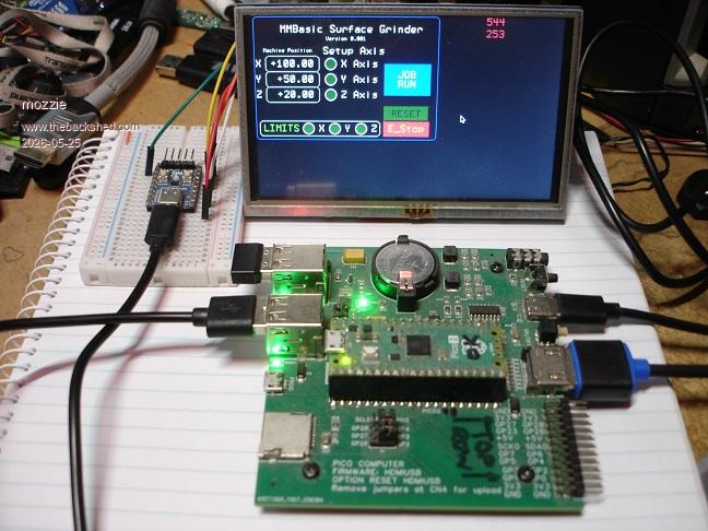
With Peters addition of the GUI system to the HDMI build we might be close to being able to use much larger HDMI / touch monitors for a screen, more testing to follow. This is just a mockup test but it does work
Regards, Lyle
Bryan1 Guru Joined: 22/02/2006 Location: AustraliaPosts: 2297
Posted: 05:18am 25 May 2026
Copy link to clipboard
Print this post
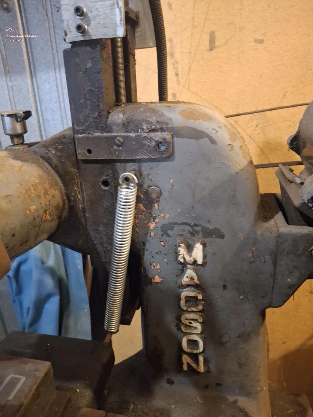
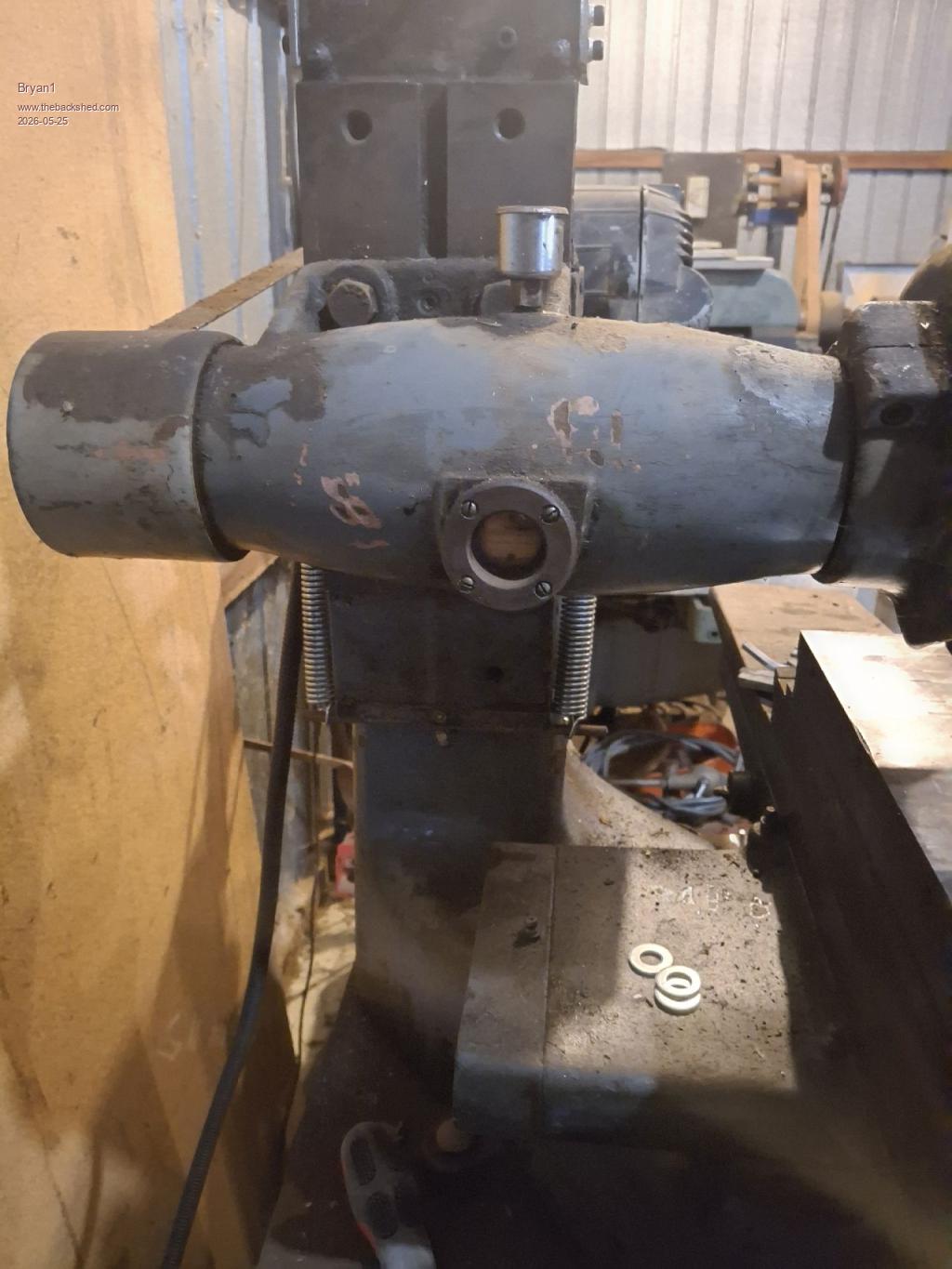
Very nice Lyle Just did a test with these springs and I reckon the drift is now under 0.1mm on average, now it could be put in the code when the Z axis goes down it goes straight backup to putting pressure on the thread. I did measure 1.6mm backlash using 1mm of travel and my metric dial indicator which does let me see the drift happening.
Now for the top of the springs there is a 1/4"BSW thread so I put longer set screws in to accommodate the springs. Now on the rear there was a hole at the same height so the springs are balanced.
For securing the other side of the spring I just used some 1/4" round bar and it sits nicely under the bottom plate.
Now just tested on the up travel and the coupling does go about 0.8 of a turn and it's the same on the down travel after the backlash is taken up.
Page 16 of 22
Print this page
The Back Shed's forum code is written, and hosted, in Australia.

 Notice. New forum software under development. It's going to miss a few functions and look a bit ugly for a while, but I'm working on it full time now as the old forum was too unstable. Couple days, all good. If you notice any issues, please contact me.


 Print this post
 Hopefully my "mate" will have returned my CNC control box so I can test it on that.
 an earthed steel cabinet may also have worked, not sure.


 Regards, Lyle. (its 04:20 here)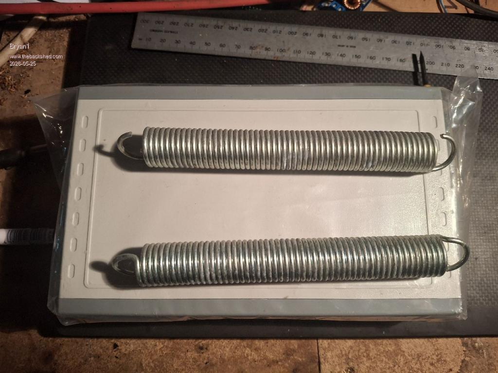
 My little sis had a trampoline but in the end all the springs went missing, me and the old man had better uses for them