
|
|
Forum Index : Electronics : Bryan's Inverter build
| Author | Message | ||||
| mab1 Senior Member Joined: 10/02/2015 Location: United KingdomPosts: 282 |
I figured that much -  - but is the big output transformer connected to the powerboard for these tests? (That's what it looks like in the last picture) - but is the big output transformer connected to the powerboard for these tests? (That's what it looks like in the last picture)I was wondering if you could scope the powerboard outputs without the transformer / inductors connected, whilst it's trying to run with 11.4v on the powerboard. |
||||
Revlac Guru Joined: 31/12/2016 Location: AustraliaPosts: 1277 |
Agree with above. Bryan, The fun sparks might be ok for someone else to watch, not so good for your own gear, unless its like fun sparks I had early this week...was recoverable.  Anyway a few observations If all the fets were shorted there would be a much lower voltage than 11.4v at the powerboard. The Toroid you had posted earlier used about 12w idle (if that's correct), it alone will use a bit more than that running, so total power could be upto around 500ma from the supply. I can be corrected on any of this, just about to do some dish washing. Cheers Aaron Off The Grid |
||||
Bryan1 Guru Joined: 22/02/2006 Location: AustraliaPosts: 2101 |
Ok taking Mab's suggestion undid the VS1 and VS 2 connections and set Ch1 to VS1 and Ch2 to VS2 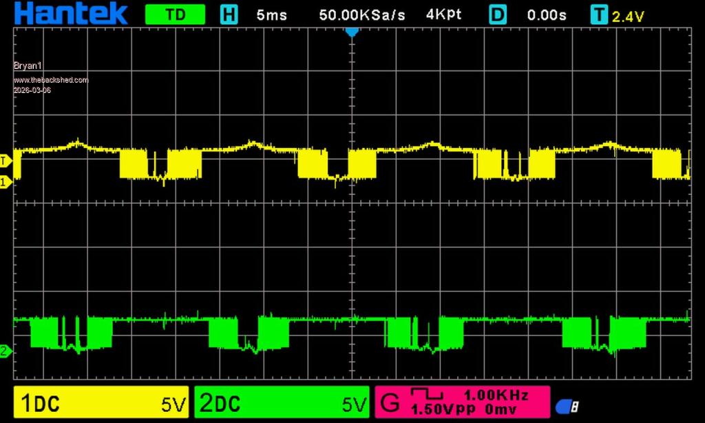 Now with the psu set at 24 volts and the DMM connected to the resistor bank does go to VBat so when the switch is turned on the current goes upto 240mA from 70mA then drops off as the voltage drops to 11 volts. Edited 2026-03-06 12:30 by Bryan1 |
||||
| phil99 Guru Joined: 11/02/2018 Location: AustraliaPosts: 3293 |
|
||||
| Bryan1 Guru Joined: 22/02/2006 Location: AustraliaPosts: 2101 |
CH1 is connected to the outside leg on TIP42 CH2 is connected to the outside leg on the TIP41  DC voltage 10 volts on the DMM connected to the resistor bank Yes Phill VS1 and VS2 are out of circuit so the toroid is offline Any scope connection tips are welcome Edited 2026-03-06 12:41 by Bryan1 |
||||
| Bryan1 Guru Joined: 22/02/2006 Location: AustraliaPosts: 2101 |
Ok I took the resistor out of circuit and limited the psu to 300mA, with the board off the pre charge was well under 300mA  Now when I turned it on with a 28 volt DC input the DC voltage dropped to 16 volts and with the probes connected to the tip chips the wave form didn't move with the dropping voltage. Also the LCD is affected with screen going faint like it was lacking power. OK just used the scope to check all the fets on the front where all of them showed the same wave form, now the ones at the back are too hard to get to. Also I noticed when I raised the current to 500mA the board did take it so turned it off. Edited 2026-03-06 13:12 by Bryan1 |
||||
| tinyt Guru Joined: 12/11/2017 Location: United StatesPosts: 559 |
Bryan, Is there a schematic of the power board I can look at? |
||||
| Bryan1 Guru Joined: 22/02/2006 Location: AustraliaPosts: 2101 |
Had to for a search so here it is 2021-04-19_210951_Schematic_powerboard_2021-04-19.zip Edited 2026-03-06 14:02 by Bryan1 |
||||
| KeepIS Guru Joined: 13/10/2014 Location: AustraliaPosts: 2177 |
I just want to clarify (I had a rough night again with little sleep) so bear with me: 1: Power supply was set to 28V @ 300ma. 2: The power board and the Controller were connected together, but NOT to 28V. 3: The the CAP bank on the power board was fully discharges (ZERO voltage). 4: Then you switched the 28V DC on to the Inverter. With controller and power board ready to immediately start powering up, the nano will be sending SPWM to the power board as the Supply voltage increases slowly, limited to 300ma when the caps are charging. The Nano will need around 11V to 14V before it can start. The LCD screens will flicker and the displays may look corrupted, especially when they are powered up very slowly, like when the Cap bank is charging. NANO:Inverter V 8.2ks - Linux AvrDude GUI script V4.1 |
||||
| Bryan1 Guru Joined: 22/02/2006 Location: AustraliaPosts: 2101 |
I just want to clarify (I had a rough night again with little sleep) so bear with me: 24 volts @300mA to start then just raised the voltage on the psu a volt at a time Yes the power board and control board are connected on DC connectors, the control board via the 15 volt DC-DC buck converter Yes when the DMM was showing zero volts Yes Edited 2026-03-06 14:52 by Bryan1 |
||||
| KeepIS Guru Joined: 13/10/2014 Location: AustraliaPosts: 2177 |
 NANO:Inverter V 8.2ks - Linux AvrDude GUI script V4.1 |
||||
| Bryan1 Guru Joined: 22/02/2006 Location: AustraliaPosts: 2101 |
Just soldered up a lug to fit that reject 50sqmm VS short cable and in the morning I'll setup the resistor bank and switch on my DC power board. I will be disconnecting the Anderson Connector for the battery so that a morning job. So once that is done lets see if the inverter does start off the battery or I won't need endorsement in "The Blown Fet Club" with 20 going at once  |
||||
| Bryan1 Guru Joined: 22/02/2006 Location: AustraliaPosts: 2101 |
Just thinking as those 6 caps I put in are 10,000uf 63 volt it would take a bit of time like more than a few minutes to fully charge to VBat and with my tests today should of waited longer. |
||||
| phil99 Guru Joined: 11/02/2018 Location: AustraliaPosts: 3293 |
1 time constant, T (secods) = R (Ω) * C (F) > ? 200/3 * 10000*6 / 1000000 4 seconds > Full charge = 5 * time constant = 20 seconds. |
||||
| Bryan1 Guru Joined: 22/02/2006 Location: AustraliaPosts: 2101 |
Well as all my tests this afternoon was with VS1 and VS2 off connected them up and yes Phil this time the DMM went to 28 volts pretty quick so turned on the nano 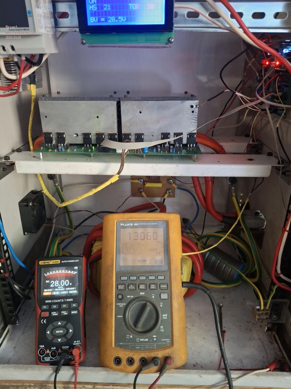 Now the DMM on the left is the DC voltage and my old fluke meter is showing the AC side so a nice clean sinewave but 13 volts  but eh it's better than the 3 volts before but eh it's better than the 3 volts before I do have to state the resistor bank was left out of circuit for this test and the current draw was well under 100mA while getting upto voltage. Now I did set the current to over an amp on the psu and the current draw was 520mA so not far away now Edited 2026-03-06 16:57 by Bryan1 |
||||
| Bryan1 Guru Joined: 22/02/2006 Location: AustraliaPosts: 2101 |
Now for the next test I took the output from the toroid to clamp probes and put them on my fluke in scope mode so as we can see the good sign wave has gone. 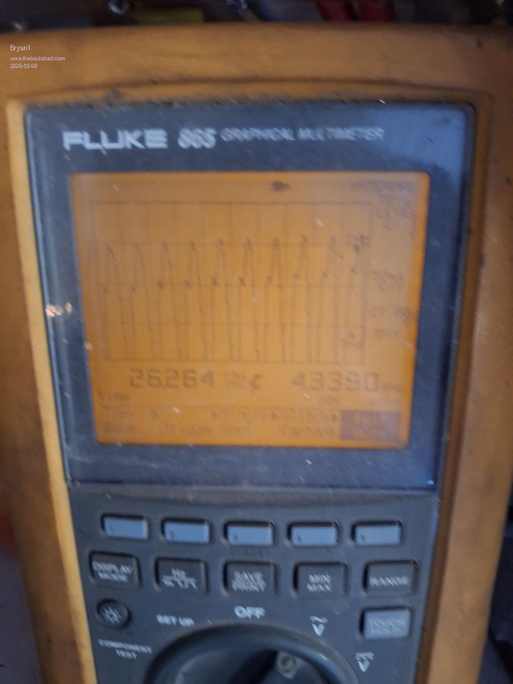 Having a couple of cool ones is getting my courage up The PSU is on 28 volts and the current draw is the same around 500mA now I have set the max current to 1.1 amp and it hasn't gone close to that. Now with my next test I will hook up the scope. Edit: hooking up my scope to AC is more than I've done on this scope so some guidance would be nice. Edited 2026-03-06 17:30 by Bryan1 |
||||
| Bryan1 Guru Joined: 22/02/2006 Location: AustraliaPosts: 2101 |
Now here is another thought one output from the toroid goes straight to the AC board where the other output goes thru that energy meter then back to the AC board. So could the unequal resistance in the AC between cables be causing the low AC output. Edited 2026-03-06 18:08 by Bryan1 |
||||
| KeepIS Guru Joined: 13/10/2014 Location: AustraliaPosts: 2177 |
Don't think so, it sounds more like the AC output voltage is set low on the nano AC feedback line, or something is causing the cal input to the Nano ADC to be wrong. Without any load, the AC should be a smooth sinewave. I normally use a small isolation transformer when driving the DSO, usually I am measuring a few channels and DSO earth is best kept floating from the AC output, IE even a simple 240v to 6v to 15v small transformer will do, the DSO connects to low voltage side and is now fully isolated. NOTE to forum: That is a very "simplified response", way to do it and reason for doing so!! EDIT: Bryan, your SMALL scope sine wave could be distorted by coupling from the switching side of the Inverter board and wiring. It should only show a bit of 25khz fuzz. . Edited 2026-03-06 19:12 by KeepIS NANO:Inverter V 8.2ks - Linux AvrDude GUI script V4.1 |
||||
| Bryan1 Guru Joined: 22/02/2006 Location: AustraliaPosts: 2101 |
KeepIS I do have to say the inrush current quote is off as my psu did show a 75mA current draw so with all my precautions aside when I do the fix to my battery DC board the inverter will work or go bang. Now what gets me as everything thing is hooked up the inverter to work with 1.2amps of current where it's only showing 16 AC so I am thinking eh why not take one choke out and see the difference. Now when I searched for that schematic for TinyT it was on Poida's homebrew inverter thread back in 2021 as I did know it was on this forum. I did read today to turn the 2K pot to zero volts and as I only learned that today it is a job in the morning. Regards Bryan |
||||
| tinyt Guru Joined: 12/11/2017 Location: United StatesPosts: 559 |
On the pico board: Check DC voltage between the two red arrows in the picture below. 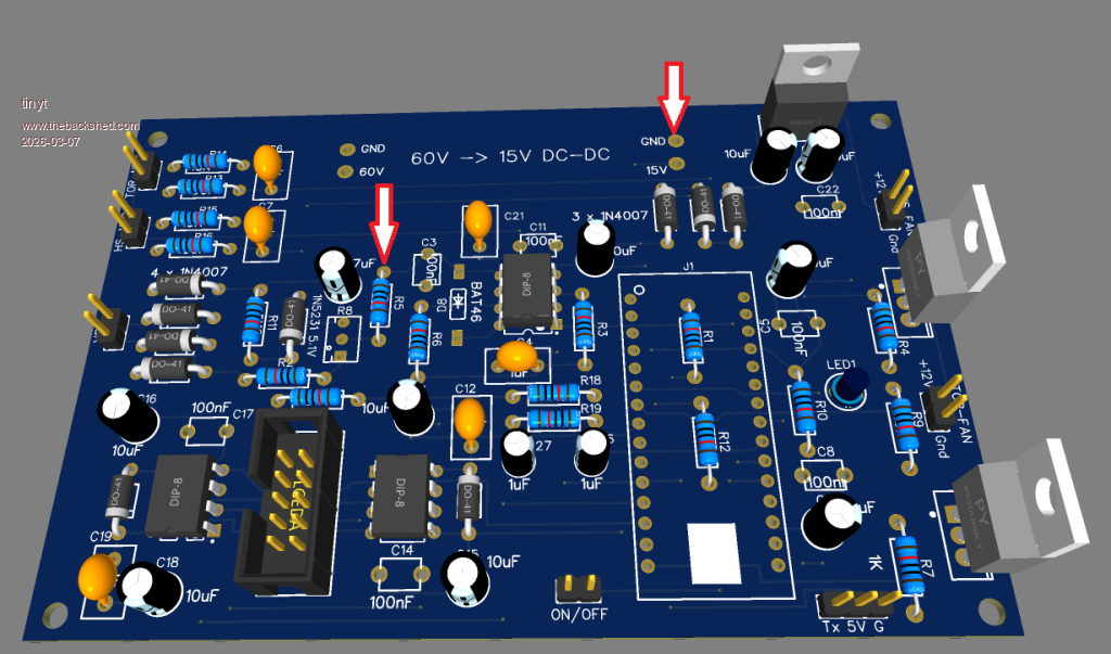 It should be much lower than 5vdc. If not, check D8(BAT46). It could be shorted or orientation is reversed. Edited 2026-03-07 00:42 by tinyt |
||||
| The Back Shed's forum code is written, and hosted, in Australia. | © JAQ Software 2026 |
