Notice. New forum software under development. It's going to miss a few functions and look a bit ugly for a while, but I'm working on it full time now as the old forum was too unstable. Couple days, all good. If you notice any issues, please contact me.
mozzie Guru Joined: 15/06/2020 Location: AustraliaPosts: 469
Posted: 05:39am 25 May 2026
Copy link to clipboard
Print this post
Hi Bryan, That leadscrew does look pretty fine pitch, 1.24mm pitch is very close to 20.5TPI so have you tried it over 10 or 20mm in case its a bit gummed up? I'd reckon 20TPI would sound about right. Maybe stick a thread gauge on it
I still reckon it looks all a bit dry, can I suggest once again to go at it with WD40 / CRC and see if it helps, the little machine here worked wonders afterwards.
That MACSON is certainly a BEAST
Regards, Lyle.
Bryan1 Guru Joined: 22/02/2006 Location: AustraliaPosts: 2297
Posted: 06:00am 25 May 2026
Copy link to clipboard
Print this post
Well just stuck a thread gauge on and you hit the nail on the head 20TPI yea I still need to do a full clean up of the machine.
This Macson is designed for a 6" or 150mm diameter wheel and just on looking at mine I have a 4mm 6mm 8mm and 12mm width wheels.
Now not trying to tell you how to suck eggs but to test a grinding wheel for defects just tap the wheel as you go around and it should give a nice ring, now if it does a dull ring throw the wheel in the bin
A bit of history in this surface grinder, back in the 90's when my Dad came over to visit me in SA I found him the surface grinder and it went back to NSW. Now when my Dad died all his gear was over in Busseleton WA so this grinder has gone coast to coast then back home again in my shed. Edited 2026-05-25 16:05 by Bryan1
Bryan1 Guru Joined: 22/02/2006 Location: AustraliaPosts: 2297
Posted: 08:03am 25 May 2026
Copy link to clipboard
Print this post
Honestly Lyle with all 3 of my steppers working via the touch screen I do think we can finally move a notch on the version as the code does work for me most of the time.
Now a few times the GUI buttons aren't drawn fully mainly the jog+ one now that maybe just the breadboard setup.
So what do you reckon about the version uplift as I do think it should.
Now with that bar for the lower spring mount I'm just going to weld the bar to some flat bar and there are 2 set screws I can tap into to bolt that lower plate on.
Now with my testing the centreline of the spindle in 110mm above the magnetic table so that extra 30 odd mm of spring pressure should remove that 0.1mm drift.
I did find another 2 150mm grinding wheels and all of them got the ring test and came true and honestly it did pay to check seeing how far they traveled on road freight.
Regards Bryan
Mixtel90 Guru Joined: 05/10/2019 Location: United KingdomPosts: 9236
Posted: 08:33am 25 May 2026
Copy link to clipboard
Print this post
I'm loving this project. :)
Big, heavy, risky as hell machine, a 1 USD non-industrial microcontroller and a healthy dose of Chinese electronics. What could possibly go wrong? ;)
Just don't fit a wheel while you are still using a breadboard and air-supported wiring, please! It might not be one of the greatest ideas.
I've always liked computers where you could *see* them doing something physical.Mick
Bryan1 Guru Joined: 22/02/2006 Location: AustraliaPosts: 2297
Posted: 08:41am 25 May 2026
Copy link to clipboard
Print this post
Don't worry mate it will be awhile before a wheel goes on and my boards will be here very soon so when the electronics are all sealed in that project box it should be much better with no errors like those white outs where are a pain.
So Slowly getting there and no rush as this project will be done properly and we may find Lyle get his going first.
Regards Bryan
PhenixRising Guru Joined: 07/11/2023 Location: United KingdomPosts: 2100
Posted: 11:45am 25 May 2026
Copy link to clipboard
Print this post
Watching with interest. 1982 was the last time I had a noise issue. It was before we switched to differential drivers/receivers on incremental encoders.
I am surrounded by EMR from huge PWM servo-drives and have temporary wiring and exposed boards all over the place. Never have an issue. Just be sure to have snubber diodes on relay and solenoid coils.
vegipete Guru Joined: 29/01/2013 Location: CanadaPosts: 1185
Posted: 09:33pm 25 May 2026
Copy link to clipboard
Print this post
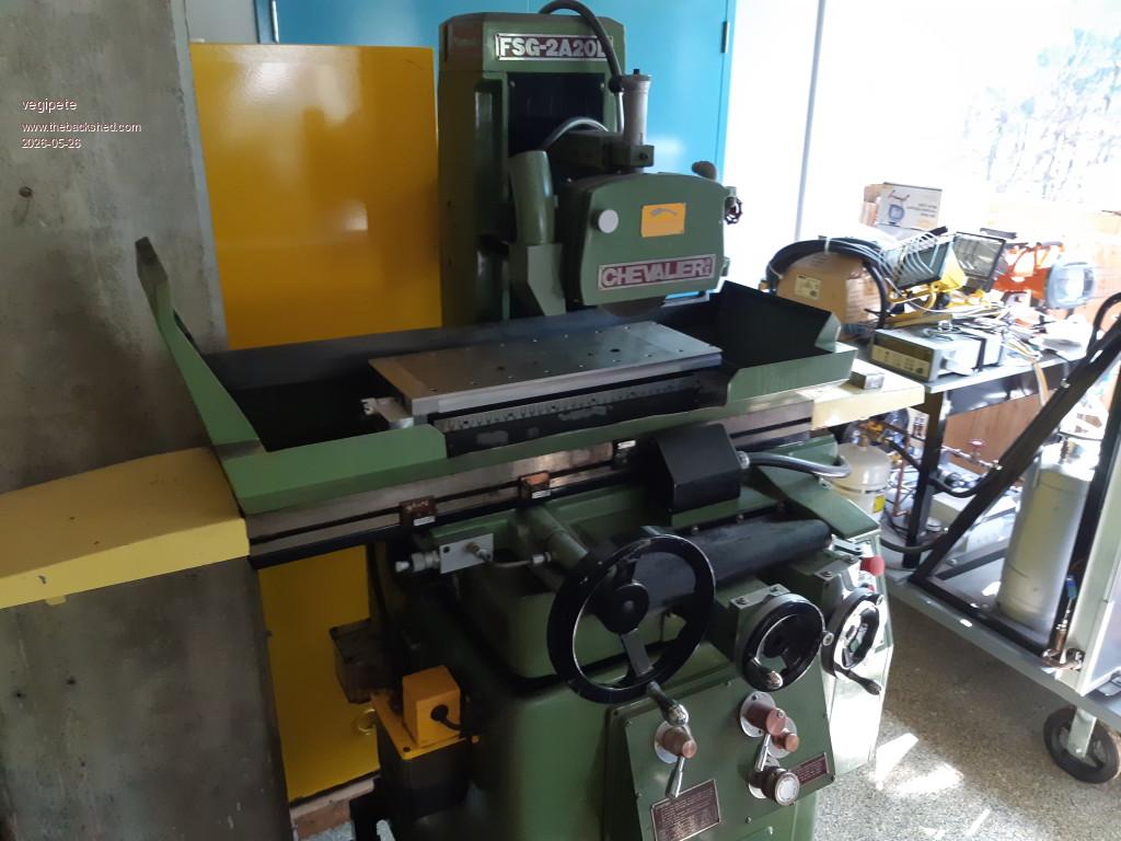
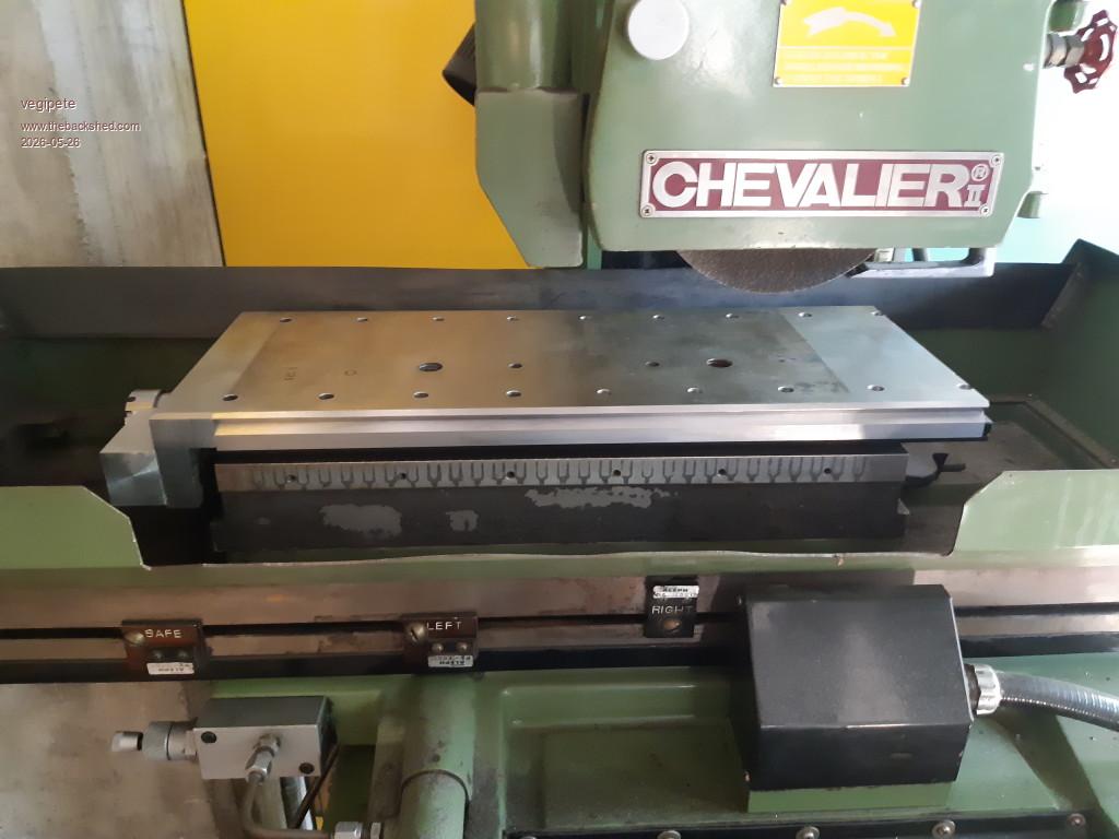
I plonked the work piece onto the grinder - the mag chuck will need moving slightly to get the travel to work. This piece is the cross slide for a lathe that I've been building for a rather long time. Mainly I want to clean up the top surface cosmetically. 21" inches end to end.
Perhaps I'm being overly critical of the state of the automatic hydraulic system. It kinda works, but it leaks on the floor, so we don't bother to use it. The machine gets so little use that no one has troubled to tear it apart and replace bad seals.
Bryan1 Guru Joined: 22/02/2006 Location: AustraliaPosts: 2297
Posted: 10:54pm 25 May 2026
Copy link to clipboard
Print this post
While mulling over the morning caffine intake thinking about today's tasks that need doing
With the X axis I need to take it apart and make up the adjustment for the tensioning sprocket so the 1/4" chain can run nice and smooth. Also need to make a guard to fit as chain sprockets do bite and bite hard.......
Then once that's all done put on the dial indicator and work out the backlash from the driving gear on the rack and note it down for later code use.
The Y axis just needs calibrating and also the backlash worked out also 2 small guards to close in the bracket to keep prying fingers out.
Now with the Z axis yesterday I measured 1.65mm backlash with the spindle 110mm above the magnetic table which produced 0.1mm drift. So by going down 5mm each time it will be interesting to see if the drift does come down and see if the backlash stays the same.
Checked out the details of my PCB's and the main board is now in Vic and should be here by the weekend with luck. The LCD board is two thirds done and should ship in the next day or so.
Regards Bryan
PhenixRising Guru Joined: 07/11/2023 Location: United KingdomPosts: 2100
Posted: 11:57pm 25 May 2026
Copy link to clipboard
Print this post
With respect...Industry myth which is my ongoing soapbox issue.
I had a huge war with this same mentality at General Motors. All kinds of "experts".
I said OK you guys love your Allen Bradley stuff so much, why am I even here?
They soon backed down. They got a generic Taiwan PC motherboard and issued repeat orders. Funnily enough I just received two rack mount units, here in the UK from North Carolina. 1990 issue. They are totally fine but they are rebuilding the mechanical parts and wanted me to check them over.
Per my ongoing rant, this "industrial rugged" is pure horse doo-doo. You really belive that paying a fortune for say a display and waiting on the "two week" backorder is a GOOD thing? No it ain't but these brainwashed morons would prefer that a production line stays dead for two weeks. Imagine if it was a dead heating system or a blocked toilet at home....would they be OK for two weeks?
Apologies for the rant but this is the real world. When it's only company cost, let's virtue signal.
mozzie Guru Joined: 15/06/2020 Location: AustraliaPosts: 469
Posted: 01:30am 26 May 2026
Copy link to clipboard
Print this post
G'day Bryan I agree we should bump the code to 0.002 now the setup routine for the machine is sorted
On some further crunching of the grey cells, what do you think about this?
As you noted, we are running out of I/O on a single Pico, and whilst it looks like making it all work is possible, is going to require some dirty tricks in the program. We also have noise being picked up in the wiring from the Pico to the stepper drivers and LCD.
My proposed solution is to use a PICO2 running the stepper system on your PCB down with the stepper drivers to look after the stepper motor outputs and limit switches / estop etc. A second PicoMite linked via RS422 (2xRS485) will look after the display and touchscreen, linked by a screened 6 core cable.
Advantages:
Wiring to stepper drivers shortened. Wiring to LCD / HDMI / TOUCH shortened and away from noisy drivers. Will work on your existing PCB. Enough I/O for all 6 limits and motor outputs. RS485 link is noise tolerant and cheap (could also use opto isolators instead). Easy to move display around machine, only 1 cable. Ability to run any display without changing stepper driver board. Ability to fit LED indicators from spare I/O on display board. Move RTC to display board to increase I/O on stepper board. 2 Pico's are cheaper than an RP2350B board. (I think)
DIS-advantages:
2 sets of code to sort out and update. Ummmmm.......
I think this is the way to go and will be trying out some ideas to see how it works. What do you think?
Phenix, don't want to get off topic here but I couldn't agree more, sadly the OH&S moron normally doesn't have an understanding of how the machine operates or is operated, leading to some rediculous requests in the name of safety, to the point of making machines un-usable.
If you think industrial / factory automation is bad, try mobile plant: The E-Stop must stop the truck engine! : hmmm, ok, so what about when it shuts down the truck engine at 100km/h going downhill? : No, it must shut down the engine : Have you ever driven a truck : Ummm No : Yeah thought so.... Also the idea that cutting the ignition signal on a diesel engine will stop it is laughable
The risk assessment system is far better but trying to cover all the bases on some plant is an exercise in frustration.
The only good point with the better PLC's is monitored outputs, they will halt the PLC if it detects an output that is not in the driven state, otherwise it is mostly 5 x the price for nothing special.
Thankfully on the surface grinder front, it is my machine, in my shed, and will be fitted with an apropriate STOP system. In reality I find the surface grinder far less intimidating than anything for cutting wood, the table saw is far more dangerous in my view
That is all I'm going to say on the subject in this thread.
VegiPete, that is one nice looking machine. Shame about the hydraulics, maybe time to look into some seals for the cylinder, or fix it like a british car and fit a drip tray, works on my Mini's and Landrovers (I love em but they do mark their territory)
Ok, offended enough of the world, time to do some work.
Regards, Lyle.
Bryan1 Guru Joined: 22/02/2006 Location: AustraliaPosts: 2297
Posted: 04:07am 26 May 2026
Copy link to clipboard
Print this post
Well for what seemed an easy job turned out having a late lunch, now I was going to cut some firewood as it is that time of year so went and made some fresh 2 stroke oil then got my chainsaws out to give them a run first as it has been awhile since they were used.
My 14" 172 started up nicely and warmed up so it was easy starting then it was time for my 25 year old farm boss with a 20" blade. No way it would run when the trigger was pressed so fired up my air compressor and gave the chainsaw a good clean, then got my small adjustment screwdriver and re-tuned the old girl.
Then went to start my tractor only to find that old epoxy job I did on the isolation switch finally gave way so no power for starting
Had a think about it and as the bolts securing the isolation switch did come thru several threads soon found the bolt was 6mm and I could make a bracket to hold it in so it made contact.
Well the time old what to use came back then saw the spacer plate out of the aerosharps would fit the tee so duly cut a 15mm strip and drilled the first hole. After I got the first 2 bends done I did find the part made bracket was holding firm once I did up the nut. Went to start the tractor and it fired up
So off cutting firewood I went got just over 1/2 a trailer done and that last seasoned branch soon dulled the blades so called it a day and got enough firewood to keep the wife happy.
Ok Lyle hold ya horses mate my pcb's haven't even rocked up yet so lets not put the cart before the horse.
Now I do intend to mount the DM556's in the cupboard so they are out of sight and won't collect dust etc over time. Mounting the DM556's on the side of the cupboard is just for testing.
Now I do have one of Peter's big DIL boards with 2350B on and thats what I using before we decided on using the 2350A. Also I bought that 4" LCD for this project and it will sit nice in that project box which is going to sit about 200mm away with the current setup so lets just keep it with 1 pico2 A and LCD now as this is for my project once the code is setup that single pico2 PCB will be enough to run any 3 axis setup where one just needs to setup the stepper drivers and connect them to the axis breakout pins.
Anyway time to start finally making that guard where the aerosharp scrap will fit the bill of of materials.
Regards Bryan
Bryan1 Guru Joined: 22/02/2006 Location: AustraliaPosts: 2297
Posted: 07:09am 26 May 2026
Copy link to clipboard
Print this post
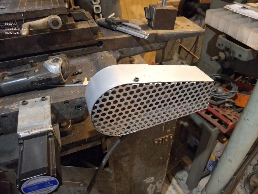
Finally got the X axis guard made and the back plate just needs a tweak so the guard sits nice and even away from the chain.
Still need to make the mounting brackets but now one step further on this project
Now I do have a heap of 2-3 metre lengths of twisted pair wiring and thats what I use for my breadboard setup, now I've never used it before for it's intended purpose so I would guess the white wire on each twisted pair would go to earth wouldn't it ?
Regards Bryan
Mixtel90 Guru Joined: 05/10/2019 Location: United KingdomPosts: 9236
Posted: 09:35am 26 May 2026
Copy link to clipboard
Print this post
If you are connecting to normal microswitch-type limit switches then colours don't matter for twisted pair, set your own standard. :) The point of it is that any interference picked up on one wire is also picked up on the other. At the pico end the interference is equal on both wires but, as one wire is grounded, in opposite phase so it cancels out to some degree.
Screened twisted pair would have the screen connected to ground at the Pico end only.Mick
mozzie Guru Joined: 15/06/2020 Location: AustraliaPosts: 469
Posted: 12:36am 27 May 2026
Copy link to clipboard
Print this post
G'day Bryan, Fair enough mate, be interesting to see how it goes once its on the PCB's, that gaurd is looking good
It looks like your setup will all work on a Pico2 as long as you are happy with 3 inputs for the limit switches, if you use the circuit shown earlier the LED across the limit shows which one is tripped anyway.
The small machine here will be better suited to the 2 PicoMite solution but the main software will be similar enough that it won't matter much. As a bonus it will also work with your driver PCB design.
As for the STOP system, keeping the drivers enabled for an extra couple of seconds after the STOP button is pressed will allow the Z-Axis to raise and apply braking to the X and Y axis to bring them to a halt. WIN WIN
Regards, Lyle.
Bryan1 Guru Joined: 22/02/2006 Location: AustraliaPosts: 2297
Posted: 04:07am 27 May 2026
Copy link to clipboard
Print this post
Well got a couple of emails one from Aussie Post saying my package will be here either Friday or Monday also got an email from JLCPCB saying my second order has now shipped so that won't be far away.
Lyle when I can get to the grinder today I will move and rewire the push buttons so I can test the limit LED's and ensure they all work correctly. Now I do need to cycle the X axis so I can get to the chain joint link but that guard does need the final fit then the X axis is all ready apart from the limits.
Now speaking of the X axis limits on the front of most grinders is a slot so the mechanical limits could be adjusted to suit the travel. Now somewhere in my shed is those slotted LED sensors so one on each side could set the X axis on travel stops.
As the X axis just goes back and forward it could go past one of the sensors on each side of the machine then set for an interrupt then the DIR can be reversed, the backlash component added and off it goes again to the other side.
So for the 2nd stage testing the X axis can go back and forward so the LED sensors can be all setup then that's it the X axis is sorted.
Well I have one thing to do which is switch my mobile over to Belong Mobile then the only Telsux thing I will have is my email address which doesn't cost. Also I have now become a dole blugger and setting myself up for retirement where I found my first payment never went thru, it turned out when I applied the software deleted a number off my bank account details and my first payment was returned. It did take well over an hour and while I was waiting got a free hearing test My right ear is normal but my left ear was a tad dodgy so it does look like I have to get rid of that wax ball then my left ear will be back upto scratch
It is good to see my hearing is still sound so when I ask someone to repeat something it could just be my selective hearing
Ok time for some fun on this grinder now got everything out of the way nearly....
Regards Bryan
Bryan1 Guru Joined: 22/02/2006 Location: AustraliaPosts: 2297
Posted: 05:28am 27 May 2026
Copy link to clipboard
Print this post
Ok rewired the push buttons and can confirm the LED's on the LCD does conform to this
Stepper initialized - 100KHz timer active Warning: Soft limits not configured. Use STEPPER LIMITS to set working area. Hardware limit switches configured Stepper armed - executing buffered commands Hardware limit switch trip - emergency stop Asserted: Z_MIN, Z_MAX Mode forced to TEST, buffer cleared, position unknown Clear the switch condition and re-home (G28), then STEPPER RUN Stepper armed - executing buffered commands Hardware limit switch trip - emergency stop Asserted: Y_MIN, Y_MAX Mode forced to TEST, buffer cleared, position unknown Clear the switch condition and re-home (G28), then STEPPER RUN Stepper armed - executing buffered commands Hardware limit switch trip - emergency stop Asserted: X_MIN, X_MAX Mode forced to TEST, buffer cleared, position unknown Clear the switch condition and re-home (G28), then STEPPER RUN Stepper armed - executing buffered commands Hardware E-STOP trip - emergency stop Clear E-STOP switch, re-home (G28), then STEPPER RUN
Each time a button was touched the holding current turned off straight away and on touching the RESET button does turn the holding current back on.
Now just tried to go into the X axis setup and found the page corrupted then got a white out.
So a bit of frustration on further testing, now reading some threads and your project Lyle it finally clicked here where the RC12 update solves a question I've been thinking about for years how to connect a mouse so an old VGA screen can be used and even HDMI screens.
So it does look like once we get this surface grinder done I reckon the next project is converting my CNC to work in MMBasic where a nice big HDMI screen is used.
Then as each step is done it can be drawn on the screen so the shape of the product is shown as it's being made.
That can be a job using my HDMIUSB board I have here as there is enough in/outs to implement the stepper system. Then all we have to is open a file and read it line by line to do the CNC code.
Anyway back to my current project.
Regards Bryan
phil99 Guru Joined: 11/02/2018 Location: AustraliaPosts: 3416
Posted: 05:58am 27 May 2026
Copy link to clipboard
Print this post
If this is also the case for an E-stop perhaps a return spring on the Z-axis might lift the wheel clear.
Last place I worked had return springs to close all motorized valves on the reticulated high temp hot water system. If there was a E-stop or power fail magnetic clutches disengaged the motors. 150°C at 1000kPa can be a tad nasty.
Bryan1 Guru Joined: 22/02/2006 Location: AustraliaPosts: 2297
Posted: 07:54am 27 May 2026
Copy link to clipboard
Print this post
Phill I do have a dual spring setup and I will get the right tension on them so when in operation there will be no drift.
Now on the subject of the E_Stop on this surface grinder, as the X axis travel will be from F150-F500 it will be a second or a few where the grinding wheel is working so plenty of time each stroke to apply the E_Stop in the free air cycles.
The Y axis is going travel the required mm for the grinding wheel when the X axis finish's the left cycle then cycle thru until it's time to return so some code could be
while DIR = 1 : IF DIR = 0 add backlash
So the backlash on the screw reversal is taken care of and this can be applied to every axis so the machine position is kept.
While I'm waiting for the PCB's to arrive tomorrow I'm bringing up that 24" HDMI screen and start playing with the GUI code so my CNC project can get underway where a few years ago I did try with my CMM2 and referring back to that thread does have plenty of info including the PIO code Harm gave me which did get a DM556 working.
Like this surface grinder project does use the same DM556's so the code is mostly done to get a good starting point. Having a nice big screen working with a mouse or like with the update of bluetooth an app to control the buttons on the screen that can of worms has just been opened up where the world is my oyster
Honestly everything I have asked for Peter has included in MMBasic and with Lyle coming onboard just reading his code has taught me a heap
Now with testing today I did find moving the X axis the code did hang after I changed the travel number box. After doing a reset I found the same where trying to change the feed kept resulting in 0 showing and the code hung.
This could of been the breadboard setup and the poor connections it does now when I get this stepper board setup I can see if those errors persist.
The latest pico manual I have is dated 11th Feb 2026 so is this the latest one as this GUI code for HDMI has me biting at the bit where I can make the screen up and get a mouse to work with it.
With the G-Code every G cycle has it's own function so when I can get each G function done it can go in the library then the next one will be there for the challenge.
In Mach3 one just opens a file then it's run line by line so in MMBasic just opening a file and reading each command sorted by a , then a CLRF after the line is finished shouldn't be that hard to do.
Now I have a 3D printhead here I bought many years ago and now we have a 4 axis setup in the stepper code maybe I should do a 4 axis 3D printer project where full build details can be open source which can include a easy way to make your own filler cord from scrap plastic.
I do wonder if I took the oil out of the plastic first would it be the same plastic as all plastic is made from oil and I have made a still out of copper to make my moonshine I have thought of making one out of steel to do it.
Anyway those boards should be here soon so this first project can get finished.
Regards Bryan
Bryan1 Guru Joined: 22/02/2006 Location: AustraliaPosts: 2297
Posted: 07:47am 28 May 2026
Copy link to clipboard
Print this post
I have been thinking today about the issue of when the program starts the last known position is lost on a power down so what if we setup a button "Save Position" was made then the X, Y and Z axis positions can be saved in the Library for the next startup and the last known position can be set on startup.
Then the pico2 stepper code will always know the axis position but would this require the Steeper Position command to be a string so it can be updated at startup.
Regards Bryan
matherp Guru Joined: 11/12/2012 Location: United KingdomPosts: 12052
Posted: 08:10am 28 May 2026
Copy link to clipboard
Print this post
VAR SAVE/VAR RESTORE
Page 17 of 22
Print this page
The Back Shed's forum code is written, and hosted, in Australia.

 Notice. New forum software under development. It's going to miss a few functions and look a bit ugly for a while, but I'm working on it full time now as the old forum was too unstable. Couple days, all good. If you notice any issues, please contact me.


 Print this post