
|
|
Forum Index : Electronics : Bryan's Inverter build
| Author | Message | ||||
| KeepIS Guru Joined: 13/10/2014 Location: AustraliaPosts: 2177 |
The Inverter should easily produce 240vac with no AC load at under 1A @ 26vdc, that's 26 watts at idle, it should actually be below that in any case. Removing a choke will increase idle current AND, to put it in simple terms, take away some of the "last line of defence" protection for the FETS. NANO:Inverter V 8.2ks - Linux AvrDude GUI script V4.1 |
||||
| mab1 Senior Member Joined: 10/02/2015 Location: United KingdomPosts: 282 |
Fell asleep before i saw this. Then had to go to work. If that scope trace is vs1 and vs2, there is an asymmetry between them: the little peaks on the tops of the top trace. My guess (it is just a guess though - it's hard to understand what's going on), would be the gate drive is not getting though on one quarter - or the fets are not turning on. The outputs from the control board seemed ok in the earlier scope traces, so i'm wondrring if the +ve supply (Vtp om the schematic) for the high side drives is getting through ( i'm thinking they use bootstrapping to get the high side drive voltage, so in my mind there's more bits to go wrong there). My guess based on those scope traces is that vs1 high side is trying to turn on but vs2 high side isn't. But my guess is sort of based on the assumption the higher than expected current draw isn't caused by a short. Edited 2026-03-07 10:48 by mab1 |
||||
| tinyt Guru Joined: 12/11/2017 Location: United StatesPosts: 559 |
You are right about the asymmetry. Maybe Bryan can check orientation(pointing opposite to each other) and voltages at D25 and D26 on the power board. Voltage should be around 18vdc for the diode lead pointed to by the horizontal arrow. 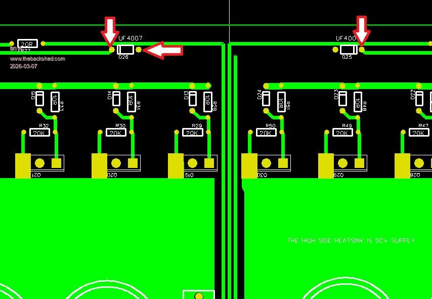 Edited 2026-03-07 12:01 by tinyt |
||||
Bryan1 Guru Joined: 22/02/2006 Location: AustraliaPosts: 2101 |
Ok got all the jobbies done so got some time to play  Setup the scope on VS1 and VS2 and Gnd Now the AC output was 14 volts on the fluke DMM PSU set to 28 volts and 1.2amp where the current draw was 500mA so about 14 watts. 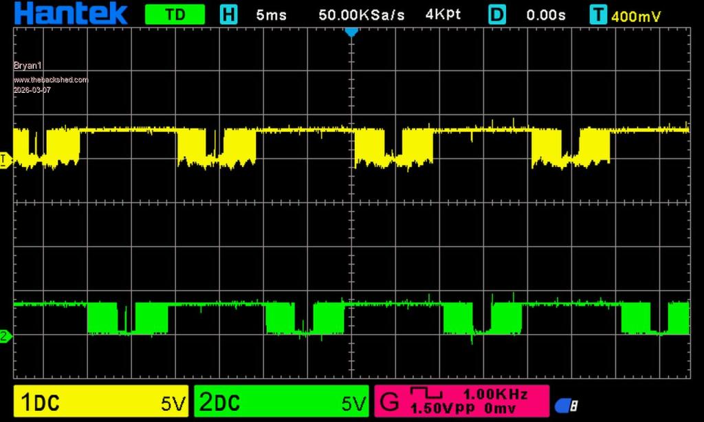 Now measuring that resistor after I turned the pot down quite a few turns was 568mV and I did notice on turning the pot out the AC voltage didn't change at all. TinyT I just had a look at those fast diodes and they are in the correct position. Edited 2026-03-07 12:27 by Bryan1 |
||||
| tinyt Guru Joined: 12/11/2017 Location: United StatesPosts: 559 |
VS1 and VS2 connected to the toroid transformer thru the inductors? Where is this measured? What is the Vtp voltage reading? |
||||
| Bryan1 Guru Joined: 22/02/2006 Location: AustraliaPosts: 2101 |
TinyT thanks for the suggestion of checking that bat46 as my fluke meter in diode mode showed an open circuit and question mark So replaced the diode and stay tuned as about to test.Edit: 24volts DC input 524mA current draw and 14 volts AC output where the probes are in the 240 volt socket Edited 2026-03-07 13:44 by Bryan1 |
||||
| tinyt Guru Joined: 12/11/2017 Location: United StatesPosts: 559 |
If it is open, it will not change anything. Actually you can operate the picoverter without it. It is just for over voltage protection of the nano input pin. But if it is reversed or shorted, it will force the voltage being read by the nano code to be very high, and make it 'think' that the AC voltage is too high. And I guess the code will adjust the pwm to lower the AC output voltage. Edited 2026-03-07 13:48 by tinyt |
||||
| tinyt Guru Joined: 12/11/2017 Location: United StatesPosts: 559 |
The voltage at the lead of the diode pointed to by the horizontal arrow?  |
||||
| tinyt Guru Joined: 12/11/2017 Location: United StatesPosts: 559 |
Please identify the numbered leads/terminals in the picture below. Edit: And what are the yellow(capacitor?) and brown(step down transformer?) parts. 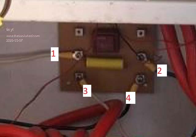 Edited 2026-03-07 14:13 by tinyt |
||||
| Bryan1 Guru Joined: 22/02/2006 Location: AustraliaPosts: 2101 |
As they are located on back of the board I can't get in to measure them |
||||
| Bryan1 Guru Joined: 22/02/2006 Location: AustraliaPosts: 2101 |
1. is a AC outlet from the toroid secondary which goes to the 16amp circuit breaker 2.The other AC outlet going to the other 16amp circuit breaker 3. output from toroid seconday 4. the other toroid secondary output that goes thru the hole of the energy meter and is the longer wire. The yellow part is a 5uf capacitor and the brown part is the 12AC transformer now I did do a test where I put the leads on the 12AC pins and it only showed about 300mV now when I turned it off the voltage did drop to zero. Edited 2026-03-07 14:19 by Bryan1 |
||||
| tinyt Guru Joined: 12/11/2017 Location: United StatesPosts: 559 |
Can you measure at the pin of the TIP31 pointed to by the arrow? 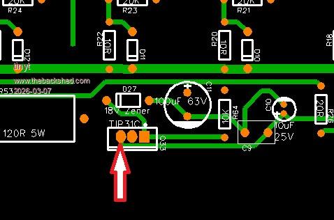 |
||||
| tinyt Guru Joined: 12/11/2017 Location: United StatesPosts: 559 |
Can you temporarily disconnect wires 1 and 2? Then measure AC output at terminals 3 and 4? |
||||
| Bryan1 Guru Joined: 22/02/2006 Location: AustraliaPosts: 2101 |
3.44 volts measured on the left pin, 6V on the centre pin and with the 18V zener 4.07 volts 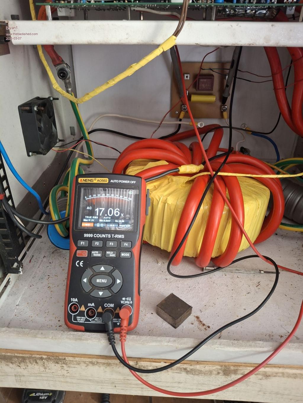 Edited 2026-03-07 14:41 by Bryan1 |
||||
| tinyt Guru Joined: 12/11/2017 Location: United StatesPosts: 559 |
That is too low, maybe your zener diode is not 18 volts. Measure the other two pins of the TIP31. And put back wires 1 and 2. Edit: If the zener diode is rated at 18 volts and your battery voltage is 24v-28v, R64(10K) should be much lower in value. Do you know the part number of the zener diode? If not try changing R64 to a value between 1k to 2k for a start. Edited 2026-03-07 14:50 by tinyt |
||||
| Bryan1 Guru Joined: 22/02/2006 Location: AustraliaPosts: 2101 |
OK took out the ribbon cable and tested the zener diode was 17.7 volts so the zener diode is correct mate. the left pin was 17 volts centre pin 24 volts and the right pin 17.7 volts So it does look like the power board is good. Edited 2026-03-07 14:55 by Bryan1 |
||||
| tinyt Guru Joined: 12/11/2017 Location: United StatesPosts: 559 |
If your battery voltage is 24v-28v, that 120 ohms 5 watts resistor should be lower in value, maybe close to 60 ohms. Edit: But if your final battery voltage is 48-56 volts, then you have to restore it to 120 ohms. Edited 2026-03-07 14:57 by tinyt |
||||
| Bryan1 Guru Joined: 22/02/2006 Location: AustraliaPosts: 2101 |
TinyT the resistor bank is out of circuit and on turn the current charging the caps is only 50mA |
||||
| tinyt Guru Joined: 12/11/2017 Location: United StatesPosts: 559 |
Picoverter on/off switch is at off I assume? If off what is the current when you switch it on? |
||||
| Bryan1 Guru Joined: 22/02/2006 Location: AustraliaPosts: 2101 |
50 mA |
||||
| The Back Shed's forum code is written, and hosted, in Australia. | © JAQ Software 2026 |
