
|
|
Forum Index : Electronics : Bryan's Inverter build
| Author | Message | ||||
| tinyt Guru Joined: 12/11/2017 Location: United StatesPosts: 559 |
Put back resistor bank and ribbon cable and repeat. Also measure voltage across the 120 ohms resistor. Edited 2026-03-07 15:06 by tinyt |
||||
Bryan1 Guru Joined: 22/02/2006 Location: AustraliaPosts: 2101 |
Ok the resistor bank voltage matched BV and settled 4 volts below the PSU voltage, now when the nano is turned the voltage quickly drops to 10 volts with a 200mA current draw. So turned it off |
||||
| tinyt Guru Joined: 12/11/2017 Location: United StatesPosts: 559 |
So looks like when the TIP41/TIP42's are driven by the nano, is when voltage (24-10 = 14) drops in the resistor bank, the way I understand it. The TIP41/TIP42's drive the mosfet gates which are high impedance unless some are leaking/shorted. I don't want to say this and I could be wrong, but looks like the power board needs some serious troubleshooting. |
||||
| Bryan1 Guru Joined: 22/02/2006 Location: AustraliaPosts: 2101 |
Just did some resistance measurements now with nano off the tip31 pins are 17 Vbat 17.7 volts now when the nano is turned on the voltage dropped to 10 volts 3.9 4.4 3.8 volts across the tip31 TIP42 on the right side of the board pin 1 (outside pin) to pin 2 (centre pin) 9.9K pin 1 (outside pin) to pin 3 ( inside pin) 11.8K pin 2 to pin 3 1.94K TIP41 pin 1 to pin 2 11.6K pin 1 to pin 3 11.8K pin 2 to pin 3 259K TIP42 on the left side of the board pin 1 to pin 2 9.9K pin 1 to pin 3 11.9K pin 2 to pin 3 1.9K TIP41 pin 1 to pin 2 650K pin 1 to pin 3 11.9K pin 2 to pin 3 350K |
||||
| KeepIS Guru Joined: 13/10/2014 Location: AustraliaPosts: 2177 |
You have 60,000uF of capacitance across those FETS, you have at least a 2000 amperes discharge surge available from those caps. If you charge the power board, "And THEN enable the Nano controller", you will destroy things if those FETS switch hard on from a fault in the controller or power board. Apology if I misunderstand what you are writing, I won't mention this again! NANO:Inverter V 8.2ks - Linux AvrDude GUI script V4.1 |
||||
| mab1 Senior Member Joined: 10/02/2015 Location: United KingdomPosts: 282 |
That's a very good point: at Vbat= 24v and R64=120ohms you're going to have less than 50mA drive current for all four totem pole drivers. 18 or 22ohms might be better for R64. R54 (r54 on the schematic, but looks like r64 on tinyt's pcb drawing) should be lower too: maybe 1k instead of 10K to provide enough base current for tip35. But i'm thinking it may be better if the powerboard was returned to the test bench, for better access for testing; once it's outputting 13v ac between vs1 and vs2 on the bench, it may be ready to go back in the cabinet with the big torroid. Edit again: Even if the above resistors are part if the problem, there has to be another issue causing the excessive current draw. Edited 2026-03-07 20:59 by mab1 |
||||
| tinyt Guru Joined: 12/11/2017 Location: United StatesPosts: 559 |
I think that 120 ohms 5 watts is there for a 48 volts battery to spread the heat between it and the TIP31/TIP35 used as a linear regulator. Here is an idea, only for your 24 volts psu with bank resistor testing: Temporarily jumper with a wire across the 120 ohms 5 watts resistor and re-do your testing. Edit: You might also need to change r64 from 10k to 1k per mab1's suggestion. Edited 2026-03-07 21:33 by tinyt |
||||
| Bryan1 Guru Joined: 22/02/2006 Location: AustraliaPosts: 2101 |
Ok put a wire in across that 120 ohm 5 watt resistor and when the nano was turned on dropped to 10 volts again with a 204mA current draw, Now measuring the TIP31 wires pin 1 switching and 9 volts the highest pin 2 10 volts (VBat) pin 3 switching and 10 volts the highest 18 volt zener diode 10 volts (VBat) So that is an improvement on yesterday and changing R64 to 1K is the next job so once again the power board needs to come out. Edited 2026-03-08 09:13 by Bryan1 |
||||
| phil99 Guru Joined: 11/02/2018 Location: AustraliaPosts: 3293 |
Is the 200Ω/3 cap charge resistor getting bypassed when the capacitors have charged up? If it is and the power supply current is below your set limit something else in series must be dropping the volts. A high resistance join or a burnt track? Test everything between the power supply and the MOSFETs. |
||||
| Bryan1 Guru Joined: 22/02/2006 Location: AustraliaPosts: 2101 |
Phill I just measured the resistance of the resistor bank and with 67 ohms if I'm right that will allow 358mA of current thru the resistor. Now when it does drop down in voltage I'm seeing 200mA which is within the available current. So no the resistors aren't get bypassed. Now I am on setting the power board up externally and I have connected some joining cable so the chokes and toroid are online for testing. |
||||
| tinyt Guru Joined: 12/11/2017 Location: United StatesPosts: 559 |
Another thing to try: This is assuming your test power supply can be current limited to around 300mA. Transfer the resistor bank to be in series with the choke-transformer-choke circuit. So, it will be VS1-resistorbank-Choke1-transformer-Choke2-VS2 This way the resistor bank will limit current going between VS1 and VS2. Then you can measure/scope AC voltages across: VS1 - VS2 Resistor bank Transformer If using the scope, make sure your scope has its probe ground isolated from mains ground. Use only one CH1 probe. Connection of probe pin and ground should be the same is if you are using a DMM. Edited 2026-03-08 11:41 by tinyt |
||||
| Bryan1 Guru Joined: 22/02/2006 Location: AustraliaPosts: 2101 |
Well got every setup the way it was before 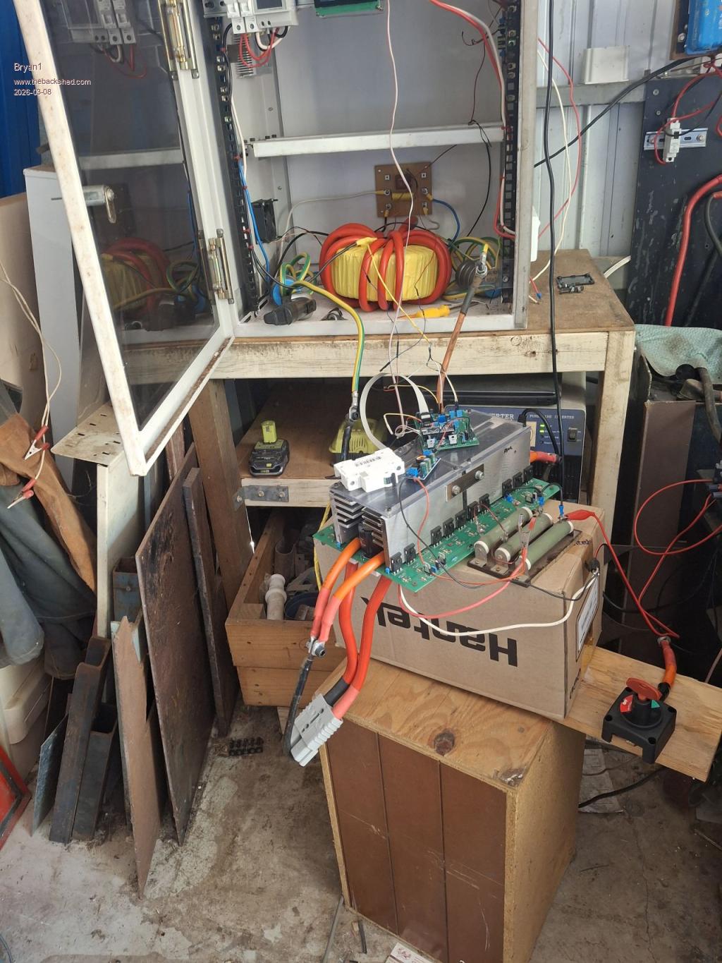 Now I have changed out R54 for 1K and soldered in a short for the 120 ohm resistor so those changes have happened. |
||||
| phil99 Guru Joined: 11/02/2018 Location: AustraliaPosts: 3293 |
V = I * R = 200mA * 67Ω = 13.4 Volts drop across the resistors. Measure it if you want to be sure. 28V - 13.4V = 14.6 Volts. That is all your inverter has to work with. You are getting all it can give. You need to bypass the cap. charging resistor after the caps are charged and before starting the inverter. |
||||
| Bryan1 Guru Joined: 22/02/2006 Location: AustraliaPosts: 2101 |
Well just tried it out and I made an inline switch to supply VBat, so once the BV got to the voltage of the psu I closed the switch then turned on the nano. It dropped to 10 volts with only 1.7 AC volts at VS1 and VS2 Now measured those fast diodes when was running now the one where the arrows pointed on the left was 17 volts and the other one 7 volts. Now the TIP31 pins were 8 volts 9 volts 8 volts I did do a test with the choke cables left off and the result was the same 1.7 AC volts so yes the problem looks to be in the power board. Edited 2026-03-08 13:36 by Bryan1 |
||||
| tinyt Guru Joined: 12/11/2017 Location: United StatesPosts: 559 |
Verify that D1, D7, D18, and D19 are at the corners of the PCB. If they are, use your scope CH1 probe and do the following VERY CAREFULLY: 1. probe GND to power board ground probe tip to D1. capture and post scope screen. 2. probe GND to power board ground probe tip to D7. capture and post scope screen. 3. probe GND to power board VS1 probe tip to D18. capture and post scope screen. 4. probe GND to power board VS2 probe tip to D19. capture and post scope screen. |
||||
| Bryan1 Guru Joined: 22/02/2006 Location: AustraliaPosts: 2101 |
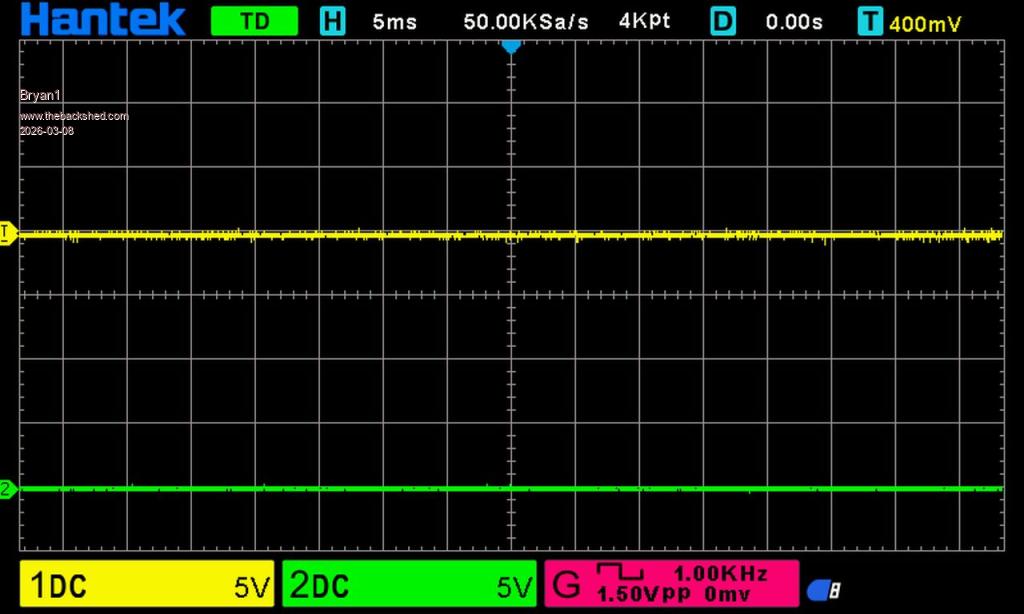
Ok got some scope pic's but it does help to read properly as I probed D1,D7,D18,D19 with gnd going to vbat ground D1 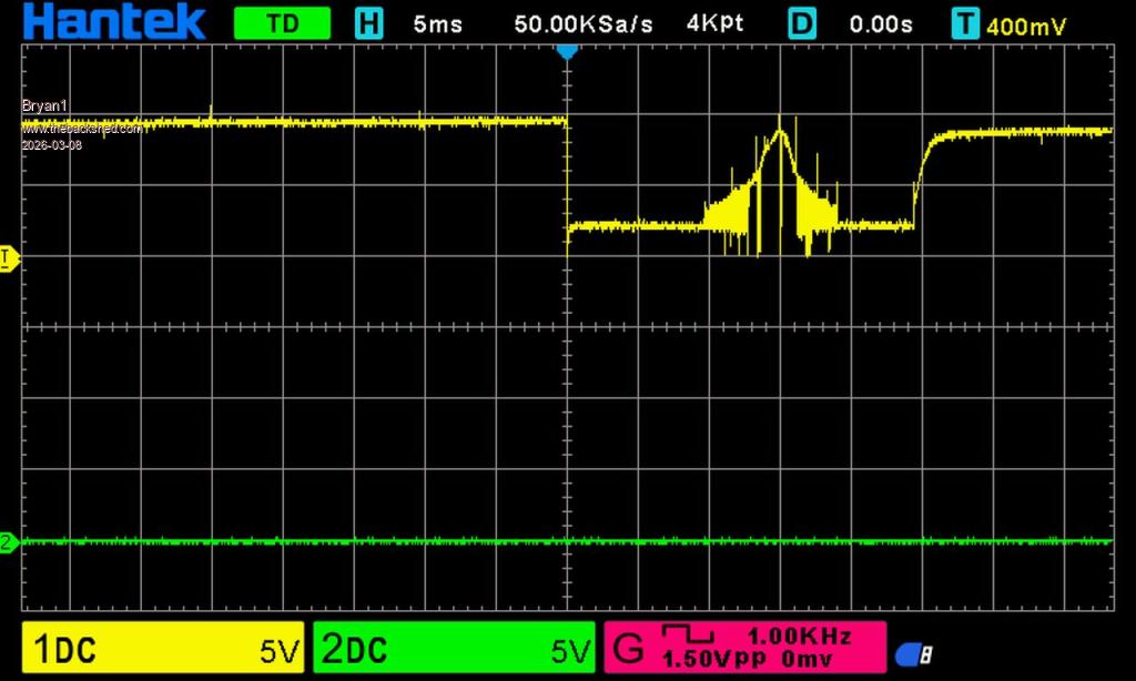 D7 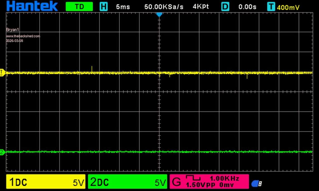 D18  D19 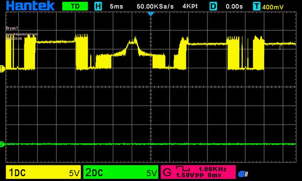 Now I will go and 3 and 4 like I should of. |
||||
| Bryan1 Guru Joined: 22/02/2006 Location: AustraliaPosts: 2101 |
3.  4. 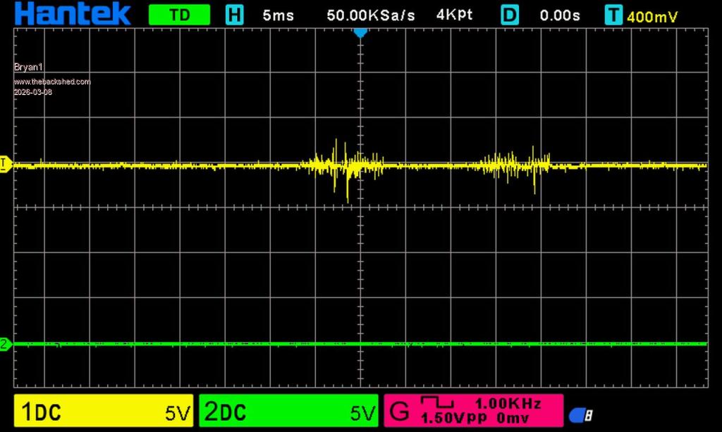 |
||||
| tinyt Guru Joined: 12/11/2017 Location: United StatesPosts: 559 |
With the board un-powered, measure the resistance of R1, R26, R27, and R52. They are close to the TIP41/TIP42 pairs and all should measure around 20 ohms. |
||||
| Bryan1 Guru Joined: 22/02/2006 Location: AustraliaPosts: 2101 |
OK got some scope pic's of the gate on each leg Gate of Q3 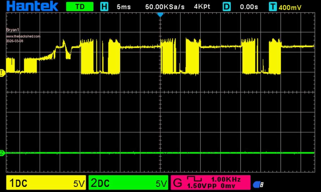 Gate of Q14 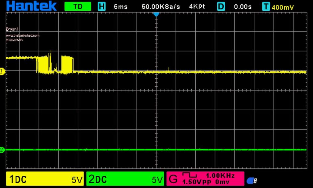 Gate of Q25 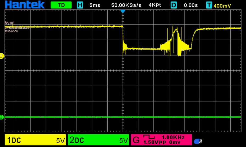 Gate of Q19 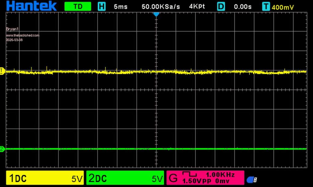 R1, R26, R27 and R52 all measure 20 ohms |
||||
| tinyt Guru Joined: 12/11/2017 Location: United StatesPosts: 559 |
Looks like Q3 - Q8 mosfets are receiving the right gate signals. Remove Q16, Q17, Q32 and verify that they are TIP41. Remove Q15, Q18, Q32 and verify that they are TIP42. Measure resistance between gate and source/drain of Q14, Q19, and Q25. |
||||
| The Back Shed's forum code is written, and hosted, in Australia. | © JAQ Software 2026 |
