
|
|
Forum Index : Windmills : Working on a 10 hp motorconversion
| Author | Message | ||||
oztules Guru Joined: 26/07/2007 Location: AustraliaPosts: 1686 |
Peter, Whilst it looks good on paper, I think there are easier ways to achieve it. The problems I see are from induced noise. As the power increases, the level of noise from the switching on and off of the power diodes will induce a fair degree of induced noise in the pickup coil. Your cunning idea of using the anti-parallel may help only to make matters worse. They would clip both the noise and associated harmonics and your signal, all to the same voltage. This would get worse as the power went up. Then you are faced with filtering out by frequency only. The amplitudes of the noise and the signal may well be all clipped to the same amplitude. You would need one of Doms first order low pass filters, or perhaps a second order butterworth filter.... but even then, your frequency is ranging which means first order is all you may be able to get away with. I think the simplest and least noisy solution lies with the good old PSU's.... yes them again. If you pull the fans out, you will find hall a effect latch IC. This is usually an open collector arragement. Just plant one of these anywhere where they can read a passing magnetic field, (or just bury it in one of the slots. Now you have a fixed amplitude square wave signal at quite decent voltages. The only thing to change as it speeds up is the frequency, the amplitude remains the same.(Up to vmax for the hall IC) So problem solved with the good old psu again.... at least thats how I am going to do it when I get this infernal beast of mine up in the air again. ...........oztules Village idiot...or... just another hack out of his depth |
||||
| oztules Guru Joined: 26/07/2007 Location: AustraliaPosts: 1686 |
Now for the Furling , You said: "Yes, the key on the back is there so I can install a disc brake on it, as Bruce has done with his F&P. I like the idea of 'belts and braces' safety. Furling plus a way of mechanically positively stopping the blade. This would also be handy during raising and lowering of the tower. I'm also keeping in mind Oztules' method (rather: Southern Cross method) of furling/stopping the windturbine, but at the moment I'm partial to a braking mechanism. " And I said, ..... hell I had better go outside and take some pics of the furling as promised. The furling stuff is just loosely assembled to take some pics. But you should get the idea. Here we have no imposed furl position. It is free to self furl, but we have no control in this guise. 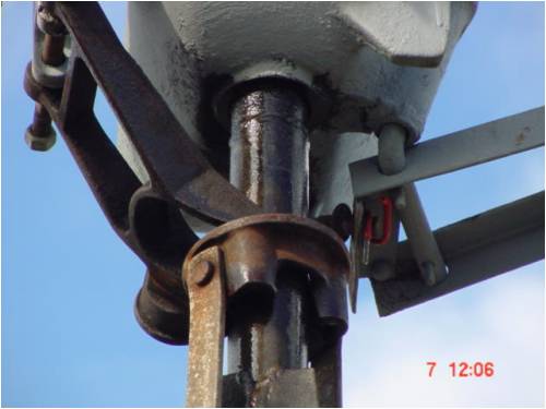
Now I have pulled the handle down from on the ground (this thing is only 12 feet tall) and it has pushed the forks up towards the body, This in turn pushes the tail around a bit. It can still furl by itself further, but I have now hobbled it from full power. At best it will always be 30 degrees off the wind 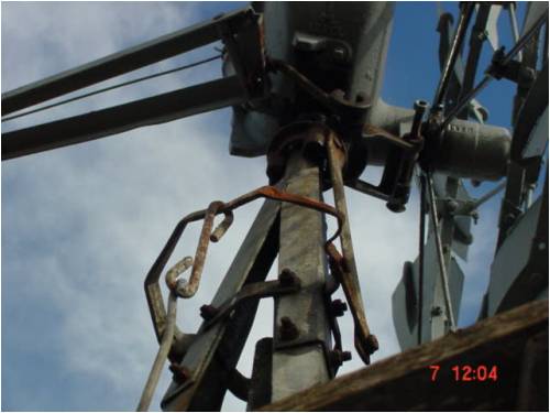
Now we have pulled the handle all the way down, and it furls it up fully. This machine has no load on it at all. I am currently building a pump for it. So it is left in the fully furled position. Yesterday we had 60-70km winds, the mill was mostly still unless a gust from a different direction turned up. Then it re-oriented and was still again. No stress or strain on anything. 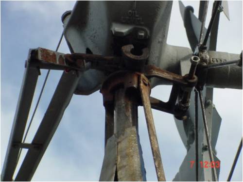
The handle is the steel horizontal bar about a foot below the triangle wood platform. To furl it just pull the handle and hook the hook onto one of the horizontals of the lattice. 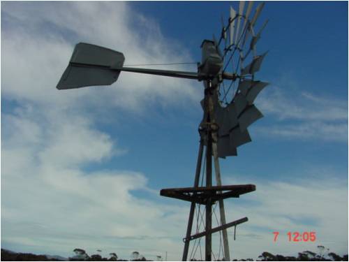
I hope that is enough to get the feel for it. If you need further detail/pics of it, then just say so. ........oztules Village idiot...or... just another hack out of his depth |
||||
| Dinges Senior Member Joined: 04/01/2008 Location: AlbaniaPosts: 510 |
Oztules, I had considered the main rectifier too but I hadn't expected it to create such a noisy environment. The rectifiers *are* non-linear, of course... But I thought an isolated pick-up winding wouldn't suffer too much from it. Then again, it would be very tightly coupled to the power-generating winding... Technically one could make the pickup winding with 10-50-100 turns, or whatever is suitable, of thin wire. That may drown out the noise. (edit: or it may transform the noise voltage up too... Hm...) But it also quickly loses its initial elegance of one (or a few) pickup winding(s). Filtering would be a possibility, yes. But my filter design knowledge isn't what it used to be...  Anything beyond a simple first-order RC or LC filter would need some delving into books. Anything beyond a simple first-order RC or LC filter would need some delving into books.
I had considered a Hall-effect sensor too but thought the pickup winding would be even easier. One problem I see with installing the Hall sensor: it's a semiconductor and thus can't stand too high temperatures. If I'd install it *before* the drying/varnishing cycle, it'd likely die from excessive temperature. So it'd have to be installed afterwards, using some epoxy perhaps. The good news is, the magnets of the rotor stick out about 10 mm on each side of the stator; that excess could be used to drive the Hall sensor, it'd make for easier mounting of the sensor. A few drops of epoxy to glue the Hall sensor on one leg of the coils should work, I expect. The other problem I have is that I have plenty of Hall-effect sensors but none I've seen bear any marking. Some have 3 leads, others have 4. Would be a matter of trial and error to find out which lead does what. Thanks for your thoughts. And once more you manage to shoot down one of my creative brainwaves.  With friends like that... who needs enemies... With friends like that... who needs enemies... |
||||
| Dinges Senior Member Joined: 04/01/2008 Location: AlbaniaPosts: 510 |
Oztules, Thanks for the detailed pictures of the Southern Cross furling/stopping mechanism, it's much appreciated. It's beginning to make sense to me how it works. Clever mechanism, since it still furls normally as it's (partly) manually furled. Now I'm thinking about ways of adding something like that to the 'normal' (Hugh Piggot e.a.) furling system. Could probably be easily done with some steel cable and a pulley. Let's see... 1) normal furling 2) manual furling 3) manual brake. There's no better kill than overkill, especially when dealing with a turbine you want to stop ASAP. Food for thought. Let me ponder for a while and I may present some sketches/ideas in this forum (only to have them shot down by you...) |
||||
| oztules Guru Joined: 26/07/2007 Location: AustraliaPosts: 1686 |
Play with the hall sensor in the fans. Three wires are pos, neg, signal output. Very simple to use. I found that they can be 3 inches away from the neo's and still switch perfectly. (I did this when I was experimenting with using the axial flux as a motor. These things are incredibly easy to use.) So mounting them is dead simple. Look up; http://www.digchip.com/datasheets/parts/datasheet/029/A3161E LT.php This is probably whats in your fans. The loop you proposed will still work though, but rc filter will be necessary. Perhaps the anti-parallel after the filter will be alright. Otherwise you still have rising amplitude with rpm. It will depend on how you use the output as to what this means.... good or bad. I know Flux has described solutions for using the freq of the mill to tacho chips, and has also found that noise can be difficult to eliminate sometimes. Thats the noise that will be induced into the pickup coil. I just think (after playing with them) that a better way without noise and associated filtering, is with the halls. ...... Just thinking, if you still have your little axial, use the scope and watch what happens when cut-in conduction takes place. My frequency meter has heart failure as soon as cut in occurs. Before that, using freq to measure rpm looked so damn simple. An rc filter can solve this though, but I still like Halls. I'll be only too happy to steal your plans and put them to use (and tell everyone what a good idea I had too) 
.....oztules Village idiot...or... just another hack out of his depth |
||||
| Dinges Senior Member Joined: 04/01/2008 Location: AlbaniaPosts: 510 |
Oztules, Was looking around in the parts bin with Hall sensors and found two identical ones on a piece of print with wiring. The wires were colour coded so a piece of cake to connect it.
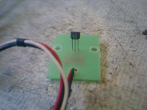
Nearest power source was a 6V battery. Quickly wired it up. Digital multimeter (DMM) is set to diode test. With no magnetic field present it measures infinite resistance: 
Grabbed the nearest magnets to test. With a magnetic field: 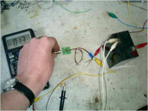
Ok, seems to work perfectly up to a distance of about 30 mm with these tiny magnets, and it only responds to one particular magnetic polarity, not just the presence of any magnetic pole. BTW, about 1/2 a year ago I tried to test these same Hall sensors. I expected them to give a high/low output in the presence/absence of a magnetic field, i.e. a digital signal and didn't see anything. Didn't realize they had open-collector outputs...
Current plan: mount both Hall sensors in the stator (one spare sensor in case something 'happens' to the first sensor). That magic smoke is just waiting to get out and I know myself too well... I'll likely also add a pickup winding. Better have it and not need it than the other way around. And a temperature sensor, of course. As far as stealing my plans goes: I'd consider it an honour if you stole them!  |
||||
| Dinges Senior Member Joined: 04/01/2008 Location: AlbaniaPosts: 510 |
*sigh* Epoxy, epoxy, my kingdom for some epoxy... Work has been progressing on the rotor of the 10 hp conversion. All the magnets have been glued on. 36 pcs. of N42 50x25x12 mm. Glued on 6 pieces at a time, so 6 glueing sessions in total. All in all it went pretty well considering my initial fears. The ridges that were milled on the rotor were a very big help when glueing the magnets, as one only need to worry about locating the magnets in the longitudinal direction. 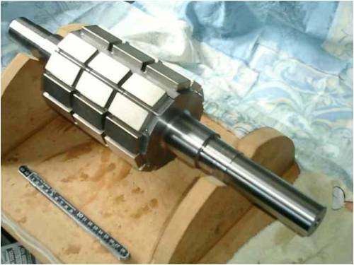
After the magnets were glued on they were degreased, sanded and degreased again (to remove any amine blush from the epoxy, and to provide better mechanical adhesion). A piece of glasscloth (80 gram/m^2) was cut to size and wrapped around the rotor. The start was fixed with a few dabs of cyano-acrylate glue. Epoxy was then applied to the glasscloth so the cloth would be attached to the magnets on the rotor. The glasscloth is some extra insurance against the magnets flying off. I don't really think it's needed but if I didn't, Ron said he'd no longer be my friend. The things one does to keep him happy... I don't have a picture of the glasscloth laminated to the magnets. You'll have to take my word for it that it's really there. The epoxy was left to cure for two hours and then the mould was added to cast the entire rotor (yeah, right, the *entire* rotor... read on) in epoxy. 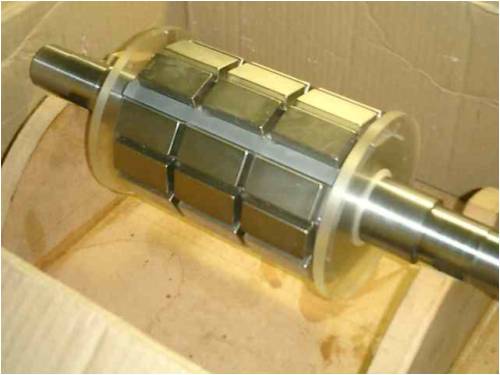
The mould is made from two endpieces of 8 mm plexiglass, turned to size. Over the endplates a piece of plastic was attached. 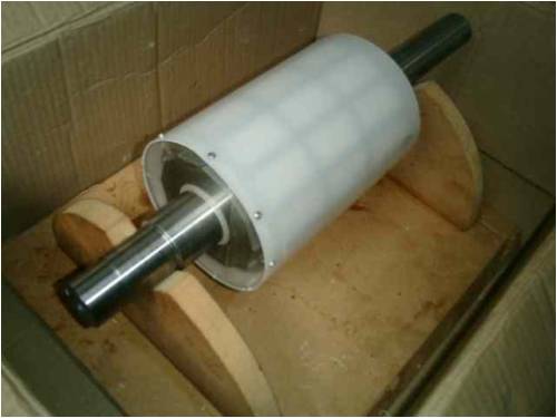
The mould was installed after the glasscloth lamination was partially cured, the rotor was stood up vertically. Then the casting began. Thanks to proper preparation this went pretty smooth. Except that halfway during the casting I began to notice the supply of epoxy was diminishing rapidly. But, no worries! I had calculated beforehand how much epoxy I needed and I had twice as much as I needed. Or so I thought. Till the last drop of epoxy was used, and the rotor was only 2/3 cast. *sigh*. Why doesn't reality conform to my calculations ?! I still don't know what went wrong. I verified my calculations again and I *should* have had plenty of epoxy to finish the job, but the picture tells another story. 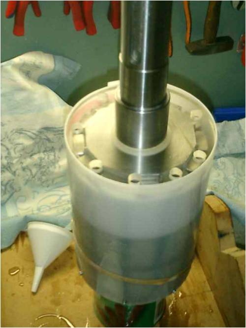
It's not a big deal, it will just delay finishing the rotor some more (I had hoped to turn it to size this weekend). It means that after this epoxy is cured it'll have to be cleaned and sanded again (in all the tiny nooks and crannies) before the last bit can be cast. I'd have preferred to cast the rotor 'wet on wet', it'd give a better endresult and take less effort. The extra cleaning and sanding that will be needed now is work that shouldn't have been necessary. Either way it shouldn't have too much detrimental effect to the endproduct. Bugger. It all could have gone so perfectly smooth. Things like this annoy me to the core as it's extra unnecessary work.
Stay tuned as Peter tries to solve the mess he created. Or, as my chef once said: 'Peter is an excellent crisis manager. Too bad he's also the cause of all the crises.' |
||||
CraziestOzzy Senior Member Joined: 11/07/2008 Location: AustraliaPosts: 152 |
Sweet job 
Big bummer about the wait for the next (dare I say it) epoxy job. Just a question for you...is there any need/plan to balance the rotor once all is dried and finnished? http://cr4.globalspec.com/member?u=25757 http://www.instructables.com/member/OzzyRoo/ |
||||
readyakira Senior Member Joined: 17/07/2008 Location: United StatesPosts: 114 |
For the rpm detection you could use something like a transmission uses... a gear with a magnetic pickup. Looks like you have plenty of shaft there to locate one far enough away to avoid magnetic interference. Let me look for a link to what I am talking about.... Found it... now keep in mind they talk alot about transmissions but the principles are the same... http://www.jagsthatrun.com/V8-chapters/V8-tpi-Speed-Sensors. pdf I actually used the rear end conversion kit on my s-10 when I installed an older transmission in it. BTW you can machine yourself a gear similar and only put one tooth on it then every revolution would be one pulse. or you could put several on it to be able to duplicate the approximate phases you are using and be able to isolate it from that power. The link is a pdf so it may be easier to right click it and save as. Also on that site is a link to where you can buy the sensors and maybe even the gear, but I think that is going to have a small ID compared to the OD on your shaft. Don't you think Free/Renewable energy should be mandatory in new buildings? |
||||
| oztules Guru Joined: 26/07/2007 Location: AustraliaPosts: 1686 |
Well Peter, Just another great looking project to come from the "house of Dinges" Now let me see, calculated twice as much as needed, but only got 2/3 done..... so, calculations are out by ..lemme see some 300% Somehow (at some lower level), this makes me feel better about some of my projects that didn't quite measure up to expectations. Might be time to reprogram the trusty abacus.... now how many turns per coil was that?
Beautiful job Peter. Will be looking forward to the output figures of this beast. 
.......oztules/3 Village idiot...or... just another hack out of his depth |
||||
| Dinges Senior Member Joined: 04/01/2008 Location: AlbaniaPosts: 510 |
CraziestOzzy, I'm in doubt about the balancing. The running speed will be pretty low, I expect an absolute maximum of 300 RPM. People I talk to say it won't be needed, my motor manual says it should be over 100 RPM and with the length-to-diameter of this motor. The best thing, of course, would be to balance it, at least statically. Balancing is always easier on the bearings and the bearings are the only thing of this conversion that can wear. I think in the end I'll balance it by drilling holes in the steel rotor in strategic places. Readyakira, Thanks for the links. I'll likely be using the two Hall sensors that were shown earlier in the thread. I'm aware of the fact that there exist purpose-built Hall sensor modules to measure RPM, but since I already have magnets on the rotor that extend beyond the stator, the easiest thing would be to use that magnetic field. No extra pickup-rings would then be needed, just would have to epoxy a Hall sensor somewhere in/on the stator. Oztules, "so, calculations are out by ..lemme see some 300%". Are you trying to tell me something here ?  I don't make many errors but at least when I do, they're big: factor 3 (or factor 4, as in the case of rewinding the 500 W conversion where cut-in voltage initially ended up at 1000 RPM instead of 250 RPM). I don't make many errors but at least when I do, they're big: factor 3 (or factor 4, as in the case of rewinding the 500 W conversion where cut-in voltage initially ended up at 1000 RPM instead of 250 RPM).
On the bright side: the errors are getting progressively smaller. From a factor 4, to now a factor 3. So, by 2nd next project I will be spot-on. Peter. 'extrapolation is a puppy the size of an elephant' |
||||
| CraziestOzzy Senior Member Joined: 11/07/2008 Location: AustraliaPosts: 152 |
I thought that may be the case...not a real requirement for a low RPM, but nice to do it for ease of wear. I initially popped the question, as I am curious how your work applies to my jumbled project http://cr4.globalspec.com/member?u=25757 http://www.instructables.com/member/OzzyRoo/ |
||||
| Dinges Senior Member Joined: 04/01/2008 Location: AlbaniaPosts: 510 |
Guess it's about time for an update on the 10hp conversion as it has been a while. Didn't have much time to play with it due to other priorities, but finally got a chance to finish it. Casting the epoxy had already finished a few months ago. There are some air inclusions ('foam') present where the two castings touch (I wanted to cast in one piece but ran out of epoxy, so the last part had to be cast after the first part had set and was prepared/cleaned again), but the air pockets are much smaller and less of an issue than I had feared, so I didn't bother to re-touch them as I initially planned. Below is a picture of the rotor after casting but before machining to final size. 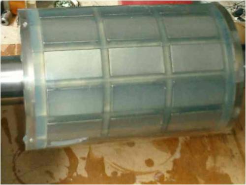
After a hiatus of a few months, last week the rotor was finally turned to size, see image below. The outer diameter is now 129.0 mm, just as the original (induction motor) rotor was. The inside diameter of the stator is 130.0 mm. 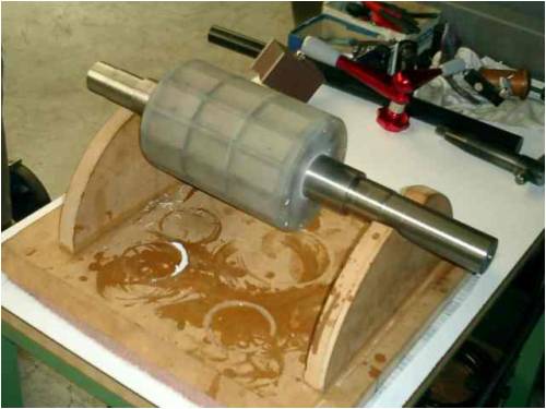
The next step is getting 2 new bearings (6308-2RS), installing them and then carefully inserting the rotor into the stator for a test run. A single-turn testwinding has already been installed in the stator, to determine RPM/V of the rotor-stator combination. I'll admit, not much got done over the past few months. But the above report should satisfy the curious. (you reading, Vawtman ?) On an entirely different note: after a long time of reading, thinking, sketching and more reading on recumbent bikes and trying to design my own one, I finally gave in and decided to cheat and buy a (slightly used) Challenge Hurricane. Here she is, in all her glory: 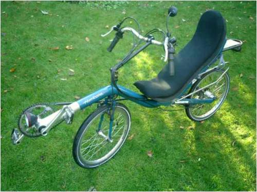
Riding it is more fun than a barrel of monkeys. Well, it wasn't for the first two days, as I was about to go to the bicycle shop to buy me a set of training wheels. But, finally, I managed to stay on it for more than 0.5 seconds without falling off. And by now, riding it has become pretty much 2nd nature. A sheer joy to ride, incomparable to plain (delta-frame) bikes. Much more comfortable and faster, less effort, less fatigue. There's still a bit of work to do on it to make it 100% to my liking (fenders, cover for the crankwheel, some better chainprotection, better lights) but those are things to deal with in the future. Only thing I regret is not getting a recumbent 10 years sooner. I can definitely recommend it to anyone, or at least to try one out. Don't get frustrated if you fall off (a lot...  ) in the beginning, once you are past that I doubt you will ever switch back to an upright bike. ) in the beginning, once you are past that I doubt you will ever switch back to an upright bike.
Peter. |
||||
| oztules Guru Joined: 26/07/2007 Location: AustraliaPosts: 1686 |
.......Bollocks...... the curious want to know turns/volt/rpm, how many times you jamb your fingers trying to get the thing into the stator, and how you manage to miscalculate the turns and rewire for a lower voltage than planned.... thats what the curious want to know... 
Keen to see what she will do I must say. It's only been near half a year hiatus. ....you sure dats a bike????!!!. Not only does the water go down the drain the wrong way up there, but they build the bikes upside down too 
.........oztules... where the water goes down the drain the right way, and they build bikes with the pedals under your bum. Village idiot...or... just another hack out of his depth |
||||
| Gizmo Admin Group Joined: 05/06/2004 Location: AustraliaPosts: 5182 |
That seat sure looks comfy! The best time to plant a tree was twenty years ago, the second best time is right now. JAQ |
||||
| Dinges Senior Member Joined: 04/01/2008 Location: AlbaniaPosts: 510 |
Finally... Some more work got done on the 10 hp motorconversion 'Blue monster'. After the rotor got turned to final dimensions a few weeks ago I installed fresh new bearings: 2 pieces of 6308-2RS1. 40 mm shaft diameter, 90 mm outside diameter. This took a bit of effort heating them with a hotplate and persuading them to move with a large hammer but I got them installed in the end. Then, as I was about to insert the rotor in the stator, I had a good look at the endbells... and noticed the bearing houses were not the same size !  . Despite all the preparation and care I still managed to miss this. Argh! . Despite all the preparation and care I still managed to miss this. Argh!
So, out came the trusty puller. Removed one of the bearings and replaced it with the proper one, a 6208 (80mm OD). (I may pull both bearings and swap them later, so that the largest one that will take all of the axial load will be at the rear. This means swapping the endbells too but that's no problem.) 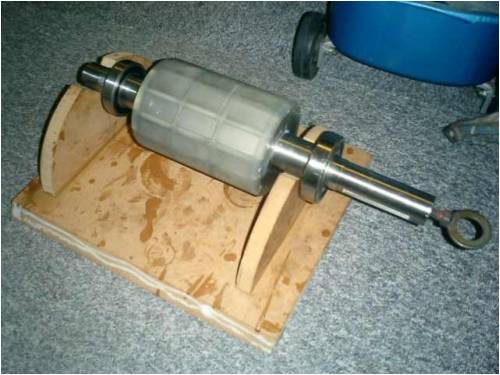
Next step was inserting the rotor. With a manual hoist this went relatively easy but there was definitely a lot of pull from the rotor: the stator was literally trying to suck it in. This is NOT a rotor that I'd want to 'throw' into the stator. Maybe I'm just a coward... but considering that there's for 300E worth of magnets, 100E of steel, 100E worth of bearings, and a lot of manhours invested in it... You'll probably get the point. 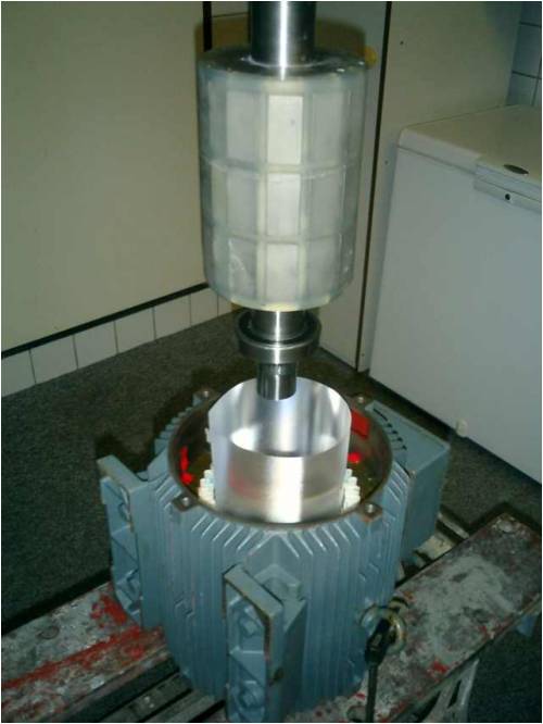
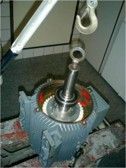
After installing the endbells was the moment supr�me: testing it for cogging. For the past few days I was worried about this. I *knew* everything *should* be fine... but what if I missed something ? What if the theory isn't correct ? A calculation error? A machining error? Etc. I think Zubbly was right when he told me I worried too much... because it didn't cog! Not even the slightest little bitty bit of cogging was detectable. Hurray! No cogging, but of course there is quite a bit of iron loss; the rotor turns pretty hard, I'll be making measurements of this later to determine the exact amount of iron loss. It's not like an axial flux that, when you give it a swing, keeps rotating for the next minute. But I have little doubt a 4-5 m prop will have trouble starting it up. Next step is building a setup (with drive motor and VFD) to determine RPM/V of the generator to help decide on how many turns per coil will be needed. So far, when manually rotating at about 65 RPM, I get about .5Vac from the single-turn test coils, so about 125 RPM/V/turn. On the scope the waveshape looks reasonably sinusoid; there's some 3rd harmonic present which 'clips' the sine tops some, but it's much less severe than I had expected. Peter, in a Droopy voice: "I'm happy" Edit: it takes about 7N (0.7kgf) at a 0.21m arm to overcome iron loss and bearing loss and very slowly rotate, so Mdrag=~1.5Nm. Better measurements to arrive hopefully soon. |
||||
SparWeb Senior Member Joined: 17/04/2008 Location: CanadaPosts: 196 |
Peter, I'd like to be the first to congratulate you! Getting these biggies together is dramatic when the magnetic forces take hold, and SO satisfying when you turn that shaft and know in your fingers that you've done it right!
Before you go creating a VFD, try just pulling with a string around the shaft, and a voltmeter on the output leads. You'll be surprised how much this will tell you, and it's so easy to do. If you also use a spring scale on the string, you can get the ballpark figure for the iron loss, too. Remember my complicated analysis pages from 6 months ago? Well I've got them fixed up now, and the theoretical matches the test data from my 3HP GE, and the Toshiba on my bench is VERRRRY promising. And I don't need a VFD to do it. I may put it on the lathe in the shop at work here, just to confirm that the math holds true. Then again, who DOESN'T need a variable frequency drive setup in their own garage? Steven T. Fahey |
||||
| oztules Guru Joined: 26/07/2007 Location: AustraliaPosts: 1686 |
Great to see that there is no cogging, and the torque requirements to get it started are not too bad for the amount of magnet in there either. You've done a fine job so far, just don't repeat the "blueboy" calculations..... hopefully the bearing mismatch is the last of the gremlins for you with this. so.. Voltage?.......Turns?...... thickness??.... the devils in the details
..........oztules Village idiot...or... just another hack out of his depth |
||||
| Dinges Senior Member Joined: 04/01/2008 Location: AlbaniaPosts: 510 |
Steven, thanks. Yes, it's always an exciting moment when you spin that shaft for the first time; will it need a pipe wrench to turn, or just two fingers... As I was inserting the rotor I tried to take my weight off the workmate, but the rotor immediately tried to lift both stator and workmate (total weight ~55 kg) off the floor...
My thought! Every house needs at least one! Looking forward to published results of your model. Would be a nice way to predict generator voltage and power of conversions. I now use 100W/cubic inch as estimator of power output for conversions. None of mine have attained Zubbly's 150W/cubic inch so far. Maybe my airgaps are larger, or I'm testing/rating them at lower RPMs than Z. Oztules, I just checked a bit more... of the 1.5Nm startup torque, 0.3Nm is caused by the bearing seals. But yes, should be easily overcome by any prop. [QUOTe=oztules]just don't repeat the "blueboy" calculations..... hopefully the bearing mismatch is the last of the gremlins for you with this. Darn. You have good memory. And I was only off by a factor 4 too... Seriously, that's why I'm glad I did that small conversion first, as it allows one to learn before investing major time and effort in 'the big one'. You should have seen the look on my face when I noticed I had installed the wrong bearing. Mr. Murphy is always looking over your shoulder... Too much attention for detail (calculating bearing loads, C0, P0, lifetime calculations, seal friction, etc), too little attention for the basic things (like correct bearing size...). . I should have measured *both* endbells. And if the original bearings still had been in place when I got the motor I'd have easily spotted the difference in size too. So looks like Murphy was really lurking in the background. (I find that idea more comforting than blaming my own incompetence )
Preliminary results yield 125 RPM/V/turn (for 6 single-turn coils). More accurate measurements to follow when I've build a small measurement setup. Peter. |
||||
| oztules Guru Joined: 26/07/2007 Location: AustraliaPosts: 1686 |
Dinges, You have probably mentioned this before, but what voltage are you wiring for (nominally). Was 125rpm/v for a single six coil phase? (I assume AC rms.) I keep my variable frequency drive device.... up the windmill tower....I do find it difficult to dial in the frequency.... seems to be wind dependent
......oztules (village idiot) Village idiot...or... just another hack out of his depth |
||||
| The Back Shed's forum code is written, and hosted, in Australia. | © JAQ Software 2026 |
