
|
|
Forum Index : Windmills : 36 slot stator and a long way to go...lol
| Author | Message | ||||
CraziestOzzy Senior Member Joined: 11/07/2008 Location: AustraliaPosts: 152 |
I saw the add you posted a few days back and thought the inverter would be long gone. Would love to grab it and give it a home and clean the cobwebs off it .  http://cr4.globalspec.com/member?u=25757 http://www.instructables.com/member/OzzyRoo/ |
||||
| Dinges Senior Member Joined: 04/01/2008 Location: AlbaniaPosts: 510 |
Personally I wouldn't use the laminations for the rotor. If it were mine I'd machine an entire new rotor out of steel and mount the magnets on that. Seems easier and better to me, but you need some machining capability to do it: http://www.anotherpower.com/gallery/album69/blue_boy_shaft_a nd_rotor_core_finished As far as the number of poles go; I assume you will be turning it into a three-phase generator. With 36 stator slots that gives you the option of a 12 pole, 6 pole, 4 pole and 2 pole. For a slow-running genny 12 pole would be best, followed by 6 pole. Whether you can turn it into a 12-pole depends on the size of your magnets: are they small enough so you can install 12 poles on the rotor ? If not, 6 pole would be the next option (if you don't want to resort to very exotic winding schemes). |
||||
| CraziestOzzy Senior Member Joined: 11/07/2008 Location: AustraliaPosts: 152 |
I have not got the magnets yet. I am considering using the Australian supplier I ran across, Freenergy. Will have a look at the rotor this afternoon and figure out how to fit 12 poles on the rotor available. Thanks http://cr4.globalspec.com/member?u=25757 http://www.instructables.com/member/OzzyRoo/ |
||||
AMUN-RA Senior Member Joined: 10/03/2007 Location: AustraliaPosts: 144 |
co look in yellow pages under solar power equipment and supplies the 1300 no rings my mobile if you want that inverter Mick Every day the sun shines & gravity sucks= free energy. |
||||
| CraziestOzzy Senior Member Joined: 11/07/2008 Location: AustraliaPosts: 152 |
Rotor Design I may be able to get a friend in Brisbane to laser cut laminations for a rotor and keep the 36 slot stator and remain on budget...which isn't much 
I have included the rotor I have designed (last image below) with the proposed positioning of the magnets. I have kept the scale of the rotor within the dimensions of my stator which is being restored at this moment. The current thought is to purchase 36 neodymium magnets (N45) at 5mm x 20mm x 20mm for each rotor. The cost being met by recycling copper from old motors I have stripped. I may have several (first image below) individual rotors (coloured black) fixed to the one axial shaft (coloured green), with the thickness of each rotor being determined by the depth of the magnets (a rotor 40mm deep/thick would require two sets of magnets, which would make a total of 72 magnets per rotor) arranged in the following manner... 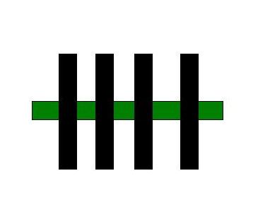
The last image below shows the positioning of the magnets for my rotor. I found a link on this or another forum to 3d software "freeware" that helped me design this image... design software here 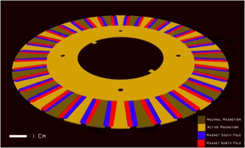
There are 18 rotor teeth (labeled as "active magnetism", coloured orange) that have effective magnetic flux towards the stator. Nine teeth are south pole (blue) orientated and the other 9 are north (red). There are 18 remaining rotor teeth (labeled as "neutral magnetism", coloured brown)that have no effective magnetic flux towards the stator. There is room for improvement... ...remove the "neutral" teeth and insert larger magnets - but cost will stop me here I think. ...enlarge the "active" teeth size to accommodate the increase in magnetic flux created by larger magnets. Dumbass question, is this an 18 pole rotor? Any thoughts on this proposed setup using my 36 slot stator would be great  http://cr4.globalspec.com/member?u=25757 http://www.instructables.com/member/OzzyRoo/ |
||||
oztules Guru Joined: 26/07/2007 Location: AustraliaPosts: 1686 |
I'm not sure I'm seeing this in my head right. Dinges is probably the man to work these magnetic thinggy's out... So I will make some observations so that he may sort us both out perhaps... should he wish to comment at all. If someone is going to cut the laminates, why not cut them to do dinges style of rotor (in laminates instead of solid).... less material,cheap steel, and better results, standard magnets etc. I think it is 18 pole as you have drawn it, but pole leakage will be greater than using a normal orientation, and if you are going to custom cut, why not cut for best results. Burying magnets in the material will never give the same results as surface mounts apparently. To add insult to injury, the cogging would be a real problem. Just my thoughts on it... and I might not be "getting it" ........... oztules Village idiot...or... just another hack out of his depth |
||||
| Dinges Senior Member Joined: 04/01/2008 Location: AlbaniaPosts: 510 |
Hey Craziest, Oztules basically said it all. Yes, it is an 18 pole rotor. But with 36 stator slots (and assuming you want it to be a 3-phase generator) rewinding wouldn't be straightforward. http://www.powercroco.de/Kombinationstabelle.html The above link is to a (huge) site mostly for small CD-ROM RC-motors but much of the theory applies to our gennies too. I checked and you can theoretically rewind for 18 poles/36 stator slots (see the handy calculator near the top of that page) but only two phases, it seems. I don't see the advantage of using laminates to mount the permanent magnets (PM) into, as there's no changing magnetic flux these laminates see there will be no eddy current losses. A solid steel rotor core should work just as well and be much easier to manufacture. Then there's the cogging you'd have to take into account. I won't go into detail here because the next point will (or: should ) stop this plan immediately...
Oztules was right again (ouch, hurts to say that aloud) when he mentioned the flux leakage. I ran a quick FEMM (magnetics finite element software) to make that visual: 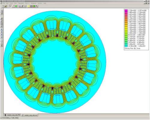
The full, high-resolution images can be found here:http://picasaweb.google.com/motorconversion/Temp Notice how much of the magnetic flux gets 'shorted' inside the rotor ? About 2/3, by my estimation. Relatively little flux leaves the rotor to enter into the stator (where it would be actually useful). It would make very bad use of the magnets. |
||||
| CraziestOzzy Senior Member Joined: 11/07/2008 Location: AustraliaPosts: 152 |
yeah, quick reply. Cheers...i was thinking of skewing the stator teeth to reduce cogging and have laminates as mentioned...will look at Dinges thoughts when I come back home and read both your thoughts more thoroughly. Much appreciated Oztules and Dinges. http://cr4.globalspec.com/member?u=25757 http://www.instructables.com/member/OzzyRoo/ |
||||
| CraziestOzzy Senior Member Joined: 11/07/2008 Location: AustraliaPosts: 152 |
Well, had a good read at what you mentioned Dinges - big thanks to Oztules and Dinges again ...I actually thought the flux would be concentrated on the outer periphery of the rotor, rather than to the core...guess I am wrong judging by your quick analysis using FEMM.
The use of laminates with my playing around with magnets on the bench showed to me that magnetism is "enhanced" or concentrated through the laminates. But looking at your FEMM diagram, I can see that I do not need laminates for the rotor as the stator laminates already do the job of attracting the magnetic flux from the rotor magnets. Going to have to see if I can round up that (FEMM) or similar software, to figure out how to maximise my 36 slot stator into a genny...and off to figure out a simpler means of cramming a million big magnets into a one piece aluminium rotor. http://cr4.globalspec.com/member?u=25757 http://www.instructables.com/member/OzzyRoo/ |
||||
| pntrbl Newbie Joined: 12/07/2008 Location: United StatesPosts: 32 |
As I've been learning about generators and windmills in general I've quite often found myself trying to visual where the fluxlines will be. Would be a useful thing to know but it ain't like you can see them .... But apparently Dinges can! So I googled FEMM real quick, found the homepage, and then checked out the reference manual, which promptly scared the bejeesus out of me! 155 pages and it starts off with differential equations? I dunno if I'm smart enough for that. Is it hard to use? Should I download it and see what blows up? LOL! SP |
||||
| oztules Guru Joined: 26/07/2007 Location: AustraliaPosts: 1686 |
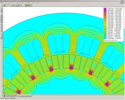
CraziestOzzy. It does not matter for these purposes (rotor) whether you use laminates or solid steel to transfer the flux lines to where you want them... only that you Do Not Use Aluminium as a substrate to put the magnets on. Here is a simulation shamelessly stolen from Dinges file archive. Note Carefully the flux lines, not just the ones you want to do the work, but the return lines... thats right , they must make a full circuit. 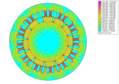
And a closer look. Notice the few magnetic circuits that do not go where they were going to be useful. It will always happen, we just need to design it so that it is easy for the flux lines to take the route we want them to take.... there will always be a few stragglers. There is a small leakage between magnets here, note the little circuit between the center and right magnet. So look out for paths that encourage leakage from one magnet to the next, or straight back to itself.. eg from sinking the magnets more than 10% into a steel rotor to hold them . 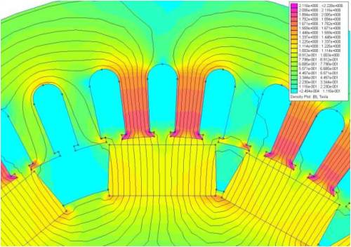
You will see that the flux is concentrated exactly where he wanted it, in the teeth where the coils in question was seated. Every line leaving every magnet is closed somehow. Note the rotor, all those lines joining up the magnets return circuits. If you made the rotor out of aluminium, flux would jump from the front of the magnet straight back to the back, and never see the gap you want it to jump. Thats why you must have steel backing the magnets so the return path is assured. In the axial flux types, we use heavy steel plates at least 8mm thick to achieve the same thing. We use aluminium as a jacket precisely because it does no affect the static magnetic lines and does not encourage leakage of flux from the front to the back, it just mechanically holds the mags in place (dinges used epoxy instead I think). We cannot use Aluminium if the magnetic fields will cut it.. ie in the stator, as we just generate enormous eddy currents. Or any place where alternating or moving fields may cross the al. The best way to do it is to have a steel rotor with mags facing the stator, held in place by some magnetically inert material. Think Magnetic CIRCUITS, and you will do a lot better. Pntrbl, It's all to complex for me thats why I suck up to Dinges and conn him into doing it for me. 
Once you get smart enough to get a good handle on how to use Femm, you will probably know what the model will look like before you start anyway.... but it is nice to see it in living color. Thanks Dinges ........oztules Village idiot...or... just another hack out of his depth |
||||
| Dinges Senior Member Joined: 04/01/2008 Location: AlbaniaPosts: 510 |
I'm still surprized there are so few people building windgennies who actually use this software. I only know of one other person, Sparweb/Steven F. And that despite the fact that FEMM is pretty easy software to learn and use; quite unlike my first FEM package, Nastran... I don't think it should take you more than one or two hours to make such simulations (that is, excluding the drawing of the rotor/stator), and the insight it will give you into magnetic problems is invaluable. The only thing FEMM is not good at is drawing geometries so I normally make those in CAD software and then import the .dxf drawings into FEMM. For very simple geometries drawing in FEMM works, but anything more complicated becomes extremely tedious. You don't need to read and understand the 155-page reference manual to be able to operate the software; this 10-page tutorial is basically all you need in the beginning: http://femm.foster-miller.net/Archives/doc/tutorial-magnetic .pdf The software and more information can be found here: http://femm.foster-miller.net/wiki/HomePage I don't claim to be an expert of FEMM, I don't think I use more than a few % of its capabilities. It should even be possible, using LUA scripting, to simulate cogging and minimize it (I did work on that but didn't get it figured out), make animations ( http://www.anotherpower.com/gallery/album69/Blue_boy_animati e_10ms), etc. If anyone is interested I could make the .FEMM files of the above simulation available, that would give something to play with to learn and explore the software. Just need to find a place I could upload it to. I hope you guys give the software a go, it's pretty easy to learn and is quite a big help in understanding and visualizing these strange magnetic contraptions we build. An undervalued tool, IMHO. Don't believe him, Pntrbl, Oztules is plenty smart enough. I think it's more an issue of being lazy and having other people do the work for him...
BTW, in the past I built my gennies with an aluminium sleeve as inert material; it's only in the very last genny (10 hp conversion) that I used epoxy resin to cast the magnets in. There's little more to add to Oztules' explanation above... but to point the OP to Zubbly's gallery, if he's not yet familiar with it: http://www.anotherpower.com/gallery/zubbly |
||||
| Jarbar Senior Member Joined: 03/02/2008 Location: AustraliaPosts: 225 |
Hello all,I read with interest your contributions.I have been looking at a dual F&P rotor setup for my vawt which is slowly coming to a conclusion.As this thread relates to magnetic fields you can probably help.If I was to place two F&P rotors with magnets facing each other will the combined magnetic force be greater.As it is neccessary to space the rotors apart to allow for both the stators to fit in this configuration.Could I machine down a third rotor and use this with the magnets as the spacer.All the magnets will align naturally.Thus have the extra magnetic force I presume from the spacer contributing to the actual working rotors magnets at each end.And might this be an advantage to its efficency. Anthony. "Creativity is detirmined by the way you hold your tounge".My Father "Your generation will have to correct the problems made by mine".My Grandfather. |
||||
| Dinges Senior Member Joined: 04/01/2008 Location: AlbaniaPosts: 510 |
Anthony, I don't understand your question but I'm not very familiar with F&Ps. It is wisest to start a new thread of yourself and ask the question there, including a drawing/sketch/photo of your (proposed) setup. A picture is generally worth a thousand words. |
||||
| CraziestOzzy Senior Member Joined: 11/07/2008 Location: AustraliaPosts: 152 |
Well, Dinges is right...just read the previous replies after I had downloaded FEMM and learned a new interface to confirm and disprove some wild theories I had about magnetism...I had to use a freeware CAD type program to create the geometries and import them into FEMM. I did confirm that a magnet placed next to a stator tooth with an air gap of 0.5mm redirected the flux through the tooth as I had previously thought after Dinges corrected me on some false assumptions I had when he showed me some FEMM analysis of my previous ideas... 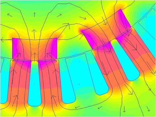
The rotor is solid aluminium as I was advised to make it simple so my mate in Brisbane won't have a dummy spit with something complex. The whole rotor/stator combination is working in theory and looks just dandy... 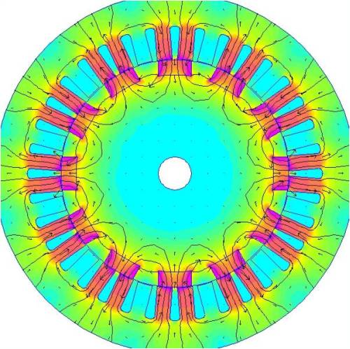
Next task for me is to experiment with smaller N40 magnets so I can cover every stator tooth with a magnet or something similar anyway. Big thanks to Dinges again for re mentioning the FEMM prog...makes life so much easier http://cr4.globalspec.com/member?u=25757 http://www.instructables.com/member/OzzyRoo/ |
||||
| Dinges Senior Member Joined: 04/01/2008 Location: AlbaniaPosts: 510 |
Good to see you got it working ! Nothing like playing around a bit in software to try out the latest crazy idea that gets in your mind. Won't even have to get your hands dirty.
One thing though, the aluminium rotor isn't a good idea. It may work, sort of, but a steel rotor will make much better use of your magnets. I'd try to run two simulations, one with an aluminium rotor (as you've done above) and one with a steel rotor, and then compare the flux-densities you get in the stator. It's my expectation they'll be quite a bit higher using the steel rotor. Would be nice if you could upload the results to this thread. Very nice. I see one thing wrong though in this simulation, an error I made in the beginning too: you haven't defined a boundary condition around your stator ('zero' boundary condition). This causes some of the magnetic fieldlines to leave your stator which in reality doesn't happen. So, define a 'zero' boundary condition and assign it to the outer circumference of the stator. Then run the simulation again. All magnetic fieldlines should then stay within the stator. This may not necessarily be a good idea. I normally strive for 2/3 of the circumference of the rotor covered in magnets, not 100%. Have a look at these pdf files written by the master, Zubbly himself: http://www.otherpower.com/images/scimages/4/z_conversion_all .pdf http://www.otherpower.com/images/scimages/4/zubbly2.pdf As far as 'stator coverage by magnets' goes, your current setup looks actually pretty good to me. It's a 12-pole rotor too and that should make for easy rewinding in a 36-slot stator. In the current situation your magnetic poles will fit exactly within a stator coil, which is the ideal situation that Zubbly describes in one of those pdf-files. I'm talking especially about this image from Zubbly in his pdf files: 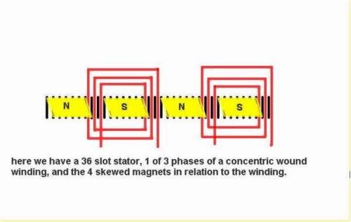
If you 'cover' the circumference of the rotor for 2/3 with magnets you'll nearly automatically arrive at this situation, with a bit of space between the magnetic poles. Each magnetic pole will then (roughly) 'fit' inside a stator coil. If you have a look at Zubbly's photo gallery (http://www.anotherpower.com/gallery/zubbly) you'll see that in most of his conversions the magnetic poles cover about 2/3 of the circumference of the rotor, with a space of about 1/3 between the poles. Only thing you'd still have to take care of is the decogging. Apart from that it actually looks 'fine' as is to me. |
||||
| oztules Guru Joined: 26/07/2007 Location: AustraliaPosts: 1686 |
Yes, CraziestOzzy, Whilst aluminium will work, it will be a poor performer compared to the same magnets on a steel rotor. If you have a look at your strongest fields, they are concentrated in your magnet. If you look at Dinges, his strongest flux is inside the stator teeth where you need it. So you have wasted some of your flux. It is worse than it looks. When you do your calculations for turn/s volt it will be lower than the steel version, and you will have to cram in more turns than you would if you had used steel. This will impair your performance as the new resistance decreases the power of the stator as a square function. If your man wants to cut steel laminate plates rather than machine a solid steel rotor, then this will be a lot better than aluminium I should think. Your magnet managed densities of 1.7 and the stator mostly ended up at 1.2 to 1.3 Dinges magnet started out at .8 or .9 at the magnet, and managed to get the density up to 1.5 in the stator where you need it. That means he seems to have doubled his flux where he needed it from his source, you have managed to tie up most of the flux inside the magnet, rather than the stator. The amount of lines in the magnet itself makes me feel that there is something wrong with this. There seems to be too much flux to go around... like you have n50's in there or something. There is no leakage shown, and this is highly improbable. I would expect leakage to the next tooth as there is no circuit between magnets, and the tooth is midway... it should have attracted some lines. something feels wrong, but I've been wrong before ..........oztules Village idiot...or... just another hack out of his depth |
||||
| CraziestOzzy Senior Member Joined: 11/07/2008 Location: AustraliaPosts: 152 |
Well, thanks Oztules...food for thought and point taken. As some concern is expressed about cogging, I mentioned before I will be having offset stator teeth. As requested, the next picture shows the difference between using an aluminium rotor and an iron rotor to house the magnets. I am going for an iron one
...there was heaps of loss and some hysteric mayhem occurring within the aluminium rotor that was relatively non-existent within the iron rotor. There are heaps of smaller arrows imitating a lump of spaghetti that can't be seen here due to downsizing for the web. It was not looking good for the lighter weighing aluminium. The arrows show where the loss occurred within the aluminium rotor: 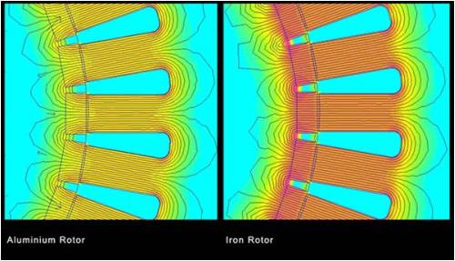
The next picture shows the flux densities compared with change in magnet size and pole count. I liked the even distribution of flux using the 36 pole setup with the smaller magnets. Each magnet had its own stator tooth. The downside here is that the close proximity of the magnets (<5mm) retained most of the flux in the rotor and did not "send" it to the stator. I also liked the 12 pole setup where the magnetic flux was substantially increased using larger magnets with the downside of having 12 stator teeth "dead" with only 24 teeth doing something useful. I will be reducing the outer diameter of the rotor to about 10% of the height of the magnets to see if I can direct flux to where it is wanted...into the stator. Irregularities in flux distribution is due to my design on the FEMM program, something I will work on later. 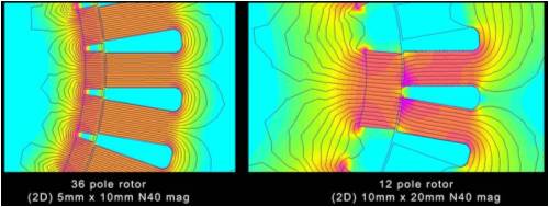
So I think I am settling for the larger magnets of a 12 pole rotor working its magik on a 36 slot stator. It is easier to machine on a 3 axis mill and easier to wire and also using a multi rotor setup, lighter to send in the mail for individual packages. I will have to raise the magnets so that they are not seated 100% into the metal rotor...way too much loss at 100%. You are right Oztules when you said to avoid magnets at close proximity to each other and seat the mags ~10% into the metal rotor. Looking forward to checking these points out inside FEMM. I am also looking as mentioned, at having several rotors at a thickness of about 60mm each. I am very much aware about resistive losses and will be watching my wire combinations closely. The best part I like about this multi rotor setup, is that I can simply add more rotors to the shaft when finances allow for expansion. I obviously will have additional stator laminations to cover the expansion. Once I have my complete design together, I will run it by you gurus first before I send the CAD file to the mill shop in Brisbane. Cheers and thanks heaps for valuable input...I have come a long way and learned heaps since I posted my initial crazy idea.
http://cr4.globalspec.com/member?u=25757 http://www.instructables.com/member/OzzyRoo/ |
||||
| oztules Guru Joined: 26/07/2007 Location: AustraliaPosts: 1686 |
Cool, 12 poles 36 slots is the way to go. Iron core, and if you follow Dinges rotor design (except yours will be geometric 12 sided with skewed stator), with the small ridges to separate the magnets, you will do well. Adding to the design sounds like a lot of work. Each time you will have to carve new blades, and rewire the stator to reflect the new power curve of the alternator... 
I think the hysteric and eddy losses for the Al rotor reflect the logjam of fieldlines under the magnets which are unstable, and will probably switch the lines in the inner center from one side to the other at the slightest tooth ripple.... changing fields through the AL and generating currents. An animation with higher resolution may show this to be the case... or I'm full of it. It may help to get a better idea of your Femms by getting the slot geometry closer to realistic. Your slots can't be shaped like that surely. ......oztules Village idiot...or... just another hack out of his depth |
||||
| Dinges Senior Member Joined: 04/01/2008 Location: AlbaniaPosts: 510 |
Craziest, Good to see you've seen the light.
One more thing, something I neglected earlier to say to Oztules in this thread but which I'll mention now: be careful when you compare two different simulations to eachother just based on the colours. Standard, FEMM assigns other colours to the *same* flux density in different simulations. 'Autoscaling' it's called. This can bite you if you don't realize it. That's why I always include the colour legend in my simulations. You can also force FEMM to always use the same colours for simulations by specifying the lower and upper scale limits. Just a heads-up. The irregularities may be artifacts caused by FEMM. Judging by the output you're using automeshing to generate the grid. I normally don't use 'automesh' but determine the mesh-size myself. I also normally generate pretty fine meshes. This makes the simulation take a bit longer to calculate and show the results but I prefer the more detailed results. I agree with Oztules, I'd build the rotor just once, rewind just once and get it over with. After your first genny you probably have a desire to build a few more (if you're like the rest of us ) which still gives you plenty of opportunity to experiment. I so far haven't heard of anyone who could stop after his first genny. It's habit-forming...
|
||||
| The Back Shed's forum code is written, and hosted, in Australia. | © JAQ Software 2026 |
