
|
|
Forum Index : Windmills : piclog question
| Author | Message | ||||
Gill Senior Member Joined: 11/11/2006 Location: AustraliaPosts: 669 |
I think perhaps the easiest place to make an error is in the making of the serial connections. The diagrams showing front or back of the plugs and socket connections can easily be misunderstood. I know because I've done it myself. With the cable connected, I'd do a continuity check between the plug into the PC and the board tracks. I seem to recall there is a test at the board to give an indication if the input signal is getting through. Off the top of my head, I think a voltage reading on the input of the board whilst running Programming Editor download should be a good indicator. Rather than make another board why not post just the board to me for a check? I have spare 08Ms, cables and power supplies so no dramas there. It'd be posted back in 24 hours or less. Gill (as per profile) PO Box 27 Aloomba 4871 Qld. Just another option. Sure it's always more satisfying if you can trouble shoot and repair it yourself, but if you get stuck??? was working fine... til the smoke got out. Cheers Gill _Cairns, FNQ |
||||
martinjsto Senior Member Joined: 09/10/2007 Location: AustraliaPosts: 149 |
thanks gill, i sent it today, via express post. I would of liked to sort out the problem myself but i am at a loss now as to what to check. the only thing i can think of is either a faulty part or i have got the wrong part on the board. although the serial test via the software seem to work fine. i have enclosed a express post satchel for return, it is fully payed for so just drop into the yellow post box for express once you have looked at it. i apreciate your help, probably just a simple thing wrong with it but they can be the most tricky to find. if you find no errors with the board then it must be in the serial cable i have made, i spent a few hrs last night checking and re soldering the cable and even tried the opposite pins to see if i was miss-interpreting the diagrams. good luck and thanks again martin free power for all McAlinden WA |
||||
| martinjsto Senior Member Joined: 09/10/2007 Location: AustraliaPosts: 149 |
I just finished making a 2nd board, tried to program the chip but received the same error, repeated all the tests above and the results were the same all seem ok. i must be making a mistake with the components or something, has anyone tried the new software we picked up an error in the syntax maybe there is another error causing the issue here, whats your thoughts gill. have you received my first board? it was sent on Wednesday 6th, via express. so should be there soon. thanks again martin free power for all McAlinden WA |
||||
| Gill Senior Member Joined: 11/11/2006 Location: AustraliaPosts: 669 |
Martin, I've checked the post every day and nothing yet. It's not the software provided the syntax check doesn't come up as in error when downloading it to the picaxe. Even if the code is wrong it will still download and yours does not. So the most likely faults are; incorrect circuit either on-board or in the cable, wrong voltage to the picaxe(4.5v to 5v), wrong com port settings, or failed component/s. Possibly faulty components could be ruled out as you still get no download to the second board however the other possible causes are common to both attempts. As I've said earlier, the homemade download cable would be my guess as most probable cause of the fault. When you get the PC talking to the picaxe we could simulate readings of the various inputs to check the picaxe uploading to the computer if problems were found to be there but we need to put the horse before the cart and get the picaxe programmable first.  was working fine... til the smoke got out. Cheers Gill _Cairns, FNQ |
||||
| martinjsto Senior Member Joined: 09/10/2007 Location: AustraliaPosts: 149 |
hi all, still no luck with my logger, i picked up 2 more chips the other day from my suppler, worldwide electronics, and 2 from altronics. tried them all but non worked. i took the board and chips down to worldwide electronics. Mike tried to program the chips using a commercial programing device that fitted most types of chip sets and some good commercial software. when he tried to program the 08m it would error out at line 2007, this was strange as the program does not get near that point. we tried other chips and received similar error. mike then using his software adjusted some setting that was by default incorrect and, after erasing the chip first, it worked and verified the download. i am not sure what the default setting was but he changed it to LP oscilloscope. which stands for low power. that's the good news i guess but alas once i got home and plugged it into my board, ran the logging software and didnt get any data at all just zero's in the calibrate tab. Gill i dropped into the Aussie post to see where the parcell is but i couldnt find the tracking number sticker (might of left it on the envelope) 
so i couldnt track it, they said it should of got there by now after 6 days via express post? and gave me a complaint form lol i tossed it into the bin. ah well, might have to try gordons one, Gordon, could you pls post on here or email me the parts list and if you have it the circuit diagram i would appreciate it and also give me more experience with these circuit to maybe better understand the picaxe intricacies. i will keep the board for future assessing might figure it out one day. my email address is martinjs@iinet.net.au thanks all for your support martin free power for all McAlinden WA |
||||
| Gizmo Admin Group Joined: 05/06/2004 Location: AustraliaPosts: 5182 |
This is all a little weird. This worries me... Thats not right, its possible he's wiped your chips. The picaxe ONLY uses the programming editor available from the picaxe web site. If he's tried to use a generic microchip programmer then I'm afraid he's not familiar with the picaxe chips and may have fried your's. See the PicAxe chips come with a boot loader to let it comunicate with the PC via a serial cable, and he may have wiped that. Have you checked out this page.... http://www.thebackshed.com/Windmill/articles/PicAxe.asp Its the basics, just to point you in the right direction. I would suggest you grab a new chip, ( lucky they are cheap ) and connect it as shown further down that page. Add a LED and 560r resistor in series to output 1 ( pin 6 ), run the program shown using your programming editor, and if all is right, the led will start flashing. You need that eureka moment, like learning to ride a bike, suddenly its just all makes sense. Sorry its been such a rough ride so far. Glenn The best time to plant a tree was twenty years ago, the second best time is right now. JAQ |
||||
| martinjsto Senior Member Joined: 09/10/2007 Location: AustraliaPosts: 149 |
yes your correct i do need a eureka moment im starting to think its not worth the effort but i am a stubborn bugger, just have times of frustration. i have made that circuit, tried it with a new chip and got the same hardware error 
im not too sure what Mike did, he is a very educated man form UK who seems to know what he is on about, not that i understand much of it. but he did get it programed, i just cant seem to use it on my setup, i will try to find out what software he used and what he did, i read on the UK forum about serial port issues, older computers seem to be a lot better than newer ones when using the serial, not the USB. i probably have a combination of hardware, parts or circuit errors throw a serial issue in too and im going around in circles. i will try the LED circuit again and ensure it is exactly as the page shows, maby just getting the little LED to flash will be enough for the rest to fall into place thanks Glen martin free power for all McAlinden WA |
||||
| Gill Senior Member Joined: 11/11/2006 Location: AustraliaPosts: 669 |
Martin, Package arrived today (Tuesday). And they call that EXPRESS. ha ha ha . 1 0pto in back-to-front, PicAXE chip not working. I too am quering if PIC or PicAXE was fitted? Still some problem with communication via serial cable. Working on it tonight and tomorrow if no joy. Will advise tomorrow. 
was working fine... til the smoke got out. Cheers Gill _Cairns, FNQ |
||||
| Gizmo Admin Group Joined: 05/06/2004 Location: AustraliaPosts: 5182 |
Hi Martin. Good to see your keeping at it, thats how we get places. The fact you still get a hardware error with that simple circuit means there could be a problem with the serial port on your PC, either driver or hardware related. Even without a LED fitted, you should be able to upload the program into the PicAxe and not get an error. Do you have another PC you can try? Serial comunications can be a real pain sometimes. Last weekend I spent 2 hours trying to get an old Burgy cnc oxy cutter to talk with a Vista PC via a 3 wire serial, there are a lot of combinations to go through! At least the PicAxe system uses set port settings, you just need to find the right port. I'll download the latest version of the PicAxe editor tomorrow so I'm using the same version as you, there may be a few quirks I'm not aware of. Will get back to you. Glenn The best time to plant a tree was twenty years ago, the second best time is right now. JAQ |
||||
| martinjsto Senior Member Joined: 09/10/2007 Location: AustraliaPosts: 149 |
thanks guys i didnt realise opto had a set way around, cheers gill thanks for the effort. im nearly finished the new test board for the LED, i will post results as they appear yes Glen i have 4 different pcs to choose from, from a up to date gaming system to a old gateway 9100 laptop. the chips are from two different suppliers one being altronics, i wouldn't think they would give me the wrong chip but you never know. ah well back to it, i WILL get this working, might help if my brain worked better 
martin free power for all McAlinden WA |
||||
| martinjsto Senior Member Joined: 09/10/2007 Location: AustraliaPosts: 149 |
ok tested the LED setup, syntax checked ok rebooted computer and tried the software. no joy
must have a serial issue or wrong chips or cooked chips. i will pick up some more, mention the fact about the 08m and the unique programmer software and see what happens, i will also try different serial configs see if i can fluke it. martin 
free power for all McAlinden WA |
||||
| martinjsto Senior Member Joined: 09/10/2007 Location: AustraliaPosts: 149 |
something i just found... this site http://www.hippy.freeserve.co.uk/picaxepo.htm shows two types of 08m chips one with differently labled in and outputs to the other mine is the 12f683 do it make any difference? martin free power for all McAlinden WA |
||||
| Gill Senior Member Joined: 11/11/2006 Location: AustraliaPosts: 669 |
Martin, Before you said you were getting this error message 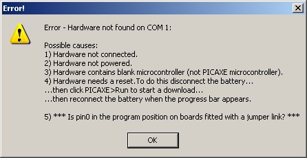
Or has it changed to this one which is what I'm getting now and I can't track it down? My chip is perfect in a different board. 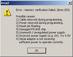
If your having same error I'm looking for the common component at fault. was working fine... til the smoke got out. Cheers Gill _Cairns, FNQ |
||||
| GWatPE Senior Member Joined: 01/09/2006 Location: AustraliaPosts: 2127 |
Hi Gill, I have had problems with USB-SER adapters. The PCMCIA type work well on a laptop as do onboard SER on a PC. I use a 3pinheader for the SER connection. A lot simpler to make a cable adapter than make PCB for DB9. I use an LED wired in a plug that connects accross the serout and ground. this tests at a glance, any picaxe program that uses serout. Any program can have a line added to test operation, that can then be removed later. I have never lost a picaxe chip, even reverse connection of power. I am up to close to 50 Axe-08M in service so far. There must be a cct voltage problem or serial connection. Programming uses more chip power and errors will occur if voltage drops during this operation. Gordon. become more energy aware |
||||
| martinjsto Senior Member Joined: 09/10/2007 Location: AustraliaPosts: 149 |
the first error is the main one i get, i did get the 2nd one once, when i connected to my sons computer, I could see firmware ok, then i got the 2nd error then i tried to program the chip and got the 1st error. even with the LED test which removes most components i get the 1st error, i checked LED polarity and the resistors b4 assembly. i have battery packs of 4.5 to 5.5 v and a power pack for 4.5vdc which i use for the tests, still same error i will pick up some more chips today and try again. i have set up a 3 pin cable as well gordon, using this web site as a guide http://www.hippy.freeserve.co.uk/picaxeio.htm#The_Download_I nterface hopefully gill will find an error on the board or with the chip else it must be the serial on the computer my dad always said "when at first you dont succeed, try, try again" i didnt realise there could be another 50 or so tries it there lol
martin free power for all McAlinden WA |
||||
| Gill Senior Member Joined: 11/11/2006 Location: AustraliaPosts: 669 |
Gordon, I seem to have it licked now. As you say, serial or power was what I concluded too. The official Picaxe Forum has many queries on this error and none of the experts can present a sound knowledge of its cause. One of those where every man has a different opinion from varying approaches. However a reoccurring theme was bad power not so much low power. Another was change computer and change cable ( Serial to USB (not adaptor)). Sounded a lot like recommending assassination by stabbing someone with a blindfold on. Now I had previously bypassed the reg with 4.7v direct battery supply but because I want to be an expert too one day, I tried them all, and like them I now have 'MY Opinion'. I changed Glenn's circuit by adding 0.1uf caps to either side of the voltage reg like the recommended picaxe power supply. I used a different computer, and used a USB adaptor lead. And it worked. Download OK, Upload OK. Great! Back to the original computer with original serial cable and all still OK. Go figure. 'MY Opinion' is that I don't know what happened and I'm still a long way from expert status. Ah well, it's still a successful outcome. Martin, Have sent off your board within 24 hours as promised. When you get it back please connect up the power and serial cable and then open Programming Editor. From the toolbar, select PICAXE, then Terminal. You should immediately see the incoming data stream. IF NOT, the problem is in your serial cable or computer settings. Initial connection: 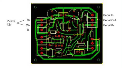
Of minor concern but major effect is where you connect the 12 Volt power to the terminal strip. B+ is clear as it's the top one. The middle one is W- (Windmill neg ?) and the bottom one is B - (Battery neg ?). For setup and testing connect 12 volts across the terminals you have marked B+ and W-. Your terminal B- is for your Amperage metering and is not used for powering up the Picaxe. Glenn, In the site code and also in the .zip download of Version 1. Logger Regulator, this line needs editing: sertxd("[<V>", #volt, "</V><I>", #Amp, "</I><R>", #RPM, "</R><M>", Mode, "<M>]") It needs a # in front of Mode, and a / in "<M>]" You might like to work your magic keyboard on them when you, got a minute. 
was working fine... til the smoke got out. Cheers Gill _Cairns, FNQ |
||||
| martinjsto Senior Member Joined: 09/10/2007 Location: AustraliaPosts: 149 |
excellent work gill, thanks a million i will do as you have stated to my other board tonight. should i edit the line mentioned above? or wait for glen to modify and download the new .zip version i wasn't too sure about the neg connection to my B-, i actually tried it on the new board with the battery neg connected to the w- but i have other errors to sort out b4 it will make a difference. thanks again and i hope you didnt loose too much time on it. martin free power for all McAlinden WA |
||||
| martinjsto Senior Member Joined: 09/10/2007 Location: AustraliaPosts: 149 |
wowa yeehaaaa it worked!!!!
well done gill glen and gordon many thanks, the board was fine i just added the caps and re-made a new serial cable, also found an incorrect resistor on the power circuit part of the board whist i was soldering on the caps. you should of seen my face when it finally starter downloading  , i scared the SH$% out of my wife karen, by my yells of excitement after i saw the download successful lolol. , i scared the SH$% out of my wife karen, by my yells of excitement after i saw the download successful lolol.
this must be a laugh to you guys but a lot learned here now im off in the world of picaxe never to be seen again by my wife and kids lolol sorry about my over enthusiasm but....... EUREKA
martin free power for all McAlinden WA |
||||
| Gizmo Admin Group Joined: 05/06/2004 Location: AustraliaPosts: 5182 |
Well done Martin, I knew you would get there. Glenn The best time to plant a tree was twenty years ago, the second best time is right now. JAQ |
||||
| martinjsto Senior Member Joined: 09/10/2007 Location: AustraliaPosts: 149 |
hi guys, sorry to persist with questions on this project. I went down to my block on the weekend and set up logger, i got volts and amps input and watts and watt hours displayed one thing i didn't get is the RPM as i didn't have the A/C connected at this time and the wind speed, the wind speed should of worked as i had it connected to a anemometer i made using a computer fan and a reed switch, i had one wire from the anemometer connected to the bat+ the other to the top input to the opto. i tried earthing the bottom input as shown on the c/diagrammed still no data, i checked the voltage across the input to earth and got on/ off of power, twice per revolution of the anemometer as i would expect from a two magnet anemometer. my question is whether i should change the 10k resistor on the top pin to the opto to a 39k like the power circuit does to the 22k as i am using this for a 24v setup, if so i may of cooked the opto, dont panic Gill lol this is on my 2nd board i made for 24v not the one you fixed for me 
also whether i should change any other resistors for the 24v board, the block picture in the circuit diagram folder only shows the 22k for the voltage part of the circuit and doesn't suggest any other being changed. cheers martin ps i had the jumper pin on wind speed not dump free power for all McAlinden WA |
||||
| The Back Shed's forum code is written, and hosted, in Australia. | © JAQ Software 2026 |
