
|
|
Forum Index : Windmills : Making blades with a ChainSaw
| Author | Message | ||||
| Dinges Senior Member Joined: 04/01/2008 Location: AlbaniaPosts: 510 |
Good results so far, Oztules. Looks like you're on to a winner. Do I see a next, even bigger, axial flux in the near future ? Would be a waste to have all those nice large neos sitting in a box in the attic... 
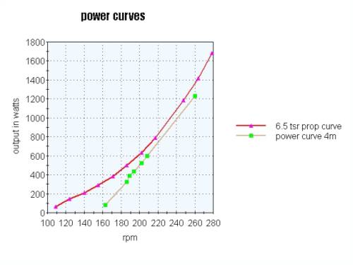
Interesting graph, your blades seem to be a pretty good fit to the generator. I assume the red curve is a theoretical construct (with the vertical scale being very dependant on efficiency of the blades; which value did you assume ?) and the green curve of the generator is actually measured. Over the useful range of the genny the curves match pretty well. In the lower range you have excess turbine power, this should help in start-up and prevent stall. I've made a spreadsheet to calculate similar data for my 500W conversion, but I've not put the results in a curve; must do that soon. Already have the measured curve for the generator itself. As far as TSR goes; are those unloaded or loaded TSRs ? Strange those batteries (I estimate them at 100-150 Ah ?) can't take the 20A charge for any reasonable amount of time. I've pushed 10A into a 7Ah battery without voltage rising much above 16V. I hope those crocodile-wires are MUCH beefier than the ones I have (and that look exactly the same as yours, and probably came out of the same factory in China). I consider them 'clippable fuses'. The fan on the yellow motor and the wires running from that motor to the axial flux indicate to me you're working on some overunity scheme... Cunning. |
||||
oztules Guru Joined: 26/07/2007 Location: AustraliaPosts: 1686 |
Dwyer, The round thing is simply a 3ph rectifier. 3 stud diodes on each half circle common cathode on one side, common anode on the other. A 6mm gap separates them + from - . It is good for 60A, and stays cool at 1kw without any problems The coils are low resistance. They each weigh a pound almost exactly (actually .459 kg (1pound=.453g) So for 1.8mm (13gauge) wire, there are 63.8feet/pound.. so I have about 64 feet of wire. The wire is 2.042 ohms per 1000feet of wire. Each phase group has three coils, each star phase has 6 coils. So in Delta, it is 64x3=192 feet of wire And in Star it is 64x6=384 feet of wire If 1000 feet has 2.042 ohms resistance, Then 192/1000 x 2.042= delta = .392 ohms and 384/1000 x 2.042= star = .784 ohms I tried hard to get the resistance down to a respectable level (as is my want), and I think I have achieved that. The voltage did not sag under the increased load of the batteries as the power went up. The stator stayed very cool at 1kw levels. ..........oztules Village idiot...or... just another hack out of his depth |
||||
| oztules Guru Joined: 26/07/2007 Location: AustraliaPosts: 1686 |
Hmmm Dinges, Do you remember how I felt the alternator should be designed... resistance resistance etc.. It seems to be paying off at last. This is more towards Flux's ideals rather than the Danb's. I believe that the Dans wire theirs too higher resistance, and thats why they seem to sail close to the wind with regards to hot stators. With the same no of the same size magnets,Danb's blurb on their heavy duty stator goes like this: "This stator is wound with #15 gage wire. It has 9 coils and each coil has 105 turns in it. " (mine has 100turns #13) "After you rectify the output to direct current, this stator should produce 48 Volts at 140 rpm. The blades should be 10 foot in diameter." (Mine cuts in around the 120-125rpm and uses 13 footers) "In our tests we believe this stator will be about 50% efficient at 1000 Watts. Sustained output above about 1000 Watts may overheat this stator so you should design your machine to furl before that point." (mine barely feels warm to the touch after 5mins above 1000-1500watts) So once again Flux is correct. The only real difference is that mine is a thicker stator (yes thicker by 3mm), and the plates are 2" bigger, and only my mags are n45 not n40...no big difference there. So by skimping on the rotor size, they have ruined the leakage flux and coil space and gotten an inferior result by almost half. There is a lot to be said for chasing low resistance. All the effort that goes into that solves a lot of other compromises along the way. 2 extra inches of steel plate would have made a huge benefit for so little cost. As it is, by their standards, this could be used on a larger prop... more power at lower wind speeds. They seem to be after low wind speed production (a good thing), but by stall rather than larger blades and earlier furl. The tail is light on this one, and seems to start to furl at 1.3-1.5kw. Haven't had any strong winds since it has been up ... all less than 30kph according to the weather people. I used a prop efficiency of .3 tsr 6.5 lift co-efficient .8 and attack angle of 4degrees. "The red curve is a theoretical construct" .. yep. The green is measured. As far as TSR goes; are those unloaded or loaded TSRs ....loaded. Unloaded is roughly twice. The batteries were too soft for the true graph to appear. I don't believe the lower figures to be anything like that if the battery were low volts (41v instead of 56). They were basically fully charged anyway, and only took serious current for a short time, then the voltage went up, which the TSR loved, and powered away. The low end will be totally different for low batts. I assume I will need a resistor in normal use, or a long line. Because the 700 cranking amp batteries didn't load it properly, I won't know just how it performs. I suspect it will need a larger blade to make it happy, and the match is not as good as it currently looks... but I live in hope. Will lower the batt volts and see what happens. A larger bladed version is on the drawing boards. However, I can claim the high ground at the moment, as I have the figures on the board.... even if a little skewed.. Interesting... you spied my overunity experiment too. It gets 1 gazillion parsecs to the dwarf star... and stops the trailer blowing away too.... multi tasking?? .......oztules Village idiot...or... just another hack out of his depth |
||||
| GWatPE Senior Member Joined: 01/09/2006 Location: AustraliaPosts: 2127 |
Hi oztules, This comment may be a bit off topic and should probably be discussed further on a new thread, possibly wire resistance and axial flux? That is an amazing amount of copper wire. I have just calculated that my machine, at 455W capacity, has a measured 170g of copper, 11 coils per phase and 4 phases and 4g copper per coil. Each gram of copper wire produces about 3W at full output. Each phase of 11 coils has a resistance of 0.8ohms. Maximum loaded current per phase is 4.2A, with the average maximum loaded at 4A. I rate the stator on my mill as electrically stiff. Your machine has approx 4000g of wire for 1500W. This equates to 0.38W per gram of wire. I suspect that this would be similar for DanB and Flux type designs. My machine has independent rectification, so the effective resistance is 0.2ohms for 455W at 24V. If your machine had independent rectification per phase, then the effective total resistance would be 0.13ohms. This would be for 1500W. That low resistance at 48V is a great result. cheers, Gordon. become more energy aware |
||||
| dwyer Guru Joined: 19/09/2005 Location: AustraliaPosts: 575 |
hi Oztules thank for your replied as l think you are most clever aussie feller reason l did had alook on webs for months for some information how to rewiring on my 160 amp low rpm truck alterantor still can't find it until l saw your clever know how to rewire on correct size copper, got the correct ohm's law and your windmill  WOW l do love your great ideas and your talest same to Dinges other smart guy know what he is talking about Flux and his design 3ph motor so both you should recive Gold Metal from Beijing Olympic games WOW l do love your great ideas and your talest same to Dinges other smart guy know what he is talking about Flux and his design 3ph motor so both you should recive Gold Metal from Beijing Olympic games
Dwyer the bushman |
||||
| oztules Guru Joined: 26/07/2007 Location: AustraliaPosts: 1686 |
Thanks for the kind words Dwyer, But I think you will find I just rabbit on more than the others. There are many many very well informed people here, you just have to ask your questions, and they will be answered by someone.... (I just seem to gabble on more than most.) 1 more thing on the star delta stuff, although the resistance of delta is half that of star, when in operation, the "effective" resistance of Delta is 1/3 of star. More info on that here Your welcome and glad to have helped if I have. .....oztules  Village idiot...or... just another hack out of his depth |
||||
| oztules Guru Joined: 26/07/2007 Location: AustraliaPosts: 1686 |
Gordon, I agree that another thread devoted to resistance will probably do more good than harm. Look forward to it. ........oztules Village idiot...or... just another hack out of his depth |
||||
| GWatPE Senior Member Joined: 01/09/2006 Location: AustraliaPosts: 2127 |
Hi oztules, I remember that axial flux machines as described elsewhere have been rated at 50% efficiency at max power. I had doubted this. I calculate that your machine would have an expected efficiency at 1500W into a 48V battery of approx 90%. This would account for the minimal heating of the stator after 5 mins. I would expect that the stator on your machine could dissipate approx 200W. The current would amount to approx 40A, so the expected power output could be close to 2000W. Obviously you could do a static test of all windings in series with increasing currents to test the max power handling capacity, no need to fly the mill this way. Good luck with the chainsaw with the bigger blades. Will you need a bigger tree? cheers, Gordon. become more energy aware |
||||
| Dinges Senior Member Joined: 04/01/2008 Location: AlbaniaPosts: 510 |
90% efficiency would seem too good to be true to me. Can you explain how you arrived at this figure ? Anyway, I did some quick & dirty math comparing Oztules' efficiency to that of the Dans: Oztules used #13 wires (Argh, hate those AWGs) i.e. diameter 1.83 mm, whereas the Dans use #15, 1.45 mm. This means Oztules has 1.83^2/1.45^2 = 1.6 times as much copper area, or about 38% less resistance simply from using thicker wire. Since he uses 100 turns vs. the Dans 105 turns, he uses less length of wire (assuming identical coil geometry, which maybe wrong, as Oz has increased the rotor diameter with 2" and so now uses larger diameter coils than the Dans), so his resistance would theoretically (if identical coil geometry as Dans) be another 100/105=~ 5% lower. (more likely his resistance from this would actually be more, not less, than the Dans). So combining the -37.5% and -5% lower resistance, we get about -42% less resistance. More likely it'll be a little less, perhaps 'just' 35-40% less resistance than the Dans. However, as P=I^2*R, 40% less resistance means 40% less power lost as heat in the stator. That means Oztules can nearly double his useful output power (actually, more a factor 1.67 in this case)before his stator heats up as much as the Dans... Now, if he managed to reduce his restance a little bit more to only 50% of that of the Dans, his rated output power would actually be double (for a same given heatloss absorbed by the stator). That'd be an interesting test. Another interesting measurement would be using a Prony brake to determine efficiency. I'll try to run such a test ASAP on my 500W motorconversion. |
||||
| oztules Guru Joined: 26/07/2007 Location: AustraliaPosts: 1686 |
Thanks for that Dinges, I figured it to be about half..... due to the nature of the load, the voltage will rise a bit as the current rises, so output power will go up it bit more than you think without increasing the current at the rate you thought..... ... did I mention resistance before?? it makes the driver a lower impedance which pays dividends, by pushing the voltage higher than would otherwise be.  Certainly frightened the life out of those big batteries I used for the tests. At one stage it pushed them up to near 75v... and they are near new... Certainly frightened the life out of those big batteries I used for the tests. At one stage it pushed them up to near 75v... and they are near new...
I will be furling at 1.2-1.5kw, so I expect a good life from the stator Look forward to the tests. ..........oztules Village idiot...or... just another hack out of his depth |
||||
| GWatPE Senior Member Joined: 01/09/2006 Location: AustraliaPosts: 2127 |
Hi dinges, The efficiency is calculated this way. For 50% efficiency, half of the shaft power is dissipated in the load and half in the stator. I doubt that oztules had 1000-1500W being dissipated in the stator on his machine. the efficiency is related to the resistance. An axial flux machine has only i^2R and eddy current losses in the copper. The eddy currents are related to the insulated wire gauge of the copper in the rotating field. The i^2R is obvious. A DC static curent test is useful to check the power dissipation ability of a stator. I checked the stator on my mill at the maximum individual winding current of 4A with all windings placed in series. This technique is to allow a lower current power supply to be used. In my case, I only needed a 5A supply and not a 20A. Perhaps you can estimate and present the expected efficiency of oztules stator by your reckoning. I am not able to comment directly on the eddy current losses in oztules machine. I spent a lot of time with wire testing to settle on the wire configuration in my machine, to reduce eddy current losses to practically 0. The choice of winding shape and placement coupled with the magnetic field shape and strength determines the best use of the copper. My axial flux mill was designed for a solar car use originally, so I optimised for 1500rpm and 120VDC bus. This was a rated 2kW as a motor, continuous maximum power. The design was not perfect as a motor for automotive use because of the poor use of the copper at low rpm and up hills. A dual motor design for low and high speed running would be better. The design is very good for a windmill though. I will say that the higher peak current that present with a battery loaded sine wave output may contribute to lower wire efficiency into a battery load. I have presented a lot of logged data from my windmill relative to wind power and I have seen that my blade, axial flux mill, rectifier, maximiser system places about 30% of the wind energy to the battery terminals. If the stator in my machine was only 50% efficient, then the rotor would have to have 60% capture efficiency. {don't think so} I have also measured near unity power transfer efficiency as a motor generator. I expect to test my F&P machine this weekend. I will be busy for a while with this. cheers, Gordon. become more energy aware |
||||
| Dinges Senior Member Joined: 04/01/2008 Location: AlbaniaPosts: 510 |
Hello Gordon, I was interested in your calculations on I^2*R-losses but I'll show you what I arrived at. For a 3phase machine: P = sqrt(3) * Eline * Iline Let's assume Oz's total input power is 1000W and he uses 50V system voltage: 1000 = 1.73 * 50 * Iline 1000 = 86.5 * I I = 11.5 A (I'm not 100% sure this phase current is correct, maybe someone can confirm) The source impedance of his genny, wired in star, is 0.785 * sqrt(3) = 1.36 ohm So powerloss in the stator P = I^2 * R = 11.5^2 * 1.35 = 180 W. Or determined in another way: power loss per phase is 11.5^2 * .785 = 104 W per phase. In 3-phase configuration the total powerloss would be sqrt(3) times that, i.e. 180 W. So, for 1000W mechanical input power he'd get 1000-180 = 820W electrical power out, so efficiency becomes eff = inputpower/outputpower = 820/1000 = 82% I consider 82% efficiency to be very good, and a more realistic value than 90% (which I'd find *extremely* good...almost too good to be true). The above doesn't take into account eddy current losses. I don't know how to measure these losses apart from using a De Prony brake to determine the actual mechanical input power. |
||||
| oztules Guru Joined: 26/07/2007 Location: AustraliaPosts: 1686 |
In practical terms, it will be somewhere nearer 85%. In practice these power levels will build up fairly slowly. (weather conditions). By the time I will be getting the full continuous 1kw, the battery voltage will be around 54-60v for a normal battery pack being charged at 20 amps (400ah or so) or there abouts. (these poor batteries went far and away above this.. as high as 78 I think) So when calculating I would assume v=55-56v . At lesser charge rates, then lower volts. These figures come from Jamies batt bank (500ah 24kwh), when full production finally gets in town (the wind turns up), you can be sure you don't really need it with these bigger machines, and the batteries will have a fairly high voltage... certainly not below 54v. This brings your (my) loss to about 144w.... 85% or so. Because Delta is 1/3 star impedance... In delta it would be (.785/3*sqrt(3))=.45 x 10.31sq =47 watts loss 1000-47 = 95.3%....feel very afraid. can this be right? .......oztules Village idiot...or... just another hack out of his depth |
||||
| GWatPE Senior Member Joined: 01/09/2006 Location: AustraliaPosts: 2127 |
Hi oztules, I was in the middle of a reply to dinges, so I will can that. I had misread your post and calculated for independent delta and 1000W@50V gives 91%. Recalced in star and the figs end up at 79% into a battery load. I think the 95.3% does not allow for the higher than RMS peak battery currents. Most AC formulae work well with sine waves, but a battery load messes things up. This is in the ball park I measure from my mill. Hi dinges, Sorry about that. My calcs are pretty close to yours with an exception that I allow for increased loss due to higher peak currents with a battery load. The increased efficiency relates to the increased angular velocity of the magnetic field past the coils in delta. cheers, Gordon. become more energy aware |
||||
| Dinges Senior Member Joined: 04/01/2008 Location: AlbaniaPosts: 510 |
Very valid point. All the math in my reply only applies to nice sinuso�d waveshapes and resistive (linear) loads. Which batteries aren't. And there may be quite some total harmonic distortion (THD) in Oztules' genny as well. Then again... If Oztules used an RMS meter to determine charging current, it should have come out with the correct RMS current and so the above math would apply again then ? I'll lay low for a while and leave youse to it, don't want to take over Oztules' thread. |
||||
| oztules Guru Joined: 26/07/2007 Location: AustraliaPosts: 1686 |
Dinges... meter was rms analog. Waveform does not effect the measured rms into the battery. It will only effect efficiency in the alt/rectifier circuit. It does look as if at lower power (1kw) in delta it will be around 90%, and star around 85%. (Gordon, use 55v, it seems to be more realistic) It would explain the near cold stator. 5 mins@ 200w would be quite noticeable I suspect... Remember, like all wind stuff, it is a dynamic system. The battery impedance changes as well (which stuffs up mppt), and radically changes the stator efficiency. As the SOC of the batts goes up, so too does the efficiency of the stator..... which further pushes up the SOC voltage ...which..... and on it goes. Dinges "I'll lay low for a while and leave youse to it,"..... you can run but you can't hide 
.........oztules Village idiot...or... just another hack out of his depth |
||||
| GWatPE Senior Member Joined: 01/09/2006 Location: AustraliaPosts: 2127 |
Hi dinges and oztules, The battery loading problems significantly change the power dissipation in the copper. The best system is pure DC current where the average current and the instantaneous current is the same. The RMS, is the average current and is useful for part of the calculation. The actual time the wires are conducting and the actual current is the only way of calculating the true copper loss. If RMS only is used, then the calculated copper dissipation will be in error and lower. This aspect was missed in another thread on power transmission and batteries and wire sizing. Oztules, you may note on the maximiser thread that the output battery voltage is compensated for with the variable gain system I have used. I used frequency modulated PWM to achieve this. This is a little off topic, so will leave it to chainsaw discussions for now. Gordon. become more energy aware |
||||
| Gizmo Admin Group Joined: 05/06/2004 Location: AustraliaPosts: 5182 |
I've put Oztules chainsaw made blades story up on the main site as a article on the Articles /Readers Windmill page. This sort of information is worth saving, forums tend to loose interesting stuff like this, the details get lost in time. If anyone thinks there are other stories in the forums that should have their own web page, please let me know. Glenn The best time to plant a tree was twenty years ago, the second best time is right now. JAQ |
||||
| KiwiJohn Guru Joined: 01/12/2005 Location: New ZealandPosts: 691 |
Glenn, Mahela's RPM measuring technique on the "how to speed up the motor" topic is surely worthy of recognition somewhere! |
||||
| oztules Guru Joined: 26/07/2007 Location: AustraliaPosts: 1686 |
KiwiJohn, I was just trying to picture myself and the 4m prop in a 20mph wind.... It could get very exciting very quickly. I think a very long piece of string and a pair of emergency scissors would probably do it
She is pretty scary to get near when she's running at that windspeed.  .......oztules ...with too short a string.. .......oztules ...with too short a string.. Village idiot...or... just another hack out of his depth |
||||
| The Back Shed's forum code is written, and hosted, in Australia. | © JAQ Software 2026 |
