
|
|
Forum Index : Microcontroller and PC projects : Which is the latest Micromite driver for Nokia 5110 LCD
| Author | Message | ||||
| phil99 Guru Joined: 11/02/2018 Location: AustraliaPosts: 3321 |
Nokia 5110 phone LCD panel connections - https://serdisplib.sourceforge.net/ser/pcd8544.html Using the connection diagram from the site above have traced the LCD panel and keypad tracks back to the pads that connect the front panel PCB to the motherboard. The pads look like those for a 28 pin SMD IC with a 1mm pitch. Standard ribbon cable is too fat so cut some from an old ATA100 HDD cable. Soldering required a bright light, magnifier and patience. The keypad number section use the same 4 row x 3 column layout and numbers (inc. * and #) as the MMBasic keypad command. The 4 keys in the row above it can be wired as column 4 and use the MMBasic 4 x 4 setup. All that is required is to bridge adjacent pads C4abd and C4c in the diagram below. The LEDs for the screen and the keypad have driver transistors connected to the LED Ctrl pad so can be controlled directly by a PWM pin. 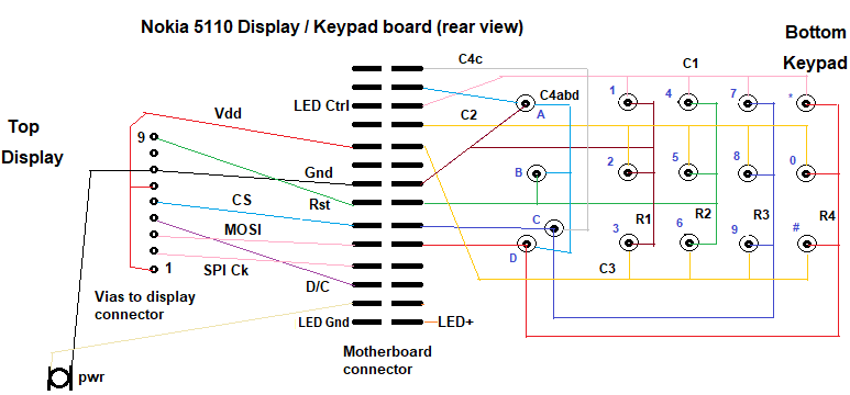 As the power button connects to ground it could be used as a reset button. Edit: Using the MMBasic Keypad command requires 8 pins for 4 x 4 keys. A 74HC595 and some other components can read the keypad with just 2 MCU pins. A DOUT scans the keys via Bitstream and a INTL sub reads the pressed key. ' KeyPad_RP2040_74HC595_2_Pin_v01.bas - Program 4x4 Key Pad ' ' Keypad reader using a 74HC595 and 2 MCU I/O pins. ' For more than 8 rows plus collums daisychain another 74HC595 chip or two. ' then adjust the Rows and Cols limits for the For / Next loops. ' 1 chip is up to 16 Keys, 2 is up to 64 (8 x 8), 3 is up to 144 (12 x 12) ' keypad does not need to be square. 2 chips = 16 outputs so could do 12 x 4 (12 + 4 = 16) ' SetPin 22,dout: Pin(22)=0 : CLS 1 'N5110 LCD backlight Text 9,6,Time$ : Text 2,25,Date$ Dim Integer Rows = 4, Cols = 4, Key = -1, OutPin=MM.Info(pinno GP0), InPin=MM.Info(pinno GP1) SetPin OutPin,dout : Pin(OutPin)=1 'initialize keypad rows HC595 OutPin,Rows+Cols,0 SetPin InPin,intl,KP_int,pullup 'initialize keypad columns Sub KP_Int t=Timer Pause 2 'key de-bounce time, adjust to suit your keypad Local integer R, C For R=0 To Rows-1 hc595 OutPin,Rows+Cols,15-(1<<R) If 1-Pin(InPin) Then Exit For Next hc595 OutPin,Rows+Cols,0 For C=0 To Cols-1 hc595 1,Rows+Cols, (15-(1<<C))<<4 If 1-Pin(InPin) Then Exit For Next hc595 OutPin,Rows+Cols,0 If Rows-R Then Key = R*4+C End Sub Sub HC595 Out.Pin As integer, RC As integer, Dat As integer 'Data output Pin, number of Rows+Cols, Word to output Pin(Out.Pin)=1 'ensure correct polarity for Bitstream Local integer n, el=RC*2-1, B(el) For n=0 To el Step 2 'prepare Bitstream array B(n)=3-(Dat>>(el-n)\2 And 1)*2 'low data pulses, 3uS=0 ,1uS=1 B(n+1)=1 '1uS high spaces Next Device BITSTREAM Out.Pin, el+1, B() 'send it Pin(Out.Pin)=1 : Pause 0.04 ' >20uS high = latch clock End Sub Do ' Text 9,6,Time$ : Text 2,25,Date$ 'for N5110 LCD If Key+1 Then Print "Key";Key, Timer-t;" mS" : Key = -1 Loop End ' 74HC595 connections ' 3V3 to pins 16, 10 ' Gnd to pins 8, 13 ' BitStream input to pin 11 (clock) ' pin 11 - 1k8 - pin 14 (data in) - 1n5 - Gnd ' pin 11 - A-diode-K - pin 14 (ser. data in) eg 1N914 or 1N4148 ' pin 11 - 4k7 - pin 12 (latch) - 1n5 - Gnd ' pin 11 - K-diode-A - pin 14 (latch) ' pin 9 (ser. data out) to next 74HC595 (if used) pin 14 (ser. data in), ' parallel pin 11 to pin 11 and pin 12 to pin 12 ' 4x4 Row output pins:- 15, 1, 2, 3, ' 4x4 Column output pins:- 4, 5, 6, 7 And the circuit diagram. The Bitstream pin goes to the input and the output goes to the INTL pin. Edit 2. There is a slightly updated program and circuit diagram here:- https://www.thebackshed.com/forum/ViewTopic.php?TID=18525&P=2#250889 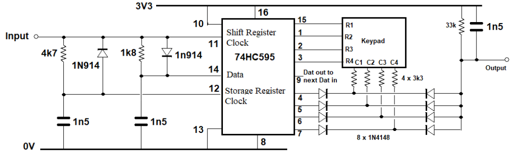 And a MicroMite2 version. ' Keypad reader using a 74HC595 and 2 MCU I/O pins. ' For MicroMite Mk II v5.05.05, also PicoMite ' Can be expanded with more 74HC595 chips. ' 1 chip is up to 16 Keys, 2 is up to 64, 3 is up to 144 ' SetPin 22,dout : CLS 1 : Pin(22)=0 'LCD backlight Option Default Integer Option Base 0 Const Rows = 4, Cols = 4, OutPin = 4, InPin = 5 Dim Key = -1 Const RnC = Rows + Cols Dim map$(15)=("1","2","3","A","4","5","6","B","7","8","9","C","*","0","#","D") Dim Float t SetPin OutPin,dout : Pin(OutPin)=1 'initialize keypad rows HC595 OutPin,RnC,0 'set all outputs to 0 SetPin InPin,intl,KP_int',pullup 'initialize keypad columns Sub KP_Int SetPin InPin,off :SetPin InPin,Din',PULLUP 'disable inerrupt while reading t=Timer Pause 1 'key de-bounce time, adjust to suit your keypad Local integer R, C For R=0 To Rows-1 'seek the active row HC595 OutPin,RnC,15-(1<<R) If Pin(InPin)=0 Then Exit For Next For C=0 To Cols-1 'seek the active column in the active row HC595 OutPin,RnC, 2^RnC-1-(1<<C+4)-(1<<R) If Pin(InPin)=0 Then Exit For Next HC595 OutPin,RnC,0 'Prepare for next press, set all pins low If R<Rows And C<Cols Then Key=R*4+C SetPin InPin,intl,KP_int',pullup 'restore interrupt End Sub Do If Key>-1 And Key<Rows*Cols Then Print "Key";Key, map$(key), Timer-t;" mS" Key = -1 EndIf Loop Sub HC595 O.Pin As integer, N.out As integer, Dat As integer ' Data output Pin, number of Rows+Cols, Word to output Pin(O.Pin)=1 'ensure correct polarity for Bitstream N.out = N.out - 1 'array uses base 0 Local n Local float B(N.out) For n=0 To N.out 'prepare data timing array B(n)=(11-(Dat>>(N.out-n) And 1)*6)/1000 'low data pulses, 20uS=0 ,10uS=1 Next For n=0 To N.out :Pulse O.Pin,B(n) :Next 'Send the data Pin(O.Pin)=1' : Pause 0.05 ' >50uS high = latch clock End Sub End 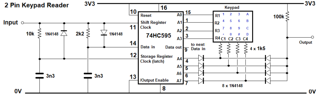 Edited 2026-02-27 10:27 by phil99 |
||||
| The Back Shed's forum code is written, and hosted, in Australia. | © JAQ Software 2026 |
