
|
|
Forum Index : Windmills : my Lenz2 attempt
| Author | Message | ||||
vawtman Senior Member Joined: 14/09/2006 Location: United StatesPosts: 146 |
Gary, Your turbine being only 3ft diameter will be agood match for a small axial if all you need is low voltage to charge a battery. My Darrieus is 8ft diameter(blades have much farther to travel) and i plan on feeding elements so the idea is to run high voltage.54pl 108cls 2ph.Playing with stator mounting thoughts now. Good luck and you will learn alot along the way  |
||||
oztules Guru Joined: 26/07/2007 Location: AustraliaPosts: 1686 |
[quote]I never questioned that. What I was thinking was his stator was designed for a hawt that turns alot faster [/quote] This style of alternator allows you to wind it for any speed you choose. It is the efficiency and flexibility that causes me to recommend the axial for your project. If you find you have not got enough revs for the stator, just wind one with more turns and your back in business. The kicker is that you may have to use thinner wire to fit the winding window, but unlike the radial, you can also move the plates further apart to get more real estate to wind in with thicker wire, and maybe match it that way. Dinges has just posted a Femm simulation, which will give you some idea of the flexability of the axial. Remember, with wind thinggies, not everything is clear cut. In looking at the simulations, one is tempted to go for the most flux, closest plates etc..... in reality, a good compromise between winding space, flux, and stator strength is better. Like everything in the world there are exceptions.... like Gordons AxFx. I don't know how he built the thing ... but it could not have been easy. ..............oztules Village idiot...or... just another hack out of his depth |
||||
| oztules Guru Joined: 26/07/2007 Location: AustraliaPosts: 1686 |
Sorry Vawtman, This button is the one I was referring to : "world" 
which is next this this button.. "U" (not smart enough to think to do an underline like this U " 
Hope that clears that up a bit 
.........oztules Village idiot...or... just another hack out of his depth |
||||
| vawtman Senior Member Joined: 14/09/2006 Location: United StatesPosts: 146 |
Ed help I think i got it oz  He's been helping Vawties there. come join in. He's been helping Vawties there. come join in. |
||||
gj4533 Newbie Joined: 28/12/2008 Location: United StatesPosts: 19 |
Followed Ed's directions and made my forst stator. It turned out very nice. I used a piece od corian for the mold and the top and bottom is made of 3/4 melamine. Next is the magnet plates. probably this weekend. Thanks to Ed. 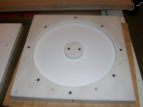
G.Johnston |
||||
| Gizmo Admin Group Joined: 05/06/2004 Location: AustraliaPosts: 5182 |
Hi G That turned out looking good, very neat work. Keep us posted. Glenn The best time to plant a tree was twenty years ago, the second best time is right now. JAQ |
||||
| GWatPE Senior Member Joined: 01/09/2006 Location: AustraliaPosts: 2127 |
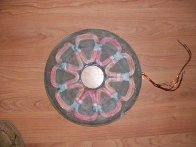
Hi gj4533, looking pretty good so far. This looks like a 12 magnets per rotor 1"x2"x0.5" block design. This has 24 cu in magnet volume. It will be interesting to compare notes, as my new AxFx unit will have the same magnet volume, but with round disks, and 8 magnets per rotor with 24 cu in total magnet volume. I will have round coils as well, and only 6 coils. The wiring tails on my unit will come out in the centre. It is probably too late for you, but I will be moulding in flexible wiring tails to my new AxFx stator. What will the magnet rotor separation end up to be? Gordon. become more energy aware |
||||
| Tinker Guru Joined: 07/11/2007 Location: AustraliaPosts: 1904 |
Gordon, the above detail got me curious. How do the wires then go past the magnet rotor disk(s) to get to an accessible place for connection? I'm trying to picture the mechanical arrangement in my head and wonder what clever idea you came up with. Klaus Klaus |
||||
| GWatPE Senior Member Joined: 01/09/2006 Location: AustraliaPosts: 2127 |
Hi tinker, I will explain some more on the F&P@PE thread if you like. Gordon. become more energy aware |
||||
| Tinker Guru Joined: 07/11/2007 Location: AustraliaPosts: 1904 |
Yes please. Tinker Klaus |
||||
| gj4533 Newbie Joined: 28/12/2008 Location: United StatesPosts: 19 |
I'm not sure how far to put the magnets away from the coils, I was thinking between .02" and .03" on each side. I've included the CAM program picture for how the magnet plates look. The magnet plates are 8.25' amd the stator is 11" so there is 1 3/8" on each side to mount the stator to the mill frame. The magnets are the wedge type and I'm going to cut the face of the plate .02" or .03 deep to position them where they need to be. The hole through the plate is 24mm and I like the slot and tang to keep them aligned with each other. The programs are written, now I'm just waiting for the machine to open up so I can make them. 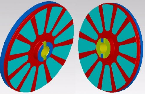
this is only the magnet side program, the other side will be turned down and set screws will be added. Also on the small diameter of one of these plates there will be drilled and tapped holes for assembly purposes to jack the plates into place (2000 lbs of pull is not easy to keep apart). I'll post the real pictures of them as soon as I make them. Gary G.Johnston |
||||
| GWatPE Senior Member Joined: 01/09/2006 Location: AustraliaPosts: 2127 |
Hi gj4533, I think you will have your work cut out with 0.02". This only allows 0.01" per side. I will be allowing at least 0.04"[1mm] per side on my new unit. There may be some distortion in operation and you don't want to wear away the coils. Gordon. become more energy aware |
||||
| gj4533 Newbie Joined: 28/12/2008 Location: United StatesPosts: 19 |
Ok, I did say .02 to .03 per side, I decided .03 per side will do fine for me. I was wondering another thing about the coils and stator. Seeing as there are 2 strands of 65 turns in each coil (2 coils in 1) Why not have all of the wires come out of the stator. In very low RPM you could take each coil and wire it in series to have 130 turns and produce more voltage (less amps) to start charging. In higher RPM change it to parallel (star) to keep the voltage down (more amps). Even higher rpm switch it to delta for even more amps. What do you think? Gary G.Johnston |
||||
| gj4533 Newbie Joined: 28/12/2008 Location: United StatesPosts: 19 |
Ran the first side of the magplates today. After messing with the program I got them both done. The back side still needs to be turned down and drilled and tapped but this side is the harder side to get done. It is nice having the 4 axis dual spindle live tooling turning center at my disposal (it's the machine I run at work) and having the opportunity to use it when no one is around. The plate on the right side has 1 magnet in place. Now to finish it and assemble everything. There is .03" of clearance on both sides Gary 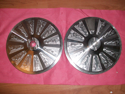
G.Johnston |
||||
| oztules Guru Joined: 26/07/2007 Location: AustraliaPosts: 1686 |
Very impressive project so far. Great looking stator, beautiful disks...I look forward to seeing the results in the breeze. All the best with this. ............oztules Village idiot...or... just another hack out of his depth |
||||
1woodman Newbie Joined: 18/10/2008 Location: United StatesPosts: 3 |
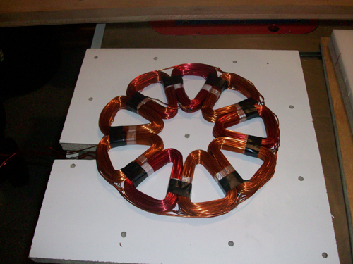
Here is the winding jigs I made to wind the 2 strands at a time for the coils. 

The scary part to me is assembling the mag. plates. I know Ed says to put some 3/4 wood spacers between the coils and the last mag. plate you slide over the shaft. At what distance do you feel the plates pull together, could be a nastey finger smashing experience? The closer one comes to the truth, the more he is approached by a lie.Infowars.com |
||||
| oztules Guru Joined: 26/07/2007 Location: AustraliaPosts: 1686 |
From about 4" and inwards I found that things started to get a bit difficult... from 3" it is scary... 2" is out of control, and at 1" it is in the many hundreds of pounds. These were 24 2"x1/2" rounds on 8mm plates. To say they can cause damage is an understatement. Provided you have a reliable jacking system it is no problem. Don't try it until you do have a system in place, or you will struggle to get it apart again.... if you still have fingers that is
..........oztules Village idiot...or... just another hack out of his depth |
||||
| 1woodman Newbie Joined: 18/10/2008 Location: United StatesPosts: 3 |
Any one have a pic. of a jacking system? A gear puller type set-up? The closer one comes to the truth, the more he is approached by a lie.Infowars.com |
||||
| GWatPE Senior Member Joined: 01/09/2006 Location: AustraliaPosts: 2127 |
The jacking system has to be an integral part of the machine, for best results and safety. Long threaded bolts are what I use. Gordon. become more energy aware |
||||
| gj4533 Newbie Joined: 28/12/2008 Location: United StatesPosts: 19 |
Here is a couple of pictures of the jacking system I integrated into the design of the magnet plates 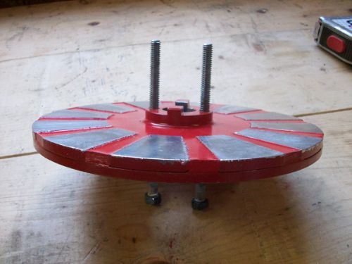
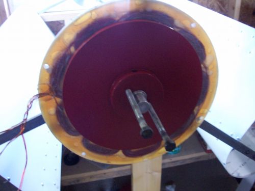
with this system I can try different stators because I can very easily seperate the plates Gary Johnston G.Johnston |
||||
| The Back Shed's forum code is written, and hosted, in Australia. | © JAQ Software 2026 |
