
|
|
Forum Index : Microcontroller and PC projects : Waveshare 7 & 10" DVI displays
| Author | Message | ||||
| Mixtel90 Guru Joined: 05/10/2019 Location: United KingdomPosts: 8965 |
Oh, that's so nice of them. NOT! No problem, I allowed for 0R links too.... ;) The story so far: A nother piccie 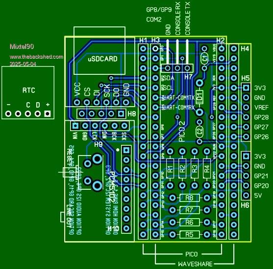 A startat amanual info.zip Mick Zilog Inside! nascom.info for Nascom & Gemini Preliminary MMBasic docs & my PCB designs |
||||
| IanT Senior Member Joined: 29/11/2016 Location: United KingdomPosts: 131 |
And even a Manual Mick! You really are spoiling me (just as well, I need all the help I can get!) :-) Regards IanT |
||||
| Mixtel90 Guru Joined: 05/10/2019 Location: United KingdomPosts: 8965 |
It's changed a bit more. :) The Reset button is now on the end, with the screen control buttons. The notch has gone and the board has rounded corners. I now know it will fit because I've overlaid it on a photo of the Waveshare board. :) This seems to be a reasonably priced display, which is why I'm making a proper job of the design. It might be of interest to others. An option might be a second board mounted on the lower two fixing pillars that holds the components for a 4-port USB hub or a PS2 keyboard. I've no idea how strong those pillars are, could they be used like the VESA fixings on a monitor? Mick Zilog Inside! nascom.info for Nascom & Gemini Preliminary MMBasic docs & my PCB designs |
||||
| mozzie Guru Joined: 15/06/2020 Location: AustraliaPosts: 404 |
G'day, that board is looking good Mick, hopefully the following will help. The M2.5 mounting bushes on the board are solidly soldered to it and will be suitable for mounting to, however the board is only attached to the screen with double sided foam tape, although it is pretty strong stuff and the screen is quite light. The headers for the Pico2 on my board are slightly offset (0.25mm) to the right and the top header C/L is 2.0mm below the C/L of the mounting bushes (see pic) Do you think it might be a good idea to make the board extend over the mounting bushes so they can be screwed together if this is going to be portable? 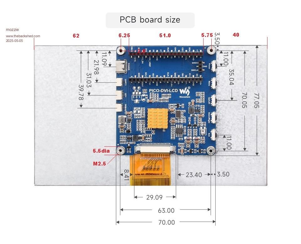 Regards, Lyle. |
||||
| Mixtel90 Guru Joined: 05/10/2019 Location: United KingdomPosts: 8965 |
I can do that if you like. Just the top holes or a full piggyback board? I don't want to obstruct that heatsink too much as I've no idea how hot it gets. Looks like it's safe enough to assume that the screen won't be hanging off those M2.5 pillars. :) I'd want something more solid personally - maybe metal to metal using sticky pads. I was only wondering if it was safe to mount things on them or if they might be used in future. My photo overlay isn't perfect due to distortion in the picture, but I think it's plenty accurate enough. I tried to export the pic but it won't include the scanned image. Mick Zilog Inside! nascom.info for Nascom & Gemini Preliminary MMBasic docs & my PCB designs |
||||
| Mixtel90 Guru Joined: 05/10/2019 Location: United KingdomPosts: 8965 |
OOPS! I got carried away... 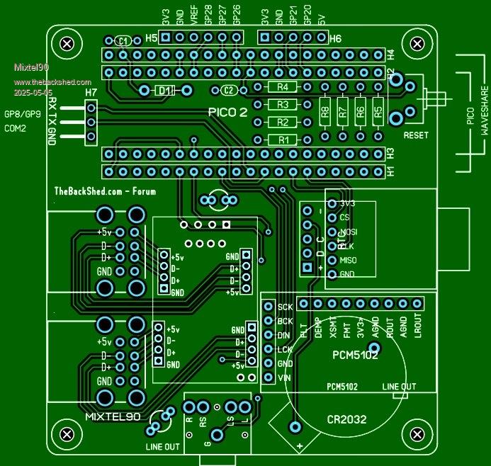 You need a little USB lead to plug into the Pico. The other end can be soldered to the hub module. The hub plugs in, but the connectors are 2mm pitch turned tin type as I've found these to be more tolerant of the strange connector positions on the module! No links are needed for programming as you have to unplug the USB connector, which also disconnects power from the hub. The 3.5mm audio jack may not be needed, but the one on the audio module might be a bit obstructed by the CR2032 holder when using larger plugs. SL6 has no 3D capability so it's not all that easy to visualize. Length of the M2.5 spacers will obviously depend on the length of the long-pin female headers, but IMHO you should be looking to get at least 5mm unobstructed over the top of the heatsink. Knowing my luck standard size spacers will require a non-standard header pin length. Mick Zilog Inside! nascom.info for Nascom & Gemini Preliminary MMBasic docs & my PCB designs |
||||
| IanT Senior Member Joined: 29/11/2016 Location: United KingdomPosts: 131 |
As my Grandchilden like to ask "Are we there yet?"  IanT |
||||
| Mixtel90 Guru Joined: 05/10/2019 Location: United KingdomPosts: 8965 |
That's an excellent question! :) Topsy just growed... Mick Zilog Inside! nascom.info for Nascom & Gemini Preliminary MMBasic docs & my PCB designs |
||||
| mozzie Guru Joined: 15/06/2020 Location: AustraliaPosts: 404 |
G'day, Always thought the journey was the fun part, kids may not agree..... Mick, that board is looking excellent. The bushes on the board are 4mm high, so with a standard 8mm long standoff we have 12mm, this works with the extended headers commonly available and gives us 5.5mm above the heatsink which doesn't seem to get overly warm anyway, WIN WIN  Also see below for my preferred mounting setup for PICO2 with USB, this was going to be posted in the PICO2 HDMIUSB reference design thread but not sure if you would like to accommodate it here as well as an option to using a micro usb plug. 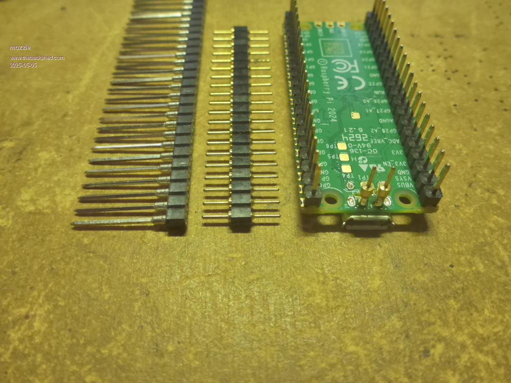 Cut the pin off one end of the M/M header shown centre and solder to USB connections 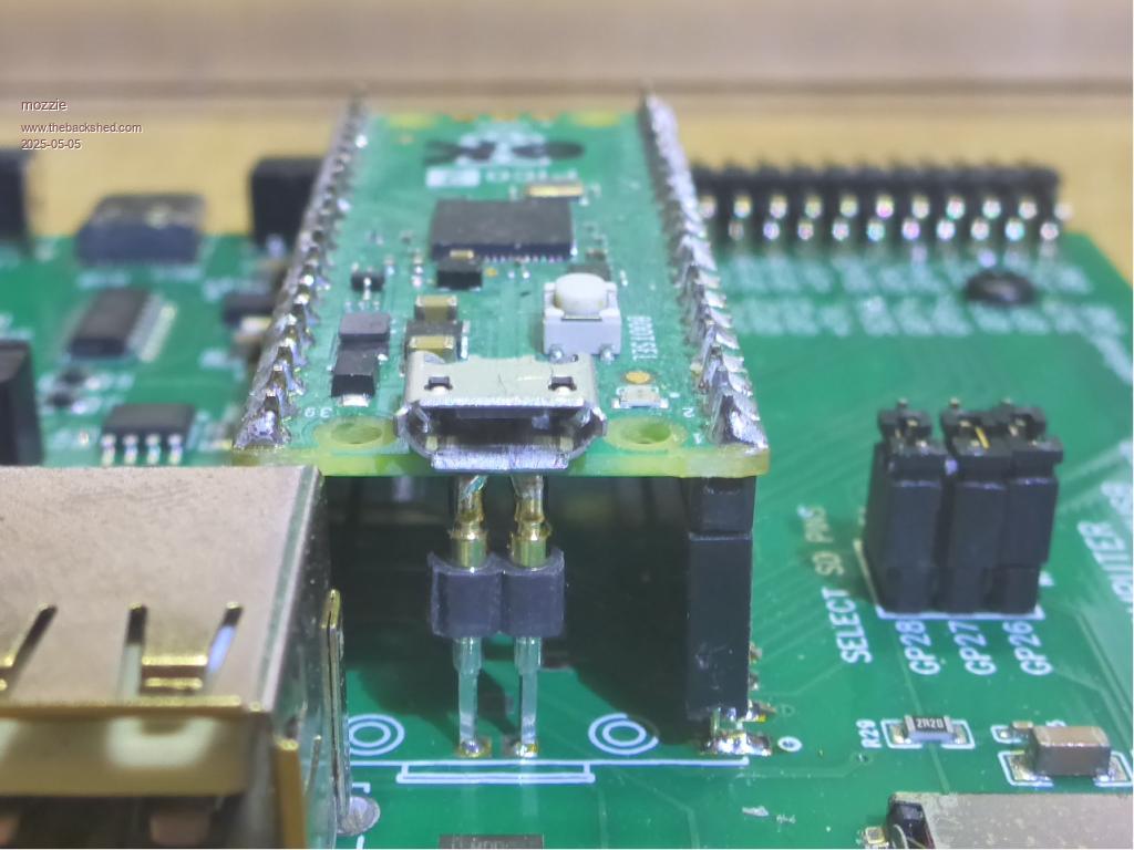 Finished product. The idea of soldering the PICO in and then frying it somehow (I'll find a way) makes my head hurt  |
||||
| Mixtel90 Guru Joined: 05/10/2019 Location: United KingdomPosts: 8965 |
I don't want to solder in the Pico here. There's nothing to be gained. I'd have to fit switches or links to disconnect D+/D- while installing MMBasic and there isn't much room. Unplugging its USB is fine as the plug is already behind the display and it gives perfect isolation (and is foolproof!). There's no problem with height as the Pico, USB sockets, Audio and RTC modules are all roughly the same height. Mick Zilog Inside! nascom.info for Nascom & Gemini Preliminary MMBasic docs & my PCB designs |
||||
| Mixtel90 Guru Joined: 05/10/2019 Location: United KingdomPosts: 8965 |
After me saying that I didn't want to include PS2 due to possible mechanical problems it seems a bit petulant to refuse to fit it now that the board is securely fastened down. So, this morning's news is that there will now be a choice - you can include either the USB hub and its sockets or a PS2 socket and its level shifter (it's the same PCB design so you can build a couple of each if you like!). :) Sorry, you can't mix PS2 and USB but there are limits! I've just laid out the board and done the point to point test and DRC in SL6 and I think this might be the final design. I'll finish tidying it up and get the Gerbers sorted out. Mick Zilog Inside! nascom.info for Nascom & Gemini Preliminary MMBasic docs & my PCB designs |
||||
PilotPirx Senior Member Joined: 03/11/2020 Location: GermanyPosts: 127 |
Sounds very promising. You could build a portable device. What tips do you have for a small keyboard? |
||||
| Mixtel90 Guru Joined: 05/10/2019 Location: United KingdomPosts: 8965 |
No preference really as I always prefer normal ones. I have enough problems hitting normal size keys. :) The board is suitable for any normal USB or PS2 keyboard. You could also patch in a small I2C one if you can find one that works. No bluetooth keyboards unless they use a USB dongle. It's years since I last bought a keyboard. :) The overall thickness might be a bit bulky for a laptop-style portable device. There's probably about 30mm above the back of the Waveshare board to the back of the USB sockets. Probably more like a small desktop machine. Mick Zilog Inside! nascom.info for Nascom & Gemini Preliminary MMBasic docs & my PCB designs |
||||
| dddns Guru Joined: 20/09/2024 Location: GermanyPosts: 875 |
Looks amazing. How fast does that spindle turn? Don't want to show off but it fits for the interested and this The ssd1963 has one big advatage, it has its own screen buffer and displays full colour at 800x480 really brilliant in photo quality. Downside is, that PicoMite supports full color not in full extent but with 16 colors a frame buffer works on RP2350 with PSRAM and blit works in full color and is very fast. I think no other supported display has a nicer picture. But TFT and very poor viewing angle, touch works excellent If its relevant you have probably the most free ram space for your code photopaint with magnifier 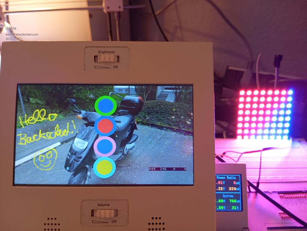 sorry!! of cause I wanted to write Backshed but the german sch is deep in me :) edit2: This is really nothing special and achievable for everyone as it takes about 30 lines of beginners code to have such result Edited 2025-05-07 04:16 by dddns |
||||
| Mixtel90 Guru Joined: 05/10/2019 Location: United KingdomPosts: 8965 |
And here it is! This design *should* work. I've not been able to find anything that might stop it. However, if the circuit diagram is screwed up somewhere I take no responsibility. I can only work with the info that I have. :) construction pack.zip Mick Zilog Inside! nascom.info for Nascom & Gemini Preliminary MMBasic docs & my PCB designs |
||||
| IanT Senior Member Joined: 29/11/2016 Location: United KingdomPosts: 131 |
Thank you very much Mick, that all looks excellent to me (far better than anything I could have managed). I'm not an expert on JLCPCB, so I just pointed the site at your Gerbers and it all seemed to load OK. I've left the settings as they initially appeared, except the PCB colour (as I prefer 'Blue' ones). It seems there is only a pound or two difference between Qty 5 and Qty 10 boards, most of the cost is in shipping which remains the same for both. So I'm going to order Qty 10. I will need three and probably give another two or three away. If anyone else wants one (or more) I can increase the quantity if required but I'd like to get this order under way ASAP (eg today). The PCB cost will be about £2 each, plus postage. If you are not in UK, then I don't know what the shipping/duty costs might be for elsewhere (EU/US/Aussie/NZ) but if you are happy to cover the initial cost of overseas Royal Mail postage and accept any further Import/VAT etc charges then I'd be pleased to help. So - Anything else I need to worry about or have forgetten? Regards, IanT |
||||
| Mixtel90 Guru Joined: 05/10/2019 Location: United KingdomPosts: 8965 |
Sending a single small board to just about anywhere is very reasonable. You can use ordinary international letter post as they fit well within the size and weight limits, even if you put a bit of thin card round them. As a private letter there are no other costs. Mick Zilog Inside! nascom.info for Nascom & Gemini Preliminary MMBasic docs & my PCB designs |
||||
| mozzie Guru Joined: 15/06/2020 Location: AustraliaPosts: 404 |
G'day, that board looks excellent Mick, thanks for your time and effort IanT, if you have not ordered them already, can I possibly put my name on one? I have a design in mind but with the "to do" list it'll be 2 years before it gets done. dddns, that unit is very impressive, the SSD1963 screens are great but I think this wins out on simplicity. The Micro Die Grinder does 70,000 RPM flat out at 90PSI according to the label. Regards, Lyle. Edited 2025-05-08 07:58 by mozzie |
||||
| dddns Guru Joined: 20/09/2024 Location: GermanyPosts: 875 |
This number is more than impressive for @home in any way..Congrats! Had a chat with a dentist and it's extremely expensive. All the best for your project! |
||||
| IanT Senior Member Joined: 29/11/2016 Location: United KingdomPosts: 131 |
I finished my "other duties" a bit late last night, so held off ordering until this morning. I've just ordered Qty 10 boards and will also get some other parts (like the 10" screens) on their now way too. I need to check my component stocks to see what else I need. Given recent comments elsewhere on TBS, I think it will be PS2 keyboards (rather than USB) for the kids. I can get what look like good quality new/old stock keyboards for about the same price as USB ones... Lyle/Mick - If you let me have your addresses (by PM) I'd be very pleased to send you both one (at no charge). Thank you for the idea Lyle and thank you very much for your time and effort on the PCB design Mick. Regards, IanT |
||||
| The Back Shed's forum code is written, and hosted, in Australia. | © JAQ Software 2026 |
