
|
|
Forum Index : Microcontroller and PC projects : The 2350B 64 pin board for my CNC
| Author | Message | ||||
| phil99 Guru Joined: 11/02/2018 Location: AustraliaPosts: 3321 |
A microbridge is perfect. |
||||
| PhenixRising Guru Joined: 07/11/2023 Location: United KingdomPosts: 2005 |
This was my philosophy since forever but the only failure that I can remember was when someone, somehow managed to apply 110V AC to a 24V DC input. These carrier boards are inexpensive enough that I'll include spares in a care-package. I was just populating a breadboard and even though I do this frequently, I still managed to bend a pin, even when using my pin straightening tool. |
||||
| Mixtel90 Guru Joined: 05/10/2019 Location: United KingdomPosts: 8965 |
TBH I'd always try to avoid sockets in industrial stuff. They are always a weak point. If you have to use them then use good ones as the risk of corroded pins is less. Opto-couplers are very rugged. If you want belt and braces fit a series resistor then a zener before the opto's series resistor. Use it to limit the opto's maximum current to about 10mA at the zener voltage. The zener will also give reverse polarity protection. Mick Zilog Inside! nascom.info for Nascom & Gemini Preliminary MMBasic docs & my PCB designs |
||||
Bryan1 Guru Joined: 22/02/2006 Location: AustraliaPosts: 2161 |
Well opened up Sprint Layout yesterday only to find the wheel on my logitech mouse was completely stuffed  and was forced to shut Sprint Layout down. So went to the place I bought it from only to find it was 13 months ago so out of warranty and was forced to shut Sprint Layout down. So went to the place I bought it from only to find it was 13 months ago so out of warranty  anyway $14 for a new mouse and now got 2 dongles on the the USB front ports on my desktop. also grabbed a 4 port unpowered USB hub for the project. anyway $14 for a new mouse and now got 2 dongles on the the USB front ports on my desktop. also grabbed a 4 port unpowered USB hub for the project. |
||||
| Mixtel90 Guru Joined: 05/10/2019 Location: United KingdomPosts: 8965 |
Mice seem to have a habit of dying at the least convenient time. :-( I've now accumulated a standby wireless one and a couple of wired ones that I can use in case of emergencies. Mick Zilog Inside! nascom.info for Nascom & Gemini Preliminary MMBasic docs & my PCB designs |
||||
| Bryan1 Guru Joined: 22/02/2006 Location: AustraliaPosts: 2161 |
Well I have been letting my shed run 24/7 as the load with my beer fridge and the lights is only a 5 amp draw on the inverter anyway with the last week it has been cloudy as and when I looked on my victron app saw over night lows of 22 volts  So checked the gravity in my shed battery and yep flat as a tack  so spent the last 2 days with the inverter off charging the battery and with no load on the battery over night it will be interesting to see the low voltage using the app. so spent the last 2 days with the inverter off charging the battery and with no load on the battery over night it will be interesting to see the low voltage using the app.Anyway toady spent most of the day working on my CNC where I mounted the DM556's on the sides of the top tray. Now just got to run all the step/direction cables to that breakout board I made then it will be ready to test with that code again. |
||||
| Bryan1 Guru Joined: 22/02/2006 Location: AustraliaPosts: 2161 |
Well got some wild weather here and over night my ol' trusty F&P wind genny fully charged the shed battery  Anyway unwound some Cat6 cable to use for the data lines and slowly getting there wiring it up, now got all the limits and E-stop wired upto the expansion board and with every connection checking with my DMM to enure continuity. I still need to setup my breadboard with a 2040 and that ILI9488 LCD so got some visual when testing out that direction/step code. Once it's wired up I will take a pic to show how it's all wired up then the fun can start. Cheers Bryan |
||||
| Bryan1 Guru Joined: 22/02/2006 Location: AustraliaPosts: 2161 |
Ok got it all wired up and all checked so the next step is setting up the 2040. Now on the left picture one can see that green board thats where all the wires go and put separate green lugs for the output. The red and green wires are for the spindle motor and the blue and black are 2 spare inputs from the motor connection so a trace can be later made and used. 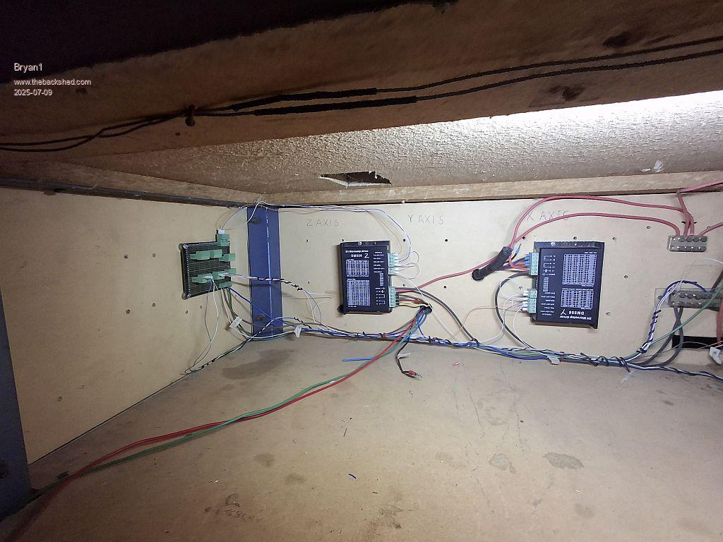 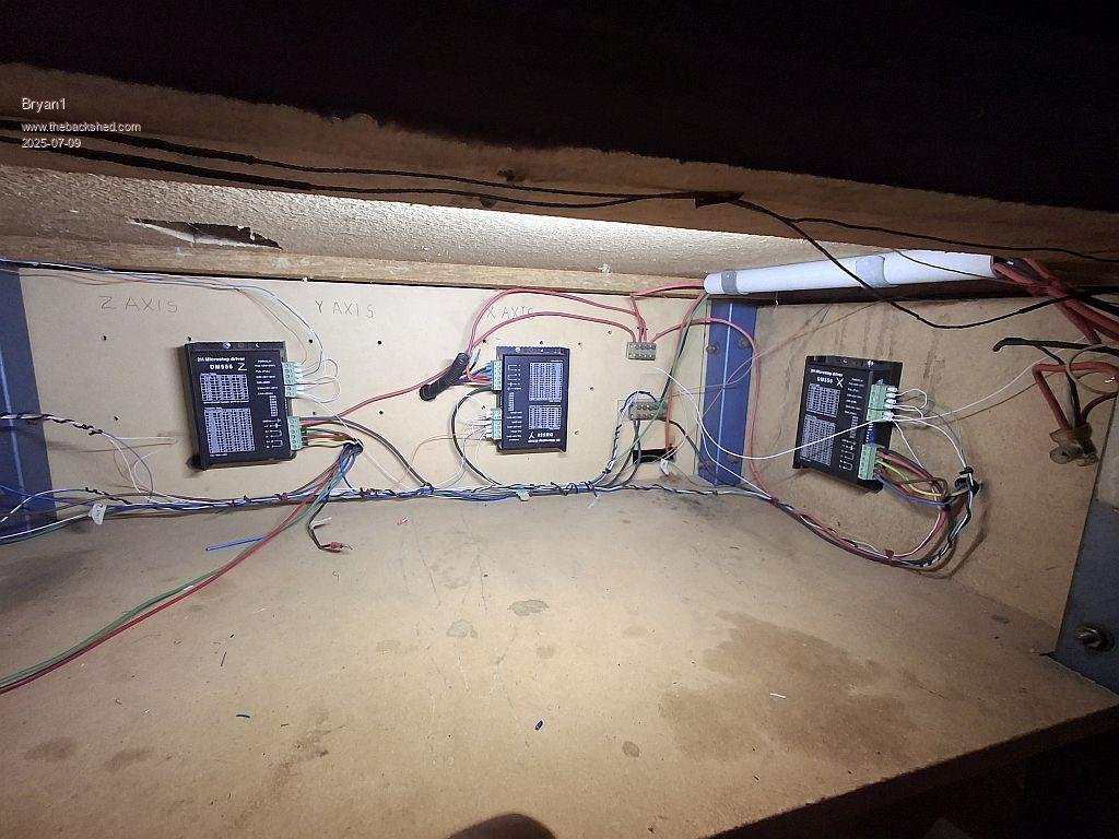 I did have the right termination fittings for the cat6 wire and each DM556 has been pulled down to earth so a high signal will be needed. Did this before with the test so it shouldn't be a problem. |
||||
| PhenixRising Guru Joined: 07/11/2023 Location: United KingdomPosts: 2005 |
Now would be a good time to check your fire extinguisher |
||||
| Bryan1 Guru Joined: 22/02/2006 Location: AustraliaPosts: 2161 |
That wood bench has been on there since day 1 of my CNC mate Now where the X-axis 556 is I did put in a new side for it. As it was dark in the there I just set up a 3 section LED strip which did give plenty of light but also got nice and warm too so once everything is up and working that light won't be needed. I did stick it on using double sided tape and it did fall down a couple of times that when I noticed the warmth. Now the main table is some high voltage switch board stuff that is easily drilled and tapped and being 20mm thick it doesn't bow at all. So if I do have time tomorrow I will be testing each axis and putting a dial indicator on to check travel down to 0.001" Then the huge learning curve can start on the coding and now the V6 manual is out now may just use that $12 colour laser printer to print a copy  If those DM556's do get warm in use I have a heap of heat sinks so they be remounted on them. Now once the CNC is all working I will be moving it out of my shed and down to the area I have in the house shed and it is setup to be be removed from the frame it's currently on. Phenix the CNC has 100x10mm flat bar at each end with that 20 mm board screwed on each end so when I do want to set it up in it's final destination I will more than likely fabricate up a steel frame for it. But between now and then is going to be awhile as I can't see the finish line from here at the present moment. Edited 2025-07-09 19:19 by Bryan1 |
||||
| Bryan1 Guru Joined: 22/02/2006 Location: AustraliaPosts: 2161 |
Now if I'm right a MISO pin on the ILI9488 shouldn't be connected does that mean the same pin for the SDCard is the same. Just want to get this right as I am sick of destroying lcd's Now with all these breakout boards ebay ins't giving me the right one's so some links to them would be great. I did load up 6.03 this morning and MCCC hung then I looked at version I had and did n update and that solved the problem |
||||
| phil99 Guru Joined: 11/02/2018 Location: AustraliaPosts: 3321 |
If you want the SD card to work its SD_DO does need to be connected to MISO. For most purposes the LCD S_DO doesn't need to be connected but if you want to save screen images to a .BMP file it can be done with a diode and resistor. See here. And here Edited 2025-07-11 23:05 by phil99 |
||||
| Bryan1 Guru Joined: 22/02/2006 Location: AustraliaPosts: 2161 |
Well it does look like this ILI9488 lcd is a piece of chinese rubbish Spent most of the day trying to get the lcd working, now what I did find as I had 6.03 on thought I'd try 6.02 and the backlight went off as soon as I did an option reset. So even tried going back to 5.08 and what I saw as soon as I configured the lcd it did the back light did come on. Saw Phil's second suggestion so put the diode and 10K setup in but still no change. Now when I do a backlight change it does go dimmer so the backlight is responding but as far as it recognizing the driver nope nada nothing. |
||||
| phil99 Guru Joined: 11/02/2018 Location: AustraliaPosts: 3321 |
Many of us have them and they work very well. I have several and they produce good clear images. The only issue is reading data back from them requires the 2 extra components. Have you setup OPTION SYSTEM SPI ? Type option list and show the results here. The diode / resistor has nothing to do with the backlight. It is for reading data from the screen, such as saving a .BMP image of the screen. As the BACKLIGHT command is changing the brightness the driver is probably working. Type CLS RGB(green) at the console and the screen should go green. If not switch off and check continuity from the top of each LCD pin to the top of the corresponding Pico pin. Ignore the SDO to MOSI pin as that isn't relevant to getting an image on the screen. |
||||
| Bryan1 Guru Joined: 22/02/2006 Location: AustraliaPosts: 2161 |
Hi Phil when I saw your second suggestion I did go with GP7 for the backlight and as far as the setup goes it's 100% by the manual. Now I thought the issue may have been using a separate power supply as I do have the setup for a the lithium batteries so 8 volts into one of those 600mA buck boost boards with 5 volt output. So I changed it over to powering the LCD from Vbus so the battery wasn't needed but it didn't change a thing. I also hooked up the SDcard and that isn't showing, I even removed all the wiring for the LCD apart from VCC and ground to try and get the SDcard working to no avail. After dinner I will go up to my shed and try that CLS RGB(green), now everytime I redid the wiring I checked each connection with my multimeter to ensure the connection. One thing I did notice when the LCD was powered up pin 18 and 19 were shorted out yet when the LCD was off they weren't shorted. At one pointed after changing the firmware I did type in the option LCDpanel ILI9488 command and got the error system SPI wasn't set Edited 2025-07-13 18:56 by Bryan1 |
||||
| Bryan1 Guru Joined: 22/02/2006 Location: AustraliaPosts: 2161 |
Ok brought the breadboard setup down to the house and found I hadn't installed MMEdit so got it installed and this is the option list option list PicoMite MMBasic Version 5.08.00 OPTION SYSTEM SPI GP18,GP19,GP16 OPTION LCDPANEL ILI9488, RLANDSCAPE,GP15,GP14,GP13,GP7 OPTION TOUCH GP12,GP11 OPTION SDCARD GP22 also brought down my multi meter and checked all the connections which prove right yet when I typed in the CLS RGB(green) no change but doing the backlight did |
||||
| dddns Guru Joined: 20/09/2024 Location: GermanyPosts: 875 |
Hello Bryan, everything is driven through system spi bus. I would connect and configure them step by step to analyze the problem. First I would only connect the display part. after that works then the touch and sdcard as last. Good luck! |
||||
| phil99 Guru Joined: 11/02/2018 Location: AustraliaPosts: 3321 |
Thinking along the same lines as @ddnds and just connected a ILI9488 to a Pico with some jumpers and using your option settings for the LCD but leaving touch and SD pins disconnected. I also left GP16 (MISO - SDO) disconnected as that isn't needed to get a picture. Result - it works, so your options are correct. Next thing to check is supply voltage. Most panels have a 3.3V regulator fitted (U1) so must be supplied with 5V. Some don't have U1 fitted, instead it is bypassed by a 0Ω link (R0) and must only be supplied with 3.3V. Edit. Also checked that the BACKLIGHT command does nothing unless the driver is working. On this test setup I have:- Panel Pico Vdd VSYS (5V) GND GND CS GP13 RST GP14 D/C GP15 SDI GP19 SCK GP18 BL (LED) GP7 Edited 2025-07-13 21:13 by phil99 |
||||
| Bryan1 Guru Joined: 22/02/2006 Location: AustraliaPosts: 2161 |
Ok thanks guy's will try it out in the morning with just the LCD driver also I will load 6.03 on again |
||||
| phil99 Guru Joined: 11/02/2018 Location: AustraliaPosts: 3321 |
You don't need to reload the firmware unless you see other things also going wrong. type:- OPTION TOUCH DISABLE OPTION SDCARD DISABLE If you wish to change any LCDPANEL options first use OPTION LCDPANEL DISABLE then enter the new option. Another thought, perhaps you have been sent the wrong panel. There are several SPI panels that look the same, have the same pins but different controller chips. If all else fails try ILI9481, ILI9341, ST7789_320 etc. Edited 2025-07-13 22:24 by phil99 |
||||
| The Back Shed's forum code is written, and hosted, in Australia. | © JAQ Software 2026 |
