
|
|
Forum Index : Microcontroller and PC projects : Palm Pico - progress
| Author | Message | ||||
| dddns Guru Joined: 20/09/2024 Location: GermanyPosts: 874 |
I like both thoughts. The display driven in the low resolution is good for compatibility and the gaming use case. And with 800x480 and 100x40 characters in Font 1 it is no problem to edit a bigger program with some line length without loosing the overview. I have two PGA2350 and both run super solid @360MHz and when ordered from Germany, the delivery took like only 5 days and 12,50€ each. The keyboard is great! Best wishes and success! Edit: Will the new driver replace Option LCD320 and will it go into RP2040 firmware? Edited 2025-09-04 03:09 by dddns |
||||
| homa Guru Joined: 05/11/2021 Location: GermanyPosts: 651 |
Yes! I think the changes are great — I was bothered by the 1:1 display anyway. Now, if you could just bring out a version with a touch screen, I wouldn't be able to contain my happiness!  Matthias |
||||
| matherp Guru Joined: 11/12/2012 Location: United KingdomPosts: 11636 |
It will have touch screen. This is the pin assignment - not much left  |
||||
| Volhout Guru Joined: 05/03/2018 Location: NetherlandsPosts: 5994 |
Oops. No pins left. This means that you can use only USB for any form of expansion. Not even a UART pair left. Only I2C could have some extra devices. You could potentially free 3 pins. 1/ I2S -> PWM audio 2/ try to work with 49 keys keyboard (7 rows x 7columns = 14 pins. (currently 5x10=15 pins). 3/ share CS of SD and Touch Currently the expansion connector needs only have 4 pins (I2C/GND/3V3). That is easy. Compatible with Qwiics and other modules. Volhout PicomiteVGA PETSCII ROBOTS |
||||
| matherp Guru Joined: 11/12/2012 Location: United KingdomPosts: 11636 |
The system I2C will be brought to the outside so can be used for expansion. In addition I may bring GP8-GP15 out which would give the option of using the screen in 8-bit mode Edited 2025-09-04 16:37 by matherp |
||||
| matherp Guru Joined: 11/12/2012 Location: United KingdomPosts: 11636 |
Here is the layout for the new design. I'll get some blank PCBs made which will allow me to do the development of the new drivers. The SSD1963 supports 8, 12, 16, 18 and 24 bit transfer modes. Between them they support RGB565, RGB666, and RGB888. So I can have a play to determine the optimum mode that achieves the required performance but with the minimum pin usage - 12-bit mode looks interesting. 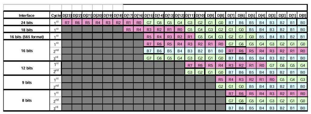 The PCB is 174x133mm and by using a 1260110 lipo it should be possible to keep the thickness down to about 30mm with a 20hr plus battery life. Schematic.pdf 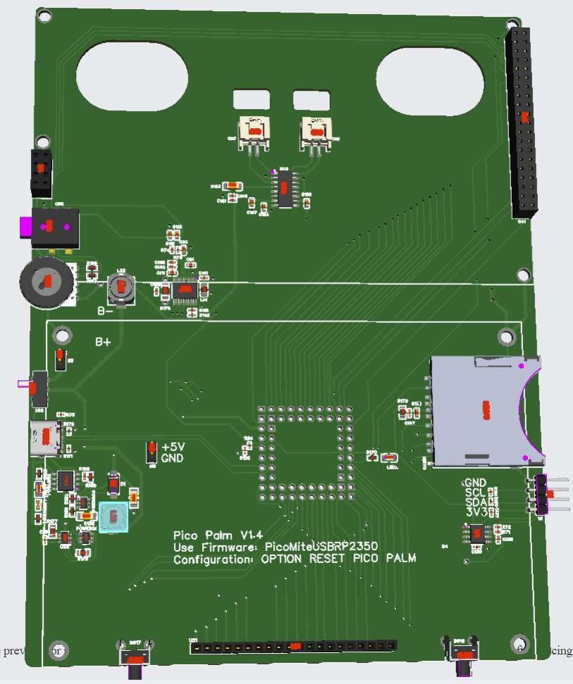 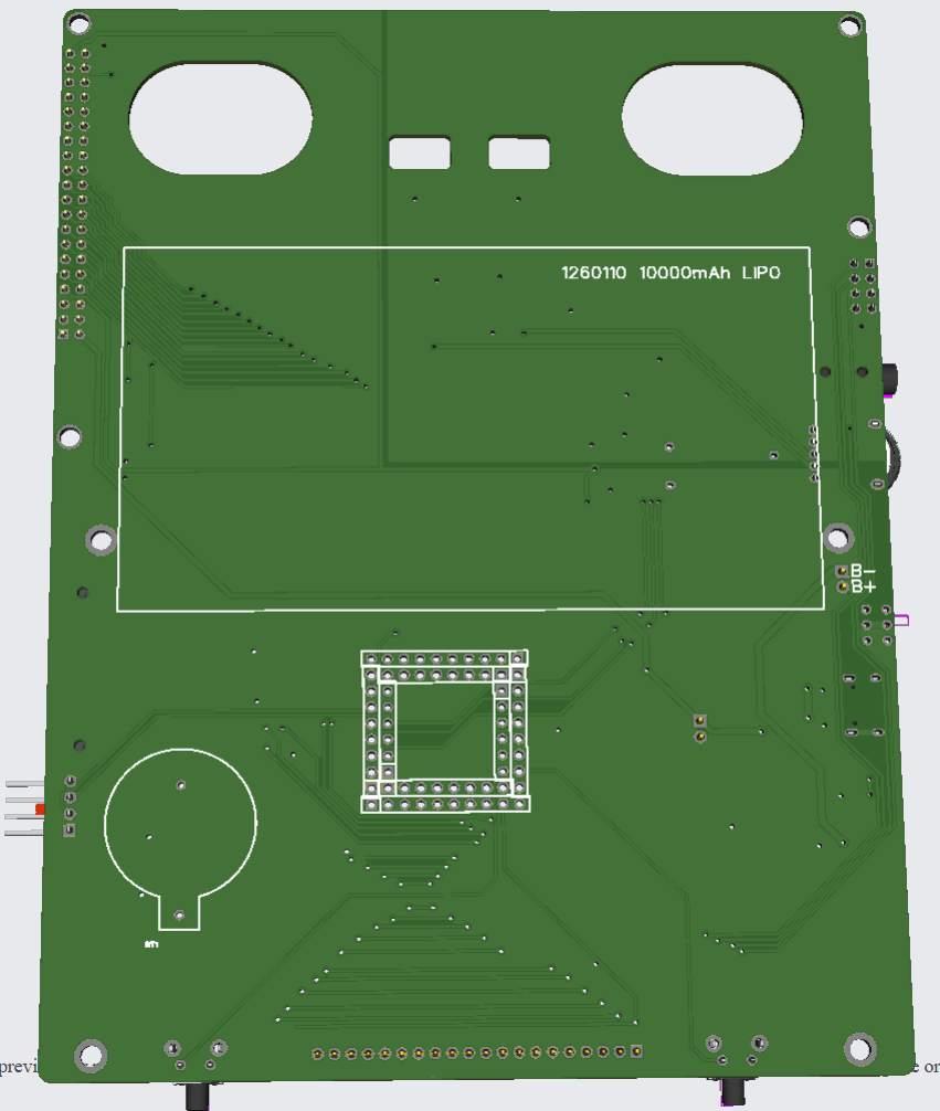 |
||||
| homa Guru Joined: 05/11/2021 Location: GermanyPosts: 651 |
Really, oops, a UART pair would be nice. Why not use an RP2040 on the motherboard and as a keyboard driver for PS2, for example? There may be additional functions in the additional CPU for gimmicks. Matthias |
||||
| Mixtel90 Guru Joined: 05/10/2019 Location: United KingdomPosts: 8964 |
I'm not sure which version of the SSD1963 that is, but doesn't it put a fixing hole right through the volume control? It might be ok, but I was just thinking - for ruggedness of something portable. Just a thought, and probably too complicated now. If the SSD1963 obeyed the CS line it might be possible to multiplex a keyboard on the same data bus, although you'd need to buffer the keyboard data somehow. . Edited 2025-09-05 01:14 by Mixtel90 Mick Zilog Inside! nascom.info for Nascom & Gemini Preliminary MMBasic docs & my PCB designs |
||||
| dddns Guru Joined: 20/09/2024 Location: GermanyPosts: 874 |
I admit, that I think the same as @Homa and @Volhout. -the (professional) use case could be, that this device is a diagnostic and setup instrument for larger machines or something. - free pins are always attractive for the user - if you would choose to use a RP2040 as driver (and running on MMBasic) it would offer another playground for enthusiasts Regards |
||||
| matherp Guru Joined: 11/12/2012 Location: United KingdomPosts: 11636 |
I will try and free some pins possibly using the SSD1963 in 8-bit or 12-bit mode. I won't add a second processor. Makes the whole thing too complex. Two firmware to load and configure. Access to two boot switches and two reset switches etc. This is one of the big flaws with the PicoCalc. Lots of examples of main firmware incompatible with different versions of keyboard firmware. So big NO on that suggestion Edited 2025-09-05 19:28 by matherp |
||||
| homa Guru Joined: 05/11/2021 Location: GermanyPosts: 651 |
Okay, I understand your arguments. I hadn't considered that. Although, the reset would be sufficient for both at the same time. ;-) I was also thinking more of firmware just as a keyboard driver. So, initialise it and you're done. Hence the PS/2 emulation, so that no further special firmware is needed for the 2350. But as I said, the arguments are absolutely understandable. A serial interface would be enough for me. Maybe you could select the 8-bit/12-bit mode via jumper and have more or fewer GPIOs available accordingly. Good luck with the rest of the project! I'm really looking forward to seeing the finished project! Matthias |
||||
| lizby Guru Joined: 17/05/2016 Location: United StatesPosts: 3811 |
Or select 8-bit/12-bit/16-bit mode via jumper PicoMite, Armmite F4, SensorKits, MMBasic Hardware, Games, etc. on FOTS |
||||
| Friday Newbie Joined: 25/08/2025 Location: United StatesPosts: 10 |
Hello, I came to this forum due to the picocalc, I have been watching your board develop with much intrest, I really hope this can become a commercial offering. I would be super happy with what your building. If I could make a 'dumb' suggestion, if your breaking out gp8-gp15 for other uses, maybe put them also out to an edge connector, so people could if they want to add a second pico to talk back and forth via gpio or make little expansion boards with sensors etc on them. Something like. https://www.digikey.com/en/products/detail/sullins-connector-solutions/EBC05DRXN/1318485 so people could even make little atari cartridge like plug ins. This way the main project stays clean like you say, having more than one reset/boot switch is a pain. But people can go crazy on their own time. Good luck, and if there is something a idiot can help with please reach out to me. Aaron |
||||
| toml_12953 Guru Joined: 13/02/2015 Location: United StatesPosts: 685 |
If you're already maxing out the number of used pins, won't going to the Pimoroni make the situation worse? I'd think having all those extra pins would make your job easier. I have both the DIL and Pimoroni so I'm set either way. One advantage of the Pimoroni to the group: If you do go with the Pimoroni, I'll give away four fully populated DIL boards to members here. |
||||
| Mixtel90 Guru Joined: 05/10/2019 Location: United KingdomPosts: 8964 |
The PGA2350 has no predefined GP pins at all apart from GP47 being set up for PSRAM by default - and that can be disconnected via a solder blob link underneath. I've also run a Kynar wire link from there to GP0 to change the PSRAM CS so that I can have GP47 as GPIO. Mick Zilog Inside! nascom.info for Nascom & Gemini Preliminary MMBasic docs & my PCB designs |
||||
| matherp Guru Joined: 11/12/2012 Location: United KingdomPosts: 11636 |
Here is the version I'm getting made. 10 pin header at the top, GND, GP8-15, VCC + solder jumpers to the DB8-DB15 pins on the display. I'm getting them unpopulated to keep cost down but that will give me all I need to develop and test the various options for the display driver with reliable connections. 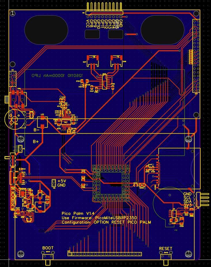 |
||||
| toml_12953 Guru Joined: 13/02/2015 Location: United StatesPosts: 685 |
I'd like to be an early adopter. Posting the build details would be great! |
||||
| Friday Newbie Joined: 25/08/2025 Location: United StatesPosts: 10 |
I would love to be an early adopter what does the pricing look like? |
||||
| matherp Guru Joined: 11/12/2012 Location: United KingdomPosts: 11636 |
Things are looking good. I've got the final PCB layout in and everything works as expected. I've been tuning the screen driver and am getting incredible update rates - full screen draw in 0.2mSec. I've decided that rather than making a box I'm going to go for a PCB sandwich. Top layer with cutout for the screen and keyboard. The main PCB with the keyboard PCB mounted off it and then a blank back PCB. The final assembly will be 174x137x30mm. The unit uses 460mA running gui test lcdpanel and playing an mp3, 10000mAh Lipo for power which should give a run time of around 20 hours on battery. Here is a brief demo of it running Petscii - unfortunately I don't play games and have no idea what I'm supposed to do to play but at least you can hear the sound and see the graphics 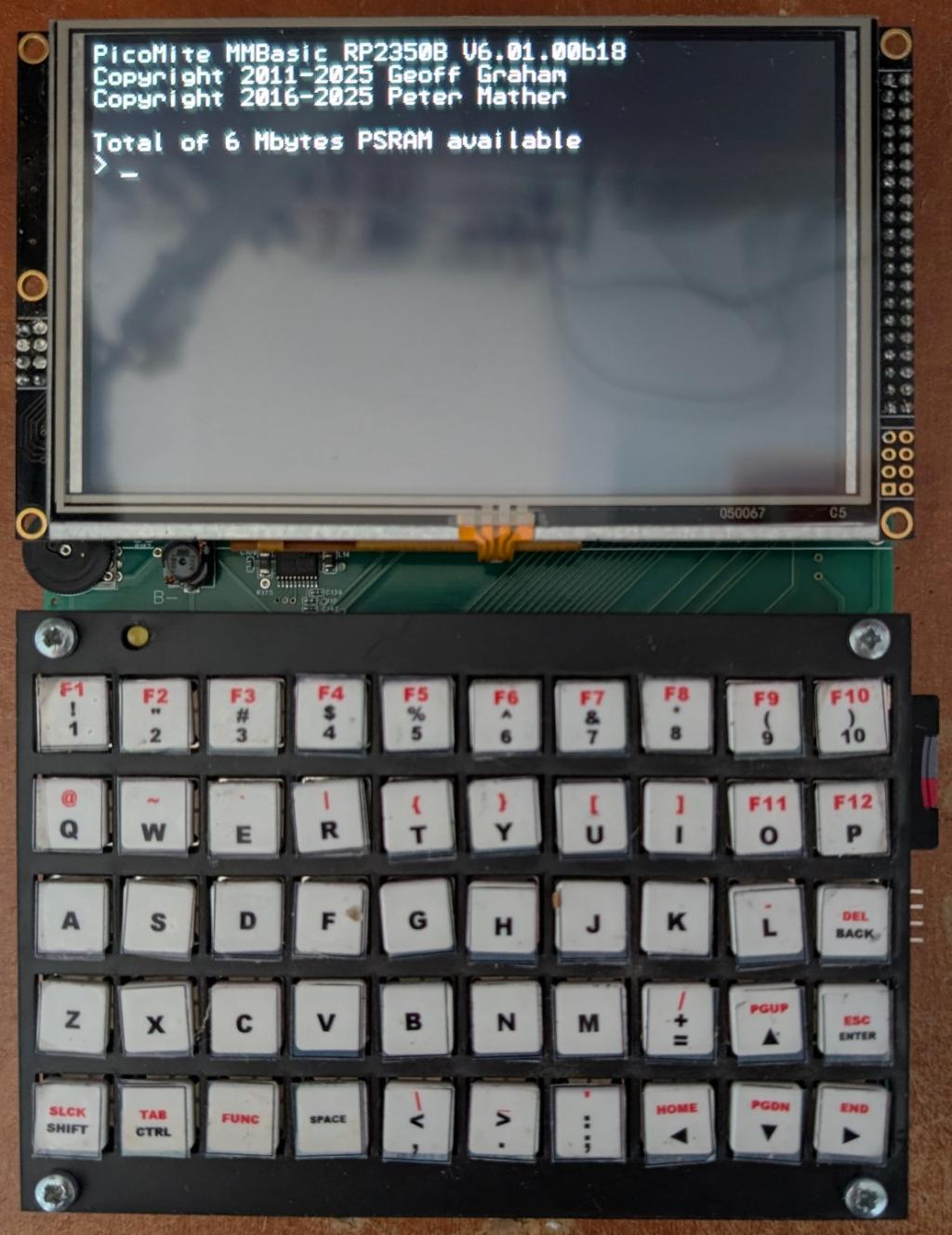 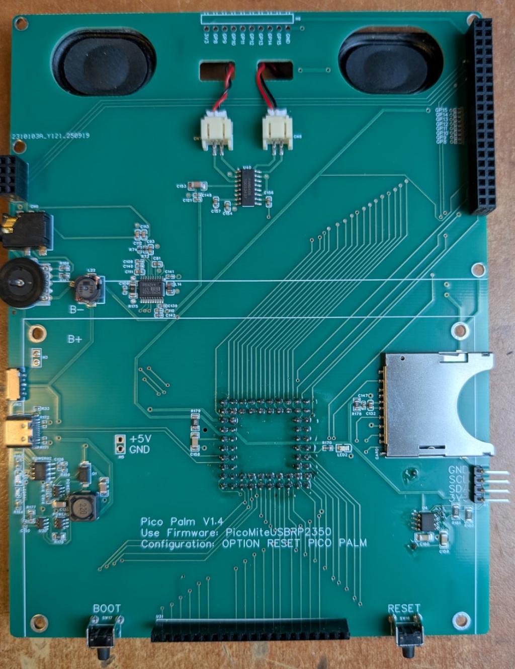 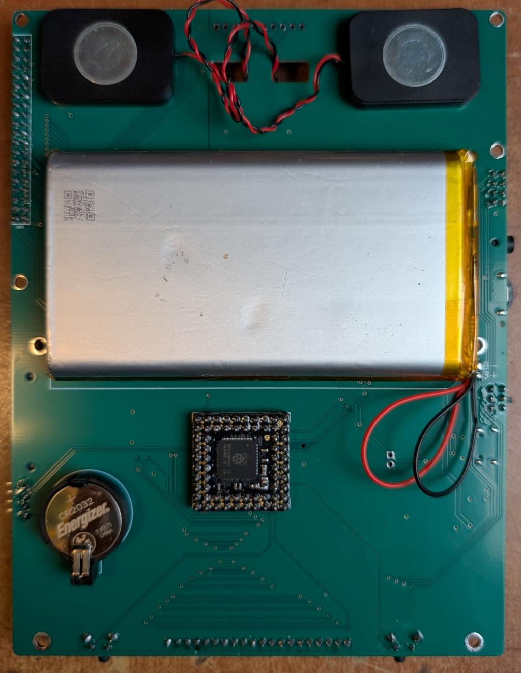 Top PCB overlay 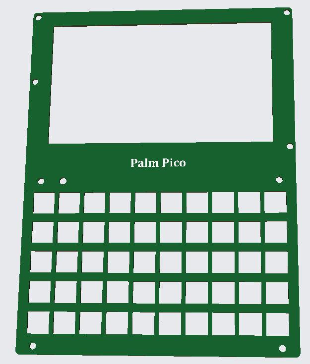 |
||||
| homa Guru Joined: 05/11/2021 Location: GermanyPosts: 651 |
That's incredible, Peter.  I'm really looking forward to it... |
||||
| The Back Shed's forum code is written, and hosted, in Australia. | © JAQ Software 2026 |
