Notice. New forum software under development. It's going to miss a few functions and look a bit ugly for a while, but I'm working on it full time now as the old forum was too unstable. Couple days, all good. If you notice any issues, please contact me.
Greenbelt Guru Joined: 11/01/2009 Location: United StatesPosts: 566
Posted: 07:30am 17 Jul 2009
Copy link to clipboard
Print this post
Time has proven that I am blind to the Obvious, some of the above may be True?
Tinker Guru Joined: 07/11/2007 Location: AustraliaPosts: 1904
Posted: 01:19pm 17 Jul 2009
Copy link to clipboard
Print this post
Floodrod, you picked a difficult job for your first welding Those pipe elbows are cast steel and the pipe is steel, this might need a special welding rod. Klaus
Tinker Guru Joined: 07/11/2007 Location: AustraliaPosts: 1904
Posted: 01:23pm 17 Jul 2009
Copy link to clipboard
Print this post
Stick around here, I will post some pictures once the new frame is up.
I do like 'tinkering' and my first efforts are not something I would show off here, it got to work properly first .Klaus
floodrod Regular Member Joined: 08/07/2009 Location: Posts: 70
Posted: 03:59pm 17 Jul 2009
Copy link to clipboard
Print this post
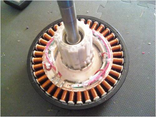
Thanks for the answers.. I eyeballed it again and am a little confused. I took some close-ups so I can make sure I get this right.. Sorry for my constant questioning and lack of knowledge.
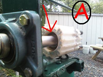
GWatPE, As I understand, you are suggesting shimming between the shaft blocker ridge (Picture A) and the bearing? So I will have to find washers that will fit around the shaft but fit inside the plastic housing ring? If I did this, I would imaging it would cause even more friction on the bearing. Perhaps I am mis-understanding.
Greenbelt- I'm looking at the pic and trying to correlate to my setup. I don't even want to try dissembling the bearing from the housing. But I see where you are coming from. The bearings on the white plastic holder are spaced out just enough to snug it up too much. So I suppose the answer is to lightly tap the outer bearing in a fraction of an inch?
Can this bearing be tapped in? or is there an inner structure (inside the plastic) holding the bearings in place?
Tinker- Ya, welding the pipe sucks, but the worst was welding that pipe to the thinner square welding metal. The amperage that worked on the heavy pipe melted right through the thinner metal in a few spots. I tried to keep the welding stick on the pipe and let the molten globs run down to the thinner metal. It was a real hack job. But the joint ended up real sturdy, so I filled the burn holes and inside chamber with spray foam and coated the botched weld with silicone to keep out rust. When my welding skills improve, I will re-do the base for cosmetic sake. Since this is my first time, it don't gotta look pretty. No one will see the botches either because I can't even see them at 10FT back.
I will keep my eyes peeled for your pics. I was thinking, maybe the C frame we spoke of will work if it was all made with that 1" pipe in the pictures. With tightened threads and weld, I can't imaging that would move.
Greenbelt Guru Joined: 11/01/2009 Location: United StatesPosts: 566
Posted: 05:51pm 17 Jul 2009
Copy link to clipboard
Print this post
Floodrod;
Greenbelt- I'm looking at the pic and trying to correlate to my setup. I don't even want to try dissembling the bearing from the housing. But I see where you are coming from. The bearings on the white plastic holder are spaced out just enough to snug it up too much.
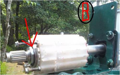
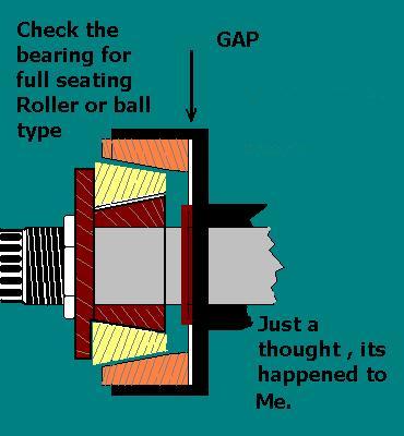
I'm not familiar with the hub you are using, bearing type,or method of securing it in place. Some use snap rings to locate the bearing, usually ball type, the common way is to machine a diameter in the hub that is a close fit to the bearing size, When the proper depth has been reached to match the width of the Bearing. the Machining stops, This is where the Bearing stops when it is pressed in, Or tapped in. The Gap in my Pic. is this
place. If a shim is needed, you will have to remove the
bearing from the shaft and install it first.
Your shim should only contact the inside diameter portion of the bearing.
Edited by Greenbelt 2009-07-19Time has proven that I am blind to the Obvious, some of the above may be True?
floodrod Regular Member Joined: 08/07/2009 Location: Posts: 70
Posted: 06:37pm 17 Jul 2009
Copy link to clipboard
Print this post
Hmm. I'll have to tinker with it. Guess I will cross that bridge a little later.
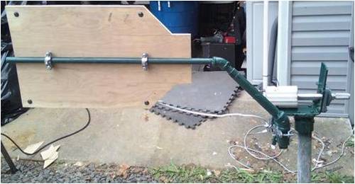
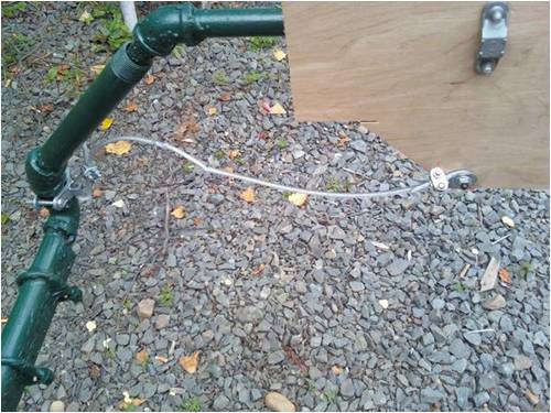
Today I started working on completing the furling and the tail piece.
I attached a guy wire cable onto cold water clamps to act as the "furling stopper" (for lack of a better word). It also discourages the tail from sliding too far out of the pivot pipe.
Here is a view of the tail in full furled position. If it goes past this point, the whole contraption will turn on the ya bearing
I will paint the tail probably white.
Hope this furling will do the trick.
floodrod Regular Member Joined: 08/07/2009 Location: Posts: 70
Posted: 02:27pm 18 Jul 2009
Copy link to clipboard
Print this post
OK, so I spoke to Randy (supplier of the F&P and the bearing) and we discussed the binding issue with the end nut. Since the bearings can't be moved or adjusted without machining, I must either use some permatex on the threads and not tighten it all the way, or my idea is to dremel a tad off the shaft blocking ridge. I just have to find a way to give the bearings a little more room.
So, last night I worked on the Stator. I have a new 36 Pole F&P, so I wired it in the star configuration. But I followed Randy's guide and used a ground wire across all common tie-togethers.
I used 8 gauge wire and two soldering irons.came out a little sloppy (like everything I do obviously), but every connection was made strong and I hot-glued it all in place.
When I hand-spin it, I see AC voltage coming out. Hard to get numbers hand spinning, but I say upto 18 Volts coming out between poles.
Tinker Guru Joined: 07/11/2007 Location: AustraliaPosts: 1904
Posted: 02:35pm 18 Jul 2009
Copy link to clipboard
Print this post
The outer rings of the bearings are held by friction fit on the aluminium housing embedded inside the plastic.
The shaft has a slightly bigger diameter than the bearing inner between the bearings, preventing them from moving too close together.
I usually use the shaft to gently tap the bearings out. Remove the nut completely and use a plastic or copper hammer to avoid bruising the shaft end. The far bearing will come out first, you then have to re insert the shaft and tap the opposite bearing out.
I am surprised you have not removed the bearings already, they are often in a bad shape from their washing machine use.Klaus
floodrod Regular Member Joined: 08/07/2009 Location: Posts: 70
Posted: 02:55pm 18 Jul 2009
Copy link to clipboard
Print this post
Well, Randy sold me the bearings inserted into the housing, so I assume he sold me good bearings:)
There's plenty of threads when the nut is tight. Maybe I will try to find a second nut and lock both nuts together with permatex#2 while leaving enough room for the bearing to spin freely. But finding that nut locally may be difficult.
GWatPE Senior Member Joined: 01/09/2006 Location: AustraliaPosts: 2127
Posted: 11:30pm 18 Jul 2009
Copy link to clipboard
Print this post
There would be many of these locking nuts lying around. Someone who repairs, or rebuilds these washing machines should have some spare. Maybe the postman could help someone get one to you. They would not be much to post, and the social networking would get a boost as well.
Gordon.
become more energy aware
floodrod Regular Member Joined: 08/07/2009 Location: Posts: 70
Posted: 02:21am 21 Jul 2009
Copy link to clipboard
Print this post
I managed to find a nut at a hardware store, but it seems I may no longer need it. Today I ordered the new pivot of Randys for the F&P with shaft bearings installed. So I am going to strip the bearings off the junk piece and let the home-made pivot rust away till I find another use for it.


 Those pipe elbows are cast steel and the pipe is steel, this might need a special welding rod.