Notice. New forum software under development. It's going to miss a few functions and look a bit ugly for a while, but I'm working on it full time now as the old forum was too unstable. Couple days, all good. If you notice any issues, please contact me.
Chopperp Guru Joined: 03/01/2018 Location: AustraliaPosts: 1139
Posted: 09:02am 04 Aug 2026
Copy link to clipboard
Print this post
Hi Any tips on doing this. My previous attemps of using this type of board have been rarther messy. Using the thin wire & a fine soldering iron would be a start I suppose.
BrianChopperP
PhenixRising Guru Joined: 07/11/2023 Location: United KingdomPosts: 2084
Posted: 09:53am 04 Aug 2026
Copy link to clipboard
Print this post
I use the OK-Industries wrapping tool and at first, my results were mixed. The trick is in threading the stripped portion into the tool correctly; insert the wire in the end of the tool but you want it to come outside the barrel of the tool.
With a bit of practice it becomes easier. The YT tutorials that I came across didn't show this, they went straight to wrapping.
I don't use the built-in stripper because it can cut too deep.
I have all kinds of wire strippers, including the overrated/over-priced Knipex stuff but the only one that can be set, reliably, to not touch the conductor is the plier-stripper:
It you nick the conductor, you will have a break during wrapping.
The other end of the wrapping tool is used for unwrapping. I'm now becoming quite proficient
Chopperp Guru Joined: 03/01/2018 Location: AustraliaPosts: 1139
Posted: 11:11am 04 Aug 2026
Copy link to clipboard
Print this post
OK Thanks for that.ChopperP
dddns Guru Joined: 20/09/2024 Location: GermanyPosts: 916
Posted: 08:06pm 09 Aug 2026
Copy link to clipboard
Print this post
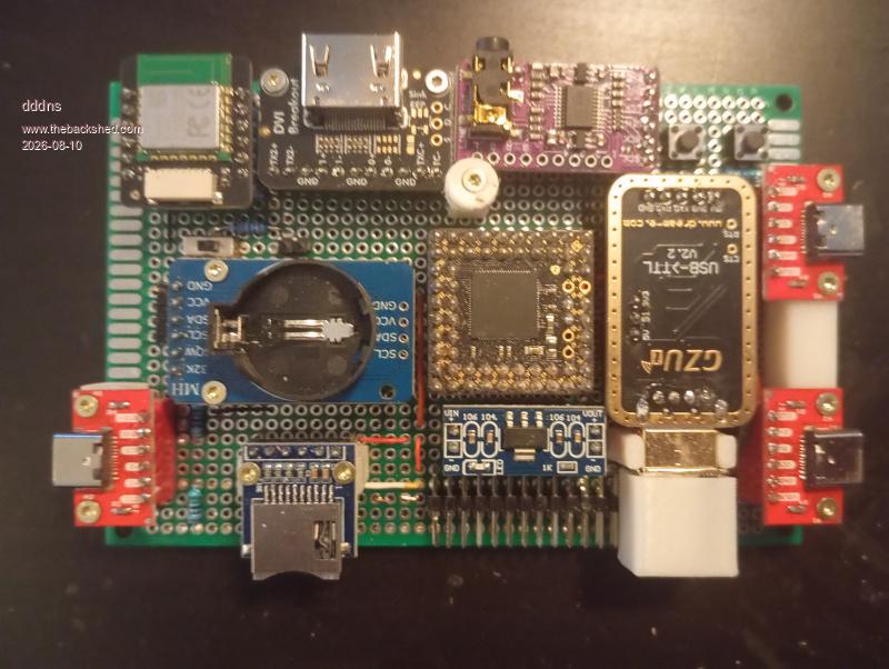
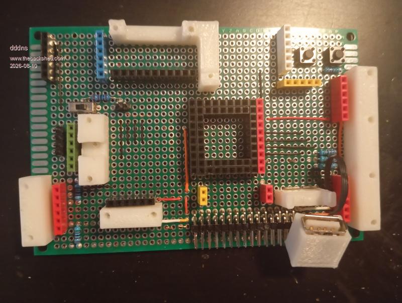
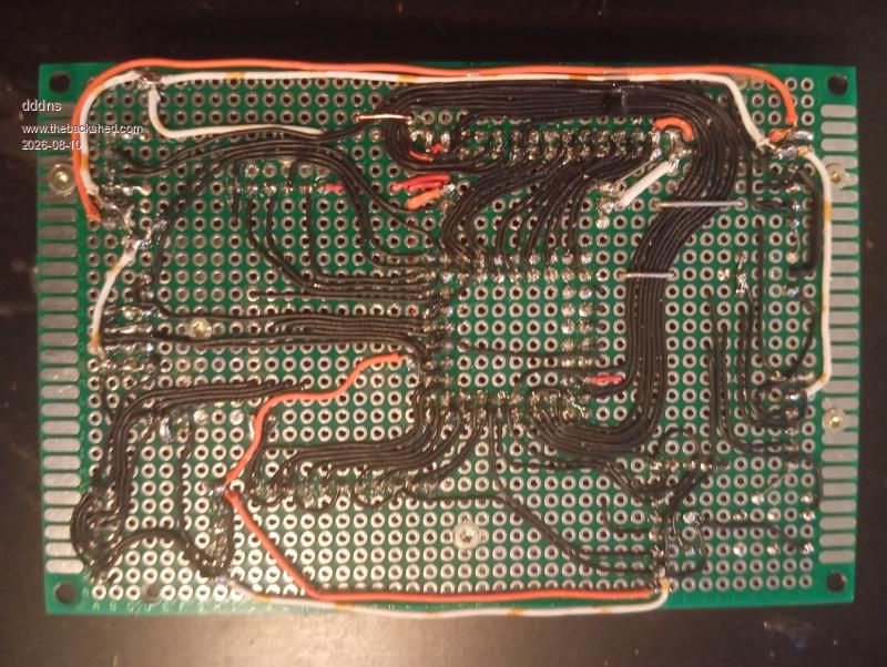
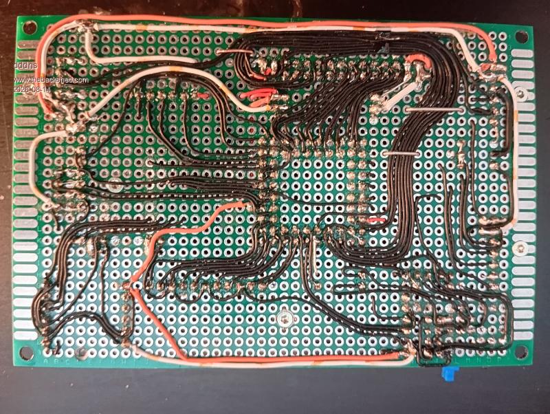
Good solder, patience, and the determination to keep working on a cable until it fits. I didn't quite follow that 100%, but it'll do for now. It looks okay under a magnifying glass.
EDNEDN Guru Joined: 18/02/2023 Location: United StatesPosts: 307
Posted: 03:08am 10 Aug 2026
Copy link to clipboard
Print this post
That is a very clean setup and wiring!!! I'm surprised you would able to make it so 'simple' and clean. There is hardly a single wire crossing another one.
Good job!!!
dddns Guru Joined: 20/09/2024 Location: GermanyPosts: 916
Posted: 05:52am 10 Aug 2026
Copy link to clipboard
Print this post
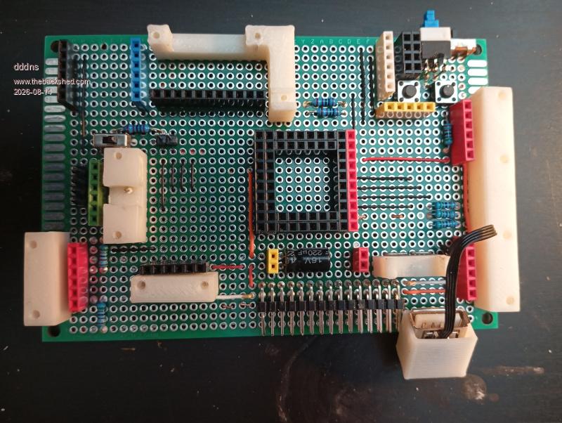
Thank you! Because of the two missing rows of pins, I had to make a few compromises, but otherwise I tried to route the traces exactly as they are in the KiCad layout to replicate the electrical conditions as closely as possible.
Regards
Edit: I'll post an update of the KiCad files once I've debugged it Edited 2026-08-10 15:53 by dddns
Mixtel90 Guru Joined: 05/10/2019 Location: United KingdomPosts: 9174
Posted: 07:56am 10 Aug 2026
Copy link to clipboard
Print this post
Very neat indeed! It's also nice to see someone else designing around modules. USB hubs are a problem, there are very few "breakout" modules around. The one I use isn't on 0.1" pitch so it's a bit awkward to use unless you are building on a PCB - and even then the footprint dimensions don't appear to be published anywhere.Mick
Chopperp Guru Joined: 03/01/2018 Location: AustraliaPosts: 1139
Posted: 11:24am 11 Aug 2026
Copy link to clipboard
Print this post
dddns
This something of what I envisaged. Good job. It did take me awhile to workout that you ran some of the wiring through vacant holes to the front side & then off eleswhere.
ThanksChopperP
dddns Guru Joined: 20/09/2024 Location: GermanyPosts: 916
Posted: 04:27pm 11 Aug 2026
Copy link to clipboard
Print this post
Hi Mick, and thank you. I think modules are a real alternative and not “ridiculous.” They’ve proven millions of times over that they work, are electrically self-contained, and come with a built-in 100nF capacitor—which saves time :) They also carry less risk compared to JLC, which sometimes delivers defective units—which would be a pretty big loss if one out of five were defective. I think the PGA is quickly checked before it leaves production. I still have a hub like the one you describe and I’d like to build a snap-on module.
Hi ChopperP, doing it this way with vias that have only a start and an end point is the best solution in every respect. This board is drilled with 1mm, it's very easy to thread the cable through
I wired the supply voltage with thicker wire. That might not have been necessary. There are various opinions online, but I’m leaning toward this one—my wire appears to be made of copper, and it tin-plates very well.
So, 30 AWG is: Outer diameter 0.635 mm Conductor diameter 0.254 mm Conductor cross-sectional area 0.051 mm² The internet says up to 1A is possible. Google it yourself :)
A 2mm copper strip on a PCB with a usual thickness of 0.035mm equals 0.07mm² Decide for yourself :)) Edited 2026-08-12 02:46 by dddns
Volhout Guru Joined: 05/03/2018 Location: NetherlandsPosts: 6168
Posted: 07:00pm 11 Aug 2026
Copy link to clipboard
Print this post
Only one remark:Peter uses a linear voltage regulator set to 1,3V for the 2350B core voltage to allow reliable overclocking. I am not sure if the 1.1V switching regulator inside the 2350PGA allows same overclocking.
You may be limitted in whar resolutions you can use.
dddns Guru Joined: 20/09/2024 Location: GermanyPosts: 916
Posted: 07:16pm 11 Aug 2026
Copy link to clipboard
Print this post
Hello Volhout, that's a really good point. Here's how I see it: I've had two PGAs since late 2024, and they've been through almost all the betas starting with 5.08. It turns out that my PGAs work very reliably up to 384 MHz, and in the winter, they can even go higher :)
At 378MHz they run super stable and that makes me think it could work. I hope tomorrow I can say more..
Regards Edited 2026-08-12 05:18 by dddns
Mixtel90 Guru Joined: 05/10/2019 Location: United KingdomPosts: 9174
Posted: 08:58pm 11 Aug 2026
Copy link to clipboard
Print this post
The PGA uses a LDO linear regulator. NCP115AMX330TCG according to the circuit diagram.Mick
javavi Guru Joined: 01/10/2023 Location: UkrainePosts: 615
Posted: 03:36pm 12 Aug 2026
Copy link to clipboard
Print this post
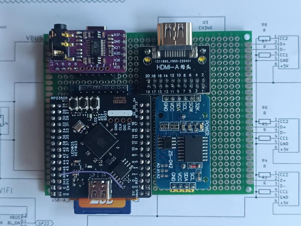
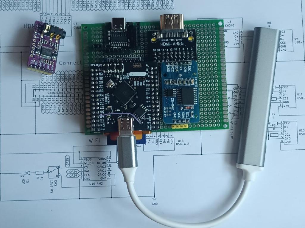
Hello everyone! I also decided to build a Pico Computer 3 on a breadboard. So far, I've compactly arranged the existing modules on the breadboard, except for the Wi-Fi radio module. The USB hub will connect directly to the USB-C port of the RP2350 module.
Mixtel90 Guru Joined: 05/10/2019 Location: United KingdomPosts: 9174
Posted: 03:48pm 12 Aug 2026
Copy link to clipboard
Print this post
Does that HDMI module include the necessary resistors? How have you hidden the USB-TTL converter to power it and give a console connection on GP8/GP9 while you are running it in USB host mode? . Edited 2026-08-13 01:53 by Mixtel90Mick
javavi Guru Joined: 01/10/2023 Location: UkrainePosts: 615
Posted: 03:53pm 12 Aug 2026
Copy link to clipboard
Print this post
@Mixtel90 Hi Mick, This HDMI module doesn't have any additional components, just direct contacts. So I'll be soldering the resistors to the bottom of the board. The USB-TTL serial port is hidden underneath the sound module. The SD card module is also hidden underneath the RP2350 module. Edited 2026-08-13 01:55 by javavi
Mixtel90 Guru Joined: 05/10/2019 Location: United KingdomPosts: 9174
javavi Guru Joined: 01/10/2023 Location: UkrainePosts: 615
Posted: 04:05pm 12 Aug 2026
Copy link to clipboard
Print this post
@Mixtel90 I'll be using this externally connected USB hub. I've used it before when working with PicoMite USB firmware. Now comes the long and painstaking soldering of each wire :( Edited 2026-08-13 02:10 by javavi
Mixtel90 Guru Joined: 05/10/2019 Location: United KingdomPosts: 9174
Posted: 04:19pm 12 Aug 2026
Copy link to clipboard
Print this post
I don't regard an external hub as cheating. :) I do think the Adafruit HDMI module is a neater approach though. Mind you, that's only if you happen to have one...Mick
dddns Guru Joined: 20/09/2024 Location: GermanyPosts: 916
Posted: 08:16pm 13 Aug 2026
Copy link to clipboard
Print this post
Hi Javavi, I like compact designs, and yours looks promising. Please post a few pictures once you’ve made more progress with the wiring.
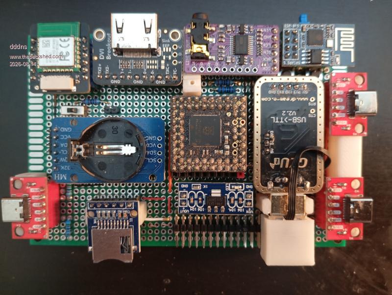
I planned to make my design pin- and chip-compatible with the original. Hopefully that’s the case, but there’s also the EEPROM on the DS3231 module and now an ESP01S as well. A transparent TCP-SERIAL bridge is running or is supposed to run on the ESP8266. On my Linux computer, I’m running ser2net, which creates a virtual serial port that can then be accessed by, for example, PuTTY or XMODEM.
But that’s just one option for me to experiment with; I have a switch to conveniently toggle between USB UART and ESP, and another one to disconnect the ESP’s power supply.
I’m also thinking that the ESP, in station mode, could act as the Access point for the RM2. That would bring us even closer to the concept of an autonomous system.
I’m not entirely sure yet… but it worked out and was perfectly routable. Here’s the final prototype for now, and I’ll post again if it’s up and running :)
lizby Guru Joined: 17/05/2016 Location: United StatesPosts: 3884
Posted: 12:07pm 14 Aug 2026
Copy link to clipboard
Print this post
@javavi -- nice work. Exactly which modules are you using (and what USB hub is that)?
Any reason not to have used the Adafruit DVI module, or the Aliex DVI "sock"?

 Notice. New forum software under development. It's going to miss a few functions and look a bit ugly for a while, but I'm working on it full time now as the old forum was too unstable. Couple days, all good. If you notice any issues, please contact me.


 Print this post