
|
|
Forum Index : Windmills : The MPPT Project.
| Author | Message | ||||
| Warpspeed Guru Joined: 09/08/2007 Location: AustraliaPosts: 4406 |
Ah! so you are using the boost topology. Many of the guys here are using F&P machines, and an excess of voltage is usually the problem, hence my suggestion of the voltage reducing buck converter. Gross non linearity in any feedback system is an absolute curse and can cause all manner of stability problems. The obvious solution is a feed forward system (instead of feedback) with some self learning capability. That would have instant response to sudden wind speed variations and no instability. Cheers, ĀTony. |
||||
| Gizmo Admin Group Joined: 05/06/2004 Location: AustraliaPosts: 5182 |
Wow, this thread took off! Kiwijohn, the boost in current from the inductor buck inverter is a bit like using a step down transformer. As an example, a trusty old battery charger, it can have a transformer that converts 240VAC 0.5 amps down to 12 volts 10 amps ( 240vac X 0.5 amps = 120VA, 12vac X 10 amps = 120VA ). So if our F&P windmill is making 50 volts at 2 amps, we can convert that to 14 volts at 7.1 amps, give or take. The smarts in a MPPT find the best conversion, to make the most of our available windmill power. Glenn The best time to plant a tree was twenty years ago, the second best time is right now. JAQ |
||||
| Gizmo Admin Group Joined: 05/06/2004 Location: AustraliaPosts: 5182 |
OK did some work on the software approach. Using a little PicAxe 08M chip, about $5. Pin 5 ( PWM Output 2 ) is sent to the Mosfet drive circuit, Pin 6 ( ADC input 1 ) connects to the Hall Sensor, then we just add power and the RS232 interface. Using command pwmout... pwmout Pin, Period, Duty PWM runs in the background so will continue to run while we process the other lines of code. Using the PicAxe wizard, frequence of 16kHz will give pwmout 2, 62, 250 = 1600hz at 100% duty cycle, effectively full on. pwmout 2, 62, 125 = 1600hz at 50% duty cycle pwmout 2, 62, 0 = 1600hz at 0% duty cycle, effectively full off. So we can vary the duty cycle from 0 to 100 in 250 steps, assigned to one integer variable called "PulseWidth". command readadc10 = 1024 steps of resolution, 0 to 5 volts. 0 amps is about 2.5 volts, or 512 internally. Hope all this is making sense. Now this code should work, may need a little bug removal.... Symbol Amp = W0 Symbol AmpOld = W1 Symbol NoAmps = W2 Symbol PulseWidth = b7 pmwout 2, 62, 0 "Make sure PWM if off, Mosfet off, so NO current should be flowing." readadc10 1, NoAmps "Read a base line from the hall sensor, our 0 amps value." NoAmps=NoAmps+5 "Add a margin of error." PulseWidth=5 "Set a base line PulseWidth" Main: sleep 1 "sleep for 2.5 seconds" readadc10 1,Amp "read the Hall sensor" if AMP < NoAmps then ShutDown "No windmill current, take a short break" if Amp > OldAmp then IncPulse "Amps increasing, try increasing the Pulse Width" if Amp = OldAmp then IncPulse "Amps steady, try increasing the Pulse Width" if Amp < OldAmp then DecPulse "Amps decreasing, try backing off the Pulse Width" got main ShutDown: pmwout 2, 62, 0 "shut down the PWM / Mosfet" PulseWidth = 5 "Set a low base line for when we come back online" sleep 4 "Sleep for about 10 seconds" goto Main IncPulse: PulseWidth = PulseWidth + 1 gosub UpdatePWM goto Main DecPulse: PluseWidth = PulseWidth - 1 gosub UpdatePWM Goto Main UpdatePWM: pmwout 2, 62, PulseWidth PulseWidth=PulseWidth min 0 "stop the integer going round to 255 ( 0-1=255, its a code thing )" PulseWidth=PulseWidth max 250 "as above, 250 is max for our PWM and 255+1=0" AmpOld=Amp "record the old amp reading" return Its a start. Basically it should hunt for the best current, and shut down when there is no current for 10 seconds. We still have 2 spare I/O pins we can use as well as the serial feed back to a computer if we want to log things. Glenn The best time to plant a tree was twenty years ago, the second best time is right now. JAQ |
||||
| GWatPE Senior Member Joined: 01/09/2006 Location: AustraliaPosts: 2127 |
Hi Gizmo, If you require a reduction in voltage from 160V > 24V, this would equate to a PWM duty cycle of around 24/160*100 as a %. = 15% or 38 out of 255 of the 8-bit output of the micro. This would be at maximum power, so the Mosfet would have to pass all of the power in that 15% of the time. The efficiency will drop as the power level increases and hence thermal runaway could occur at the high power levels. consider the implications of trying to current limit. If you try and reduce the pulse width, then the generator unloads and you have to rely on secondary protection. If you increase pulse width then the electronics will load the generator more and hopefully slow the rotor and reduce total output power. The cct mosfet will need to survive higher currents to do this. My experience has shown that before you MPPT you need to ensure the secondary and tertiary generator protection measures are working. I am not sure if the 8 bit output will allow sufficient PWM control to MPPT. The analogue version does not suffer this limitation. something to think about! cheers, Gordon. become more energy aware |
||||
| FandPwithPVC Regular Member Joined: 09/09/2006 Location: Posts: 64 |
Hi All I Have been trying to follow this somewhat complicated MPPT thing on this site. Not being gifted in electronics we have come up with a very simple,cheap and easy way to overcome output problems with F and P. We were told by some " Gurus" that our proposed ideas have been tried many times and they would not work. THEY ARE HOPELESSLY WRONG AS OUR METHOD WORK PERFECTLY It is very easy to knock an idea if it is not your own. The results we are getting are well above what we thought The ELECTRONICS you require are NON POLARIZED CONDENSERS such as you will find on fluro lights, large halogen lights and 240/415 volt motors and suchlike. These are readily available at scrap metal yards and you will need a total of about 450 MFD . Group these in 3 lots to form strings or lots of about 150 MFD.Join these strings together to form a continuous circle. The output from each of your F and P coils joins where the strings join each other.In bench testing we noted the Amp loading on our 1/2 HP motor. The wind mill we used is our 5 blade Piggott driving a 80SP in Star into 24 Volts. We can,t measure RPM from our tower and our mill will not achieve anything like 930 RPM THE RESULTS 193 RPM No Caps No Amps 182 RPM With Caps 4.5 Amps @ 26.5 Volts 240 RPM No Caps No Amps 239 RPM With Caps 4.8 Amps @ 26.8 Volts We should have discharged our batteries as we found as voltages rose Amps dropped. 346 RPM No Caps 3.0 Amps @ 27.2 Volts 306 RPM With Caps 8.0 Amps @ 28.4 Volts This is about as much as we could expect from our 1/2 HP motor with the mill being capable of much more. With a 1arger electric motor we continued 930 RPM No Caps 9.0 Amps @ 29.5 Volts 910 RPM With Caps 15.0 Amps @ 30.0 Volts At this stage our charge controller was going ballistic Conclusion Give the above a try and you will be well pleased with the results and the changes in the way your F and P performs Kind Regards Dennis L |
||||
| vasi Guru Joined: 23/03/2007 Location: RomaniaPosts: 1697 |
And this thread just received a massive blast 
I am afraid Dennis is right so here can be two teams. One to try Dennis solution and another to continue this way. Hobbit name: Togo Toadfoot of Frogmorton Elvish name: Mablung Miriel Beyound Arduino Lang |
||||
herbnz Senior Member Joined: 18/02/2007 Location: New ZealandPosts: 258 |
Right Vasi I dont want to see the progress we are builting up stopped. I have at home a capacitor bank 3 phase with 7 stages of 10 mfd caps ie total 7*3*10=210 mfd total I have used this before on FP generators both smart drive and gentle annie. I have a test rig on my lathe that I use for testing that uses a torque measurement to measure input power, output I feed into my battery bank that actually is driving the lathe. This gives me a full handle on what is going on eff wise and characteristic wise. I will re do some testing to refresh my memory on the effect of caps and find enough extra cap to come to Dennis's value ( I read into your message they are connected Delta 150mfd / phase ). Looking back at my results, that were more aimed at testing current limits, the caps do signifigantly change the output chac's more caps more output but also more input power eff about same What alters is the machine takes on a different characteristic. as if you had altered the windings or increased the rpm. I have the luxury here of having hydro units that are steady state output, putting caps on these does not change output only rpm they operate at. You can sometimes get small gains by hitting a sweet spot. This is not in my mind another control method but a generater design consideration. Please dont stop work on MPPT. I will set up tests Dennis and look at this the change is because the stator flux and rotor flux in a normal machine get out of alignment because inductance, caps pull this back but old story never get any thing for nothing. Herb |
||||
| herbnz Senior Member Joined: 18/02/2007 Location: New ZealandPosts: 258 |
Tony The output most people see from FP's is battery volts as the battery ties down the output volts but off load they can go very high. With the controller we will need some over ride that will clamp this i see most pwm chips have a extra input for this situation. It would be a saving to be able to use the FP in a nearly standard winding I can test to see what configerations will give voltages that dont exceed say 150 volts on open cct. Also back to inductors is one possible solution buy cores and wind our own ( something to do sitting in front tele ) I for one would purchase at the price you have tho remember the price commercial Mppt's Herb |
||||
| Warpspeed Guru Joined: 09/08/2007 Location: AustraliaPosts: 4406 |
Wow this is all becoming really fascinating, first of all just looking at the wind machine itself, there seem to be three distinctly different paths to follow. Use a machine that has an output voltage that is about right to charge the battery at higher wind speeds. Then use a voltage boost converter to increase the machines output voltage at low wind speeds. This would then start charging well below the normal cut in speed. That is the approach Gordon has taken. The alternative is to have a much higher voltage rated machine than the battery voltage, (such as an F&P). This is going to easily have enough voltage to charge at low wind speeds, but at higher wind speeds the output voltage needs to be reduced with a buck converter to reduce the mechanical loading on the machine to allow better blade efficiency. Which is going to be more suitable depends on the relative output voltages of the machine and the battery. Simple buck or boost converters either reduce or increase the voltage, they can do either one or the other, but not both. The third method is extremely interesting. It appears that capacitively tuning the windings of a multi pole machine causes a buildup of resonant energy within the windings. This resonant energy probably drives the iron in the pole pieces into and out of hard magnetic saturation, regulating the output voltage to some maximum. This ferroresonant effect should also significantly increase the available output voltage at low rpm, provided the windings are appropriately tuned to the lower operating rpm range. This is a truly brilliant idea and is well worth some further development. This principle is not new, but is the basis of the ferro resonant constant voltage transformer. Here is an explanation of ferroresonance: http://www.cadickcorp.com/tech004.htm But getting back to MPPT controllers. In the voltage boost topology the negative of the wind machine connects straight through to the negative of the battery. This is extremely convenient, because it allows the current to be monitored with a ground referenced current shunt in the negative side of the circuit. With the buck topology, it is the positive side of the circuit that connects straight through from wind machine to battery. This rather complicates current measurement. The most trouble free way to do this is probably to use a linear Hall effect current sensor as shown in the circuit diagram in an earlier post. The actual "brains" of the MPPT control system could be either built analog, or written in software, there are a whole mountain of advantages and disadvantages to using either method. Cheers, ĀTony. |
||||
| GWatPE Senior Member Joined: 01/09/2006 Location: AustraliaPosts: 2127 |
Hi Tony, The last thing we non engineers want to do is let the smoke out of our MPPT or have a mill self destruct. The main advantage of having the maximum mill output matched to the battery voltage is that of safety. Ideally at maximum output the electronics have turned OFF and only the rectifiers are in the DC path. No switching devices need to operate. This means that the electronics can be easily sized to suit the generator output and the battery voltage. The F&P S/P rewinding is not too difficult. The boost topology would kick in at a low power. As the power level increases, then the modulator backs OFF and the cct eventually does no work at peak output. The cct only has to process the difference in voltage between the generator and the battery voltage. As the generator increases rpm with increasing wind speed the task becomes easier. Buck cct are used with solar panels so the panel reverse voltage is always greater than the battery and reduces the need for blocking diodes. A mill will have a recftifier anyway. I havn't seen any synchronous rectifiers on offer yet. With the buck cct, as the power increases, the cct has to convert a higher voltage difference and the current will increase. The power increases in the cubic relationship. Towards the maximum power, a gust of wind can easily double the power the cct has to process. My experience has seen the bridge rectifier surviving the peak power that has fried windings. I would think the approach of a parallel resonant cct on the windings before the rectifier with a voltage boosted low end could be achieved with micro control. I know a lot of older style F&P stators are out there, but a retro-fit with a 60 or 80 SP stator would probably be most mill owners best bet. some more to think about! cheers, Gordon. become more energy aware |
||||
| Warpspeed Guru Joined: 09/08/2007 Location: AustraliaPosts: 4406 |
I agree with most of what you say Gordon, but I am not so certain about the superior efficiency. High voltage and low current is going to have lower losses everywhere except arguably right at the point of conversion down to the lower voltage. That may conveniently be done right near the battery for lowest overall loss. The difference could be significant if the wind machine and battery are a fair distance apart. It is not just the theoretical losses right at the MPPT conversion stage, but rectifier and wiring losses need to be figured into the whole thing as well. A twelve volt wind machine may have significant wiring and rectifier drops when charging a twelve volt battery at high current. By keeping the voltage much higher coming into the MPPT, my argument is that overall efficiency could be greater, even though the buck converter efficiency is theoretically less with high transmitted power. Cheers, ĀTony. |
||||
| GWatPE Senior Member Joined: 01/09/2006 Location: AustraliaPosts: 2127 |
Hi Tony, I have never been a fan of 12V systems either. I have a 24V system. I built my own schottky rectifier for my 4 phase mill. All SMD and no heatsinks. My MPPT uses a SMD schottkey diode and the single swithing mosfet is SMD with no heatsink. [160A @ 60V Jaycar] cct must be efficient if nothing produces heat. Wiring loss is related to conductor size and amps. My mill is quiet, so is on a pole attached to the house. Boost cct is under the eave. All wiring is effectively at 24V battery potential. 6mm orange circular is adequate. If you wire to the maximum current then the average wiring losses are insignificant anyway. Wire can be obtained cheaply from wire recyclers. time to stoke the fire. cheers, Gordon. become more energy aware |
||||
| Warpspeed Guru Joined: 09/08/2007 Location: AustraliaPosts: 4406 |
Gizmo, I have been giving some more thought to how best to use a microcontroller to control the MPPT. Gordon obviously is very experienced in all this, and he has raised several important issues concerning the difficulties of implementing closed loop feedback. So how about a feed forwards system instead? This could be done by measuring wind speed quite independently of the main wind machine with some sort of anemometer. The output of this anemometer should respond very fast in gusty conditions, probably faster than the main rotor. The output of the anemometer could then go into into an a/d and, the wind speed value access a software lookup table where suitable preset PWM values are stored. This lookup table could be fairly coarse, maybe eight PWM values for eight ranges of wind speed may be enough. It would be like having eight rotor tappings that shift up and down virtually instantaneously with changing wind speed. Each lookup table can be optimized to suit the characteristics of each individual machine. Here is the concept in hardware, but it could also be done in software. 
A hardware version could use multiple trim potentiometers and an analog multiplexer. A row of LEDs could indicate which trim pot is active at any particular wind speed. Each pot can then be tweaked for optimum PWM duty cycle to give maximum peak output power. The beauty of feed forward is that it is incredibly fast acting, and has zero chance of any instability. Cheers, ĀTony. |
||||
| herbnz Senior Member Joined: 18/02/2007 Location: New ZealandPosts: 258 |
Hi I would see the anemometer feeding a differentator cct that was a cap in series resistor the voltage across the resistor would reflect the change and could step the control cct in advance Herb |
||||
| Warpspeed Guru Joined: 09/08/2007 Location: AustraliaPosts: 4406 |
Gordon, I have now built and bench tested an experimental buck regulator, and made a lot of measurements and calculations over the last couple of days. You are absolutely right and I was wrong. The biggest difficulty is achieving reasonable efficiency at high power. All the significant circuit losses are resistive, and losses increase square law with current increase. That means everything needs to be specified vastly over sized to not become excessively hot. So an optimum design appears to be exactly as you suggested. Configure the mill windings to work optimally at the highest expected wind speeds, and then use a PWM boost converter to artificially raise the voltage up to battery charging voltage at very low wind speeds. Glenn's staggered winding system does something fairly similar to this in a very ingenious way. The advantage of your boost converter approach, is that the PWM duty cycle would be infinitely adjustable, whereas there are only a certain number of combinations of staggered windings possible. Getting the best out of a particular set of blades and blade angles may be easier with continuously adjustable PWM, but the staggered winding idea is simple and truly brilliant !! Cheers, ĀTony. |
||||
| GWatPE Senior Member Joined: 01/09/2006 Location: AustraliaPosts: 2127 |
Hi Gizmo, I have answered my own question, re images. I have just included a pic of my mill. Not too much happening on this day. 
the next photo is output from the mill. voltage and amps with power included. 10 readings per second recording. about 7 mins in total. 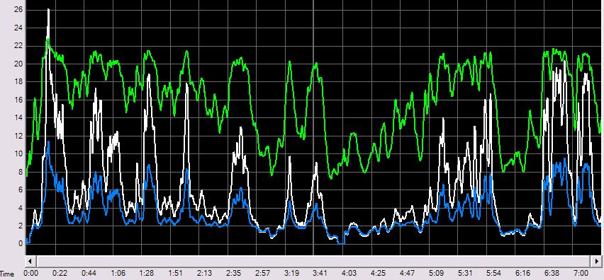
This is a typical average day output at my site Amps in blue, volts in green and power/10 in white. This is how my MPPT loads my mill. You will notice how the voltage and current vary with time. The mill rpm follows the windspeed. The electronics responds very rapidly to the changing power, increasing or decreasing. I have compared the windspeed log from my weather station and the gusts follow a linear up and down in windspeed, while the power output follows the cubic relationship. This is what you would expect from a true MPPT. The F&P mill with MPPT will respond slightly differently to my mill with a MPPT. Warpspeed uses the feed forward expression. I would call the control process I use as direct control. The generator voltage directly controls the loading of my mill using a variable current limiting process. There is no feedback control, negative, or positive. The sensing element is the voltage controlled shunt in the battery negative. No hall effects used, and all DC coupled to the modulator summing junction. This approach was my electronic conclusion to a voltage controlled relay arrangement that bank switched my 4 rectified and filtered phases out from 4s to 2s x 2p to 4p as the windspeed increased. the click clack of relays up on the tower was frustrating and power wasting, with no semiconductor option. I hope the discussion continues, so that the MPPT with F&P can be concluded. cheers, Gordon. become more energy aware |
||||
| sPuDd Senior Member Joined: 10/07/2007 Location: AustraliaPosts: 251 |
Warpspeed, The config of your Buck in the block diagram early on in this thread is quite neat. It solves the problem I had with having to use massive expensive transistors in the output switching stage. Now I can use massive cheap MOSFETS. 
Although the PSU/s I'm building are mostly for bench work, I need to adapt a robust system for MPPT work on wind gens as well. On the subject of this thread, I've had good results with old PC PSU E-cores. The PSU itself also yields good cheap heatsinks, Schottky diodes, etc. I'm a fan of the TL494 PWM IC, its cheap, easy and abundant. And like Gizmo I'm also a fan of the PICAXE. The latest units have caused drool problems with my keyboard 
sPuDd.. It should work ...in theory |
||||
| nweeks Newbie Joined: 22/01/2007 Location: AustraliaPosts: 36 |
Hi All, months ago, I quickly fleshed out the pseudo code for a PicAXE MPPT controller. I've subsequently come up with a better one that only samples voltage, and doesn't need to measure the current, but I'm just trying to find that one. May / may not be helpful! :-) http://prism9.com/resources/mppt_v1.txt Enjoy! Nige. Nigel Weeks nweeks at karbonit dot com |
||||
| nweeks Newbie Joined: 22/01/2007 Location: AustraliaPosts: 36 |
Found the simpler one, and put it up: http://prism9.com/resources/mppt_v2.txt Once again, just an idea... Nige Nigel Weeks nweeks at karbonit dot com |
||||
| Warpspeed Guru Joined: 09/08/2007 Location: AustraliaPosts: 4406 |
Some further thoughts on all this. From what I can see, there appear to be three main obstacles associated with matching any wind machine to the task of charging a battery with an MPPT. The first is the variation of available rpm and shaft output torque from the turbine with wind speed. That will be highly dependent on the diameter, number, and pitch of the blades. Second, the output voltage and current of the generator (or alternator) needs to reasonably match the available mechanical output power of the wind turbine. Any particular electrical machine may approximate a stiff voltage source, or a high impedance current source, or more likely something in between. Every electrical machine will have it's own unique characteristic of variation between mechanical rpm and torque input and electrical output in volts and amps. Thirdly, wind speed can be highly changeable, and the available electrical output power will be grossly non linear because of the above three factors combined. In any feedback system the amount of correction that is fed back to the input, and the rate of allowable change are extremely important. If the amount of feedback correction applied is insufficient, there will not be enough correction applied to hold the output steady, and the system will not control very well. If too much feedback is applied, or is applied to quickly, the system output will over correct, and swing in the opposite direction. That can send the system into unstable oscillation, where the over corrected output variation is then fed back, reinforcing the input variation, and the output then begins to swing wildly back and forth with ever increasing amplitude. Where a system being controlled is completely linear, how much, and how quickly corrections can be fed back to control the output can be fairly easily established, and the system will work fine. But a hugely non linear system can present some real problems. At some point in the operating characteristic, feedback will be less than required, and the output cannot be controlled sufficiently well. At another operating point the system may suddenly become unstable. An MPPT system may be practical using feedback, but it may have to respond very gradually in order to remain stable over a wide non linear operating range. That may not work terribly well in gusty conditions. Feedback systems can be very practical, but in some situations they simply cannot be made to work well enough to be useful. Here is where the feed forward system can usefully be applied. A good example of a classic feed forward system is an automotive engine management unit. Engine speed and engine load is measured, and the amount of fuel fed in is referenced from an internal lookup table or "map". When you suddenly mash your foot to the floor, or instantly back off to change gear, the amount of fuel fed into the engine instantly changes. There is no attempt to measure what comes out of the exhaust pipe and constantly "correct" the fuel flow with some feedback system. It would simply be far too slow. So what any engine management unit does, it measure all the possible range of inputs to the system and figures out what the instantaneous fuel flow should be. All these inputs are then "fed forward" to control the fuel flow directly, instantly, and painlessly. The fuel output quantity may be wrong, if the engine is not tuned well, but it will always respond fast, and it can never become unstable because nothing is "fed back". So here is the clue. An very basic engine management unit typically looks at three inputs: Engine speed Engine load (throttle position) Engine temperature And directly produces two highly non linear outputs, from these inputs: Fuel volume Ignition timing Because there are three inputs, a three dimensional map is required to store every possible combination of the three input variables. Getting back to controlling a wind machine, we have only one input variable: Wind speed And one output variable: Pulse width modulation duty cycle. So all a feed forward system needs to do is store a suitably ifferent PWM value for every possible wind speed. The turbine blades, and generator can have any sort of weird non linear relationship, but for every extra knot of wind speed, there will be an optimum PWM value, and that value can be stored in a lookup table. That Is what I was suggesting earlier, by using an anemometer to measure instantaneous wind speed, and using that to control the MPPT in a fast responding feed forward system. Turbine rpm, generator voltage or generator current cannot be used as feed forward inputs, because all will change with electrical load. You absolutely MUST measure the true original raw system input variable for feed forward, which for us is simply wind speed. Just like an engine management unit, it will be extremely fast responding and unconditionally stable, but it will need some manual "tuning" initially. Cheers, ĀTony. |
||||
| The Back Shed's forum code is written, and hosted, in Australia. | © JAQ Software 2026 |
