
|
|
Forum Index : Windmills : DOUBLING FISHER an PAYKEL OUTPUT
| Author | Message | ||||
| vasi Guru Joined: 23/03/2007 Location: RomaniaPosts: 1697 |
If they have Total Commander (the best file manager for Windows - like old Norton Commander), no problems. Total Commander can handle rar files (but not multivolume). This program is a "must have" on every computer. Hobbit name: Togo Toadfoot of Frogmorton Elvish name: Mablung Miriel Beyound Arduino Lang |
||||
| FandPwithPVC Regular Member Joined: 09/09/2006 Location: Posts: 64 |
Hi All This topic is drifting well away from DOUBLING FISHER AND PAYKEL OUTPUT.Dr Chalko ? and now Total Commander ? We have had absolutely no heating or warming problems with capaciters. We do however when testing newer ways protect ourselves from the possibility of them exploding . Our battery bank comprises 4 large 12 volters giving us a 24 volts load. The chances of overcharging is a problem and we are redesigning our dump load.The bridge rectifiers do get hot and we are working on this also. The F and Ps get slightly warm but never hot. With more tower and mill testing 143uF by 240 Vac caps are the best at all speeds. As speeds increase voltage doubling drops off although raising 18 Amps to 24 Amps at 412 RPM is still very worthwhile All for now Dennis L |
||||
| vasi Guru Joined: 23/03/2007 Location: RomaniaPosts: 1697 |
Sorry Dennis, for this discussion and exchanging files we need computers and software tools, you know that. Sorry for disturbing you. I'm watching this topic with much interest. Thank you for your details about caps. Hobbit name: Togo Toadfoot of Frogmorton Elvish name: Mablung Miriel Beyound Arduino Lang |
||||
| Gizmo Admin Group Joined: 05/06/2004 Location: AustraliaPosts: 5182 |
Thanks for zipping the document Mark. Anyone interrested should read the file Highlander has uploaded, it shows the early work done by Dr Tom Chalko on capacitors and the F&P. Here is a photo of his test rig taken from the document. 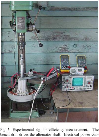
Glenn The best time to plant a tree was twenty years ago, the second best time is right now. JAQ |
||||
| GWatPE Senior Member Joined: 01/09/2006 Location: AustraliaPosts: 2127 |
I see the CRO output voltage waveform on the last pic and Digital RMS meters. Not a bad sine wave, not real good to try and put into a battery though. The only time current can flow is when mill volts > batt volts. If you are measuring RMS V and A then you are seriously under-estimating the real peak V & A. I can not begin to predict the outcome with cheaper metering. I also notice the use of a SparOmeter power meter. I have one of these. They under or over estimate depending on the power factor of the load. Has anyone looked at the current waveform with a CRO for a Cap v non Cap system into a battery. a bit of digression here--- The sine wave output problem is why I designed my mill gen to produce a close square wave output. I recall that early Southern Cross gen sets also produced a square wave output specific for charging a battery. Sine waves are produced by utilities primarily as they are easy to transform and introduce low harmonic content. Do the capacitors change the shape of the voltage waveform of the mill into a resistive load? If the sine waveform is flattened on the top and bottom then battery charging will be improved, as peak currents will be reduced, closer to the average. what has wrong with this thread? Is it me or are all the posts running over past the edge of the screen. A bit tiring with the mouse on the scroll bar. Gizmo, can it be fixed ?? cheers, Gordon. become more energy aware |
||||
| Gizmo Admin Group Joined: 05/06/2004 Location: AustraliaPosts: 5182 |
Its caused by large images, you can blame 9c12m for it  Sorry 9c12m, dont mean to pick on ya. Sorry 9c12m, dont mean to pick on ya.
Glenn The best time to plant a tree was twenty years ago, the second best time is right now. JAQ |
||||
| FandPwithPVC Regular Member Joined: 09/09/2006 Location: Posts: 64 |
HI All I would suggest the picture of Glens F and P in a drill press has not got caps on it. Therefore get a 80s F and P , do the standard rewire 80sp put the caps on exactly as shown and then criticize. Don,t forget you can get $100 if it does not double. We have done waveforms but it is too complicated for this post It would be more suited to the Technical MPPT post. Some more testing shows that the performance of the caps drops off at speed. At 412 RPM 18 Amps becomes 31 Amps after Caps. The output doubling occurs at about 300 rpm with 4Amps becoming 11 Amps . At 365 RPM 5.8 Amps becomes 13 Amps. Our current wind mill will not achieve 412 RPM due to wind turbulence and its 5 blades. 15 Amps is about its current limit All for now Dennis L |
||||
| GWatPE Senior Member Joined: 01/09/2006 Location: AustraliaPosts: 2127 |
Hi Dennis, to be fair on Gizmo, the photo was lifted from a research paper and is not his mill. The gen is another mod of a F&P, 100S with half of the stator fingers removed. This leaves 3 phases with 7 coils in series. My reading of the article would suggest that the 3.3uF caps across each phase and the 713rpm would equate to a cap > 100uF for an 80SP operating at half the rpm. The paper clearly concludes that power output can be expected to increase by as much as 200% with caps, but at the expense of generator efficiency. My conclusion is similar to gizmo, that caps change the characteristics of a mill, similar to rewiring, but simpler, but at the expense of causing a higher current to flow. The power densitity of the mill increases at the same rpm, but at the expense of a lower generator efficiency, as was stated in the article. The addition of caps will enable the mill to put out power earlier, but this will mean that the blade optimum operating relative wind angle will now change, as the mill will load more at the same rpm. were the rpm v amps quoted above from a mill in the wind or bench testing with a lathe etc? If the testing was on the bench, then a few more data sets would be useful, particularly in the 150-250rpm range. a preliminary plot shows very rapid loading with rpm. I can only assume that these are bench test data. An under driven mill would probably go into stall attempting to produce a higher output. After adding caps, blade retuning may be required. Who is building the wind tunnel? cheers, Gordon. become more energy aware |
||||
| FandPwithPVC Regular Member Joined: 09/09/2006 Location: Posts: 64 |
HI ALL We have now done some testing with a 100S in Delta. That is the thick wired one straight out of the washing machine. Cut the brass buzzbar and connect it all up in series. The caps connect across these. Dead simple and cheap. Like all this testing your props need sufficient torque to drive although at high speed it is not as important. At 170RPM we got 2.5 Amps and with caps it stalled. This was due to our bench test electric motor not being able to handle torque at a low speed. The wind mill does not have this problem. At 250 RPM we got 9.5 Amps and with caps 240RPM and 19 Amps This is excellent and is probably the " Sweet Spot " At 295RPM we got 16 Amps and with caps 280 RPM and 20 Amps. Over this speed both our test bench and the wind mill had difficulties driving it. It reaches its limit on the mill and that puts the brakes on for more. It may well be that the 100S is the better option ? All for now Dennis L |
||||
| GWatPE Senior Member Joined: 01/09/2006 Location: AustraliaPosts: 2127 |
Hi FandPwithPVC, here is the section from the conclusions on the last page of Dr Chalko's paper. 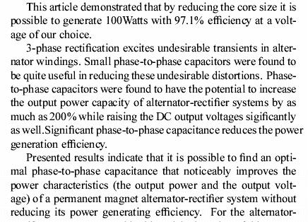
This was the confirmation of your experimental results from another source. cheers, Gordon. become more energy aware |
||||
| Jon Bennett Newbie Joined: 01/11/2007 Location: AustraliaPosts: 27 |
Hi Have read the thread so far and sounds like a good outcome but i have a few questions. What is the efficiency of a F&P alternator normaly, ie watts out as electricity / watts in as rotational energy? Where was the energy that is now being accessed as electricty being lost before the capacitors were fitted? Does the winding run noticibly cooler than without the capacitors? Thanks jon |
||||
| FandPwithPVC Regular Member Joined: 09/09/2006 Location: Posts: 64 |
Hi All .It is said that you do not get anything for nothing. All F and P motors and there various rewires suffer INHERITANT IRON FLUX LOSSES which means they are not very efficient as a generator. The trick has been to smooth out the way you make DC from AC which overcomes this. We are not as clever as some but after hundreds of trials we are EASILY OUTPUT DOUBLING There is NO EXTRA AMPS being required for our 240 Volt test motor to drive it and our windmills do not load or notice capaciters either. We though there had to be some losses and looked and looked but no there wasn,t. All our test so far indicate that changing Capaciters for each model of F and P are unnessesary and make no variation . The only heating problem we have had has been with our Bridge Rectifiers. As a further example of output doubling use a 80SP in star at at about 290 RPM to get 10 amps at 26 volts Put the caps on and it becomes 22 AMPS at 26 volts Build it first and then try and fault it without throwing theories at it All for now Dennis L |
||||
| Jon Bennett Newbie Joined: 01/11/2007 Location: AustraliaPosts: 27 |
Hi Dennis Wasn't having a go at you, haven't had any experience with F&P units or wind driven generators at all yet. Trying to work out what looks like it is the best way to go before I get started. Was actualy after the answers that you have provided. thanks jon |
||||
| GWatPE Senior Member Joined: 01/09/2006 Location: AustraliaPosts: 2127 |
Hi FandPwithPVC, As you know, I have participated with some of your experimenting on some of the F&P configurations. You will remember that I commented on the AC motor consuming almost the same current running with or without a generator connected. I feel that readers should know how much AC power was input to the motor and how much power was then supplied to the load during these tests. I know that the output current did double with capacitors added. I think that the test data did not fully record what happened during testing. I have come from a scientific background and know the difficulty in providing objective data for comparison. I think that before more comparison data is provided that you should consider testing using a much more efficient motor driving the generator. You should see an increase in input power for an increase in output power. Probably a DC permananent magnet motor. This should satisfy readers if an unloaded motor input power and then input power with and without capacitors with the corresponding power generated with an without capacitors. I believe that readers appear to be sceptical regarding the capacitor issue and that supporting test data needs to be well presented. PS.. the best motor to use would probably be a F&P. cheers Gordon. become more energy aware |
||||
herbnz Senior Member Joined: 18/02/2007 Location: New ZealandPosts: 258 |
Denis as i have explained before to accuratly measure input power arrange mounting of either motor or generator so iits housing is free to rotate stop this rotation with a spring balence then input power is able to be calculated exactly regardless of drive motors own losses. I have set up her and as promised will run accurate tests as time permits. One thought any interseted person want NZ holiday in remote location on beach and willing to carry out tests? herb |
||||
fillm Guru Joined: 10/02/2007 Location: AustraliaPosts: 730 |
Hi all, I have been watching this forum with intrest and would like to try the caps on my mill. What size do i need for 48v ?.. Ive just completed building 2 neo rotors to fit to my dual when I get home next week , on testing them here they have a 40 - 50% power increase I would also like to try the caps on these and see what happens , I have come accross 400Vac 50uF non polarised ,would these be suitable to try ?. At present I have 12 wires down to a rectifier box at the pole base where I switch star/delta I could put caps on one stator and measure the difference in performance of the same shaft. Would this be a viable test? Not being a electricial wizz I can only guess that with increased voltage 48v I would need larger caps than 12 or 24v or because of the decrease in amps would it be smaller caps ? Can the caps only be used in star not delta ? ... Phill... PhillM ...Oz Wind Engineering..Wind Turbine Kits 500W - 5000W ~ F&P Dual Kits ~ GOE222Blades- Voltage Control Parts ------- Tower kits |
||||
| FandPwithPVC Regular Member Joined: 09/09/2006 Location: Posts: 64 |
Hi All There are probably 100s of people in Aus with F and Ps on towers with some working better than others. Output doubling means increasing the output without increasing the input. WE ARE THERE. Most of us have 24 Volt systems with a variety of F and Ps and props. The better ones such as ours do not notice cogging but lack a little in speed.Five blade Piggott Like others they sit on about 18 volts in light winds and only rise to 26 volts with better winds. This means all this potential energy is wasted. With capaciters the 18 volts rises to about 36 volts unloaded. Being pegged back at 26 volts DC you will NOW GET AMPS where it wasn,t possible before. Regards Dennis L |
||||
| herbnz Senior Member Joined: 18/02/2007 Location: New ZealandPosts: 258 |
Hi Had my test rig set up today so decided to take up Dennis's figures with a 80sp stator. could not get output 290rpm had to go to 340rpm to get 2a charging into my battery bank. No Caps Watts in = 62 watts (Kgf =.6 ) Watts out = 50.8 (25.4v @ 2a ) Eff = 82% Caps Watts in = 314 watts ( Kgf = 3 ) Watts out = 243 watts (27.4 v @ 9a ) eff = 77% both tests the speed was set to 340 rpm the torque arm was .3 metre The cap was my switched Capacitance bank that switches 7 stages in 10 mfd steps per phase. At each of the steps a load increase was observed but readings were only taken at the No 7 step (210 mfd ) Adding capacitances has the effect of effectively increasing the turns per coil could be used to give switched staging on mills . One problem I see is need to connect them before rectifier and rectifier needs to be at the stator. Herb |
||||
| KiwiJohn Guru Joined: 01/12/2005 Location: New ZealandPosts: 691 |
Herb, that seems to be logical... I presume that without capacitors the inductive reactance limits the current flow which accounts for the low output. Adding capacitors introduces capacitive reactance that counteracts the inductive reactance somewhat but neither can reduce the simple resitance losses, not even considering what is happening in the way of magnetic/iron losses etc. I expect there is a value of capacitance that is optimum for every RPM, a point where inductive reactance equals capacitive reactance and will (I think) be unrelated to actual current drawn. It follows then that capacitors could be switched in according to RPM. |
||||
| herbnz Senior Member Joined: 18/02/2007 Location: New ZealandPosts: 258 |
Hi John It is a lagging current thing due to inductance the diodes are forward biased by voltage if the current is not there bad luck. as for values at different rpm (frequency) Xc is inversly proportional Frequency Xl directly related. Cheers Herb |
||||
| The Back Shed's forum code is written, and hosted, in Australia. | © JAQ Software 2026 |
