
|
|
Forum Index : Windmills : Neo conversion
| Author | Message | ||||
Gill Senior Member Joined: 11/11/2006 Location: AustraliaPosts: 669 |
Martin, Please EDIT your lateral placed pictures. This post is so pregnant it is hard to read. Only you as the creator or Glenn as the administrator can fix it. Provided you are logged in, go to the post causing the problem and only you will have an EDIT button showing at the end of the post because you made it. Press, then move the cursor between the image listings and press [Enter] to correct. Else delete everything if duplicated later. [imq]??????first??????.jpg[/img][imq]??????second??????.jpg[/img] -----------------------------^ ----------------------------here Thanks in anticipation was working fine... til the smoke got out. Cheers Gill _Cairns, FNQ |
||||
martinjsto Senior Member Joined: 09/10/2007 Location: AustraliaPosts: 149 |
thanks gill wasnt sure how to fix it, i will be carefull to enter after every pic posted from now on martin free power for all McAlinden WA |
||||
imsmooth Senior Member Joined: 07/02/2008 Location: United StatesPosts: 214 |
How hard is it to remove the rotor from around the stator once neo magnets are on it? I mounted some screws on the cradle to help rachet it off; I'm expecting it to be more difficult. Has anyone encountered any problems due to the increased magnet strength? |
||||
Tinbender Newbie Joined: 03/02/2008 Location: United StatesPosts: 14 |
Removed to appropriate thread. VAWTs Up Doc? VAWTs Happening? Is that VAWT you vant? VAWT vere you thinking? |
||||
| martinjsto Senior Member Joined: 09/10/2007 Location: AustraliaPosts: 149 |
you should be able to use the existing nut im not there yet so im not too sure i have finaly been able to get back to my neo mod after a short break for work 
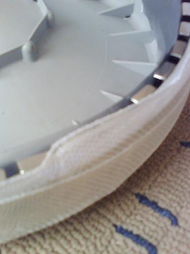
i found the old rubber used for retaining the flywire in flyscreens a good size for my mod 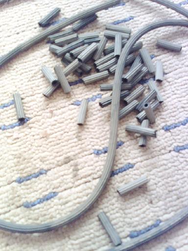
i then formed the dam using ducktape 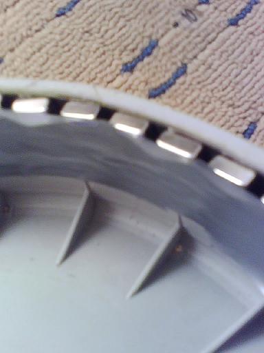
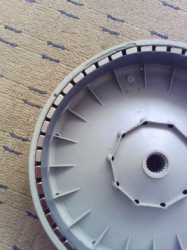

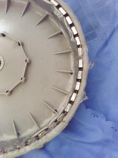
i then poured the resin 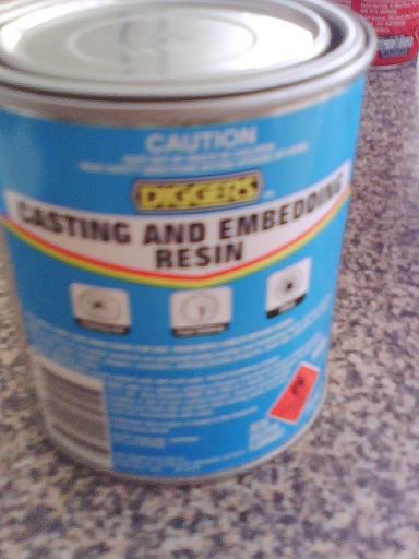
i also strenthened the rotor with a wrap of fiberglass cloth 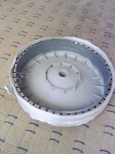

its a bit messy and will need to clean up when dry 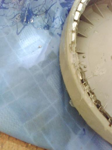
i will post a pic of the the completed unit when dry fingers crossed for the unvieling martin free power for all McAlinden WA |
||||
| Gizmo Admin Group Joined: 05/06/2004 Location: AustraliaPosts: 5182 |
Very good work Martin. Cant wait to see how it goes. Glenn The best time to plant a tree was twenty years ago, the second best time is right now. JAQ |
||||
| Gill Senior Member Joined: 11/11/2006 Location: AustraliaPosts: 669 |
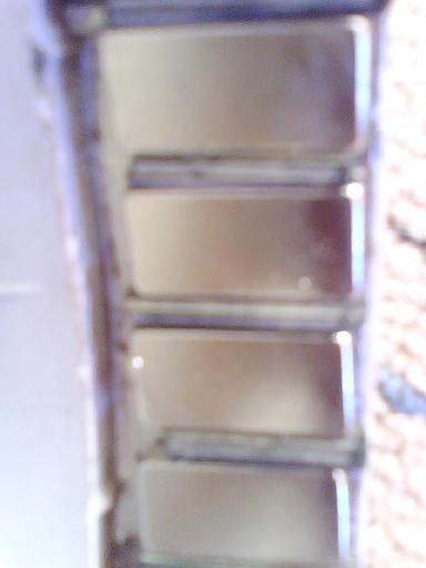
Martin, I used duct tape on an earlier project and found it blistered badly from heat and/or chemical reaction and leaked resin everywhere. What a mess. I swore never to use that again. I thought masking tape may be better as the paper would not blister like the plastic does. Did you have any difficulties in that area? If so, what do think would be better for next time? Your Magnet spacing looks regular and very neat. I measure the angle on the new F&P hub as 12deg to form the arrow head, so that equals 6deg across the full width. But they round the poles as well for even less cogging so it's difficult to know what will work best. What is the angle you set yours to? We're all hoping it goes well. 
was working fine... til the smoke got out. Cheers Gill _Cairns, FNQ |
||||
| martinjsto Senior Member Joined: 09/10/2007 Location: AustraliaPosts: 149 |
hi guys, you are right gill,i just removed the duct tape and the duct tape had blistered a bit leaving the finnish a bit irregular, i didnt get any leakage only where i spilt the resin whilst pouring, choice now is whether to clean up the mess or remove the magnets b4 it sets completely. i have a lathe so if the runnout isnt too much i might just skim it and sand down to smooth. i realy didnt set the angle i found as i mounted the magnets i could only twist so far and then the magnets rocked so i reduced the angle untill i found the best seating position without being upwright. i think i have about 6 to 8 degrees i will check with the protractor after cleanup. the job looks good with good resin penetration thro-ought i will also do more strengthening of the outside diameter probably increase it about 5 tp 8 mm. i read someware the metal laminations are to reduce the "flux" affect from rotation magnetic field. im not sure what that is but as i am using much more stronger magnets would extra metal bands help ballance the rotor in an electronic term not wieght/vibration? martin free power for all McAlinden WA |
||||
| FandPwithPVC Regular Member Joined: 09/09/2006 Location: Posts: 64 |
Hi Guys I made 3 Neo conversions some time back. The first one failed due to an out of round rotor. The second one developed problems with cracking from the resin mix . The third one worked okay but our mills at the time were not torquey enough . It also developed a out of round fault. Anyhow some HOW TO SUGGESTIONS 1 Find some MDF/CUSTOMWOOD and use it for spacers. Make them longer than the magnets and remove after the duct tape but before the resin. 2 Cut small angled pieces of wide duct tape and put them down in line withe magnets You will need about 12 of them 3 Once you have mixed you resin put it in a sauce bottle then blow it in and you will not get any mess. Regards Dennis L |
||||
| martinjsto Senior Member Joined: 09/10/2007 Location: AustraliaPosts: 149 |
cheers dennis, seems to be a fact of life that things dont always work the way we think they might. but i guess thats the way it is, help from these such sugestions on this site goes along way to avoid similar problems. im going to realy re-enforce the rotor on the outside I also thought of turning a bowl out of hardwood to tightly fit over the outside circumference then bonding together. also i was thinking of filling all the inside free area with resin. the idear is to create a flywheel effect from the excessive weight gained (also added strenght). i will also set up in lathe polish smooth, and ensure it is accentric to the magnets and spline hopefully the finished unit might weigh a bit but would be strong and wont flex and as i have large blades on my existing mill, should get going and want to keep going. good idear about the bottle , after my first pour i was thinking of using a similar aproach next time. martin free power for all McAlinden WA |
||||
| GWatPE Senior Member Joined: 01/09/2006 Location: AustraliaPosts: 2127 |
Hi Martin, A simple way to see if extra iron is needed, is to check for a residual magnetic field on the outside of the rotor. If the field from the neo magnet is contained by the iron band in the rotor, then a thin piece of iron will not be attracted to the outside of the rotor. This can be done on a rotor OFF the splined shaft. Any iron ring etc, may be of little electrical benefit placed on the outside of the fibreglass cloth you have laminated to the rotor. Did other members who have done a conversion notice any external magnetic field? It is possible that the small size and thickness of the neo magnets used in the conversion results in minimal field exiting the original iron band in the rotor anyway. I noticed with my mill, [axial flux], that the 44 x 5mm high tensile cap screws [one behind each 1" square x 0.5" thick Neo magnet], that hold the iron rings and magnets to the 0.5" thick aluminium plate rotor housing, had a slight magnetic attraction when the generator was disassembled. Upon assembly the magnetic fields strengthened and became fully contained within the rotor and no residual external field appeared on the above screws. no external field is a good thing. cheers, Gordon. become more energy aware |
||||
| Tinker Guru Joined: 07/11/2007 Location: AustraliaPosts: 1904 |
Hi Martin, The hardwood bowl is a novel idea but I think the wood grain is not oriented favourably all around to resist centrifugal forces. It might also crack from weather influences. If I were faced with this reinforcing task I would use what the armature winders were using to restrain the wiring on large rotors. They wound a tight spiral of piano wire around, with the ends locked in place by bent over metal strip ends. The strips were placed before the wire was wound over it. The wire could then additionally be covered with glass tape and resin if you so wish. Whatever you use, keep in mind that keeping the thing balanced is importand to minimise eccentric loading. Tinker Klaus |
||||
| brucedownunder2 Guru Joined: 14/09/2005 Location: AustraliaPosts: 1548 |
Hi crew,, In a previous post I posted a step by step procedure for fixing the Neo magnets.. The ordinary plastic tape is useless,,use the fabric backed gaffa tape ,it withstands the heat of the resin and does not distort. Bruce Bushboy |
||||
| martinjsto Senior Member Joined: 09/10/2007 Location: AustraliaPosts: 149 |
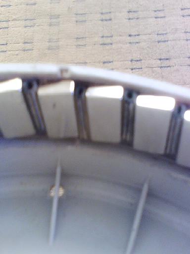
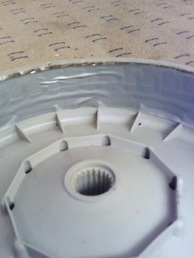
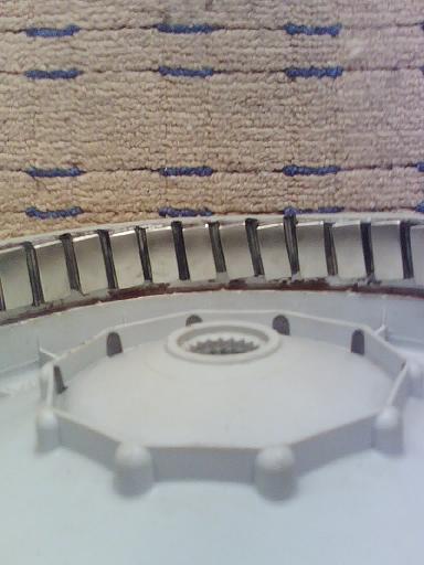
thanks for all the help guys, i have started the priliminary machining to clean up the rotor. i will be applying more resin and matting to the outside after cleanup and build up between machining. 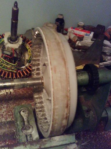
setup in lathe and check for runnout, looks within 0.5mm at this stage 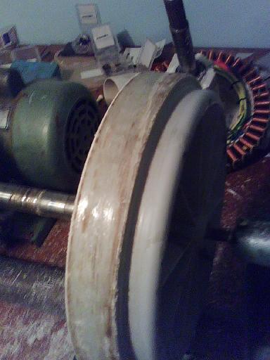
need to apply more resin inside as i didnt get even fill 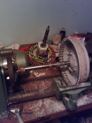
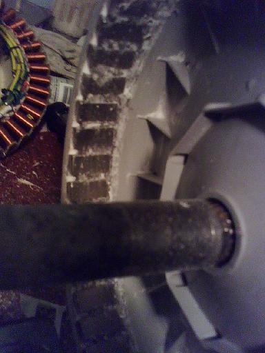
hard to see but very little runnout or vibration at this stage 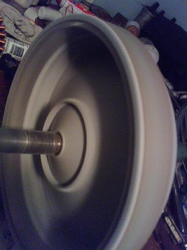
martin free power for all McAlinden WA |
||||
| imsmooth Senior Member Joined: 07/02/2008 Location: United StatesPosts: 214 |
I putting in an order today with a Chinese company to make slanted neo grade N45 magnets. They will be rhomboids with an 11deg angle, approximately 30mm x 11mm x 5mm. I plan to use glass resin to fix them and floor tile spacers to evenly separate them on the rotor. |
||||
| martinjsto Senior Member Joined: 09/10/2007 Location: AustraliaPosts: 149 |
sound like nice magnets imsnooth how much are they charging for them 5mm might be a good size as my 6mm are same as original ceramic but the extra strenght might cause some contact, have to wait and see martin free power for all McAlinden WA |
||||
| martinjsto Senior Member Joined: 09/10/2007 Location: AustraliaPosts: 149 |
i have found that there is a definate warpage when i assemble the stator and rotor. once about 1/3 on the unit grabs and binds up i tryed to decogg the stator to reduce adhersion but it didnt help. i reserched the brake drums, the ones used on the 5 bolt or 6 bolt landcrusiers are 11 inch inside diameter this is 279.4 mm the rotor has an external diameter of 277mm so im going to try resining the rotor to the drum. i will also drill pins through the complete assembly for added strenght, will post pics once i recieve the drum in about 1 week. martin free power for all McAlinden WA |
||||
| imsmooth Senior Member Joined: 07/02/2008 Location: United StatesPosts: 214 |
Martin, What grade were you using? N35, N42, N45? How much warpage was there? If the magnets were 5mm thick would it be ok do you think? What if they were 4mm thick? What I don't understand is if they magnets are symmetric, why does it warp? The forces should all be pulling equally towards the center. Jonathan |
||||
| martinjsto Senior Member Joined: 09/10/2007 Location: AustraliaPosts: 149 |
not sure jonathan, i purchased from the ausie magnet site www.aussiemagnets.com.au they were sold as rare earth neo magnets im not sure why i have warpage but as i slip the rotor on the stator, at about 1/3 way down you can deffinatly see two oposite sides touching whilst the other two sides have double clearance. during the first 1/3 the gap is equal, i think its a combination of flex on the plastic spline and deflection of the rotor. the brake drum should solve the issue and make it very ridgid the spline could still be an issue but. i have checked in the lathe and the magnets are within .25mm now after i ground them with an internal sufrace grinder (home made) martin free power for all McAlinden WA |
||||
| clarence Regular Member Joined: 27/10/2006 Location: Posts: 63 |
gidday Martin. I got 50 of those magnets too when they were on special. I found the perfect drum for my 7 phase conversion. A mazda light truck 6 stud brake drum. the ones I found were worn to the extent that the stator and magnets fitted perfectly with about 1/2 mm gap, but less worn ones could be machined easily. the outer wall thickness is at least as thick as the magnets. I have been toying with the idea of keying 48 magnet sized slots in the drum approx 1/2 mm deep [flattening the arc] to aid placement and structural integrity. These magnets should give serious power I am hoping, but I am a little unsure of the effect the width will have. they may be a tad too wide. only testing will tell I spose. cheers clarence. |
||||
| The Back Shed's forum code is written, and hosted, in Australia. | © JAQ Software 2026 |
