Notice. New forum software under development. It's going to miss a few functions and look a bit ugly for a while, but I'm working on it full time now as the old forum was too unstable. Couple days, all good. If you notice any issues, please contact me.
Bryan1 Guru Joined: 22/02/2006 Location: AustraliaPosts: 2101
Posted: 05:23am 08 Mar 2026
Copy link to clipboard
Print this post
Verified the TIP chips are the right ones and I did get them from Digikey too.
Q14 Gate to source 1.9K Gate to drain 300K
Q19 Gate to source 1.9K Gate to drain 1.7M
Q25 Gate to source 1.9K Gate to drain 250K
tinyt Guru Joined: 12/11/2017 Location: United StatesPosts: 559
Posted: 05:47am 08 Mar 2026
Copy link to clipboard
Print this post
Gate to Source circuit resistor = 20K each. there are 6 mosfets in parallel so total resistance - 20/6 = 3.33K. In parallel with 5k: 2k approx, your reading = 1.9k.
Problem is I don't know expected resistance between gate to drain. Are Q19 - Q24 open? I don't know.
If you have a spare mosfet, try this experiment. 1. Measure resistance between source(DMM negative probe) and drain(DMM positive probe). It should show very high resistance. 2. With the DMM negative probe still at source, touch the gate with the DMM positive probe. 3. then do step 1, it should read low resistance for a while then go to high resistance.
But you cannot do this because the mosfets are in-circuit unless you un-solder some more board components. Are you willing to do this?
Edit: I forgot, can you measure resistance: Source to Drain of the mosfets you measured with the probes one way and then reversed?
Edit2: Some of the TIP transistors you unsoldered are probably bad now. Edited 2026-03-08 15:58 by tinyt
Bryan1 Guru Joined: 22/02/2006 Location: AustraliaPosts: 2101
Posted: 05:59am 08 Mar 2026
Copy link to clipboard
Print this post
Sure am Tinyt if it is needed
So I went and took some resistance measurement of each leg with the mosfets
Q3 to Q8 gate to source 1.9K gate to drain 1.7M
Q9 to Q14 gate to source 1.9K gate to drain 300K
Q25 to Q30 gate to source 1.9K gate to drain 300K
Q19 to Q24 gate to source 1.9K gate to drain 1.7M
Now each legs 5 mosfets did all measure the same as each other.
Just measured a new mosfet and the source/drain pins are both in the mega ohm range
Bryan1 Guru Joined: 22/02/2006 Location: AustraliaPosts: 2101
Posted: 06:12am 08 Mar 2026
Copy link to clipboard
Print this post
Well I may aswell go for a drive down the hill and get some new TIP chips and replace all of them, then unsolder each mosfet so they can be tested out of circuit and replaced if any are suspect. Edited 2026-03-08 16:12 by Bryan1
tinyt Guru Joined: 12/11/2017 Location: United StatesPosts: 559
Posted: 06:51am 08 Mar 2026
Copy link to clipboard
Print this post
My recommended steps:
1. Unsolder all mosfets.
2. Replace all TIPs.
3. Power on the board.
4. Scope the corner diodes or mosfet gate pads and confirm you have the same waveforms as the outputs of the picoverter board.
5. If waveforms are confirmed good, then solder only 1 mosfet to each heatsink.
6. Re-test and measure AC output of the toroid.
7. If AC output is good, add more mosfets to each heatsink and re-test.
Bryan1 Guru Joined: 22/02/2006 Location: AustraliaPosts: 2101
Posted: 10:25pm 08 Mar 2026
Copy link to clipboard
Print this post
Ok TIP41C and the TIP42C were ordered last night from Jaycar, now first I tried Altronics as they were cheaper but they wouldn't accept the part number for the TIP42C so looks like they had no stock. Thats twice now trying to do an order from them only find they have no stock of a part.
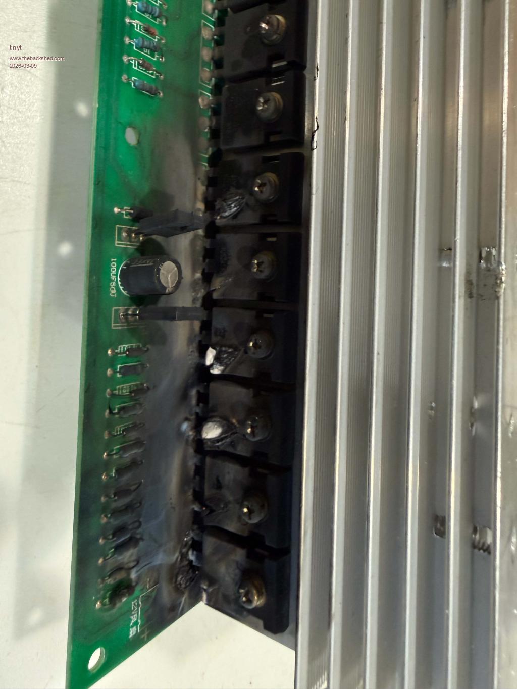
So today time to remove those mosfets and see how many survived.
Bryan1 Guru Joined: 22/02/2006 Location: AustraliaPosts: 2101
Posted: 11:11pm 08 Mar 2026
Copy link to clipboard
Print this post
Ok got Q3 from VS2 high side off and doing a ohms check against the new mosfet Q3 is still good
Q14 from VS1 low side also proved good.
So my plan is remove one from each leg and check as one would think lets say if VS1 low side had a blown mosfet the whole leg would be gone. Edited 2026-03-09 09:23 by Bryan1
phil99 Guru Joined: 11/02/2018 Location: AustraliaPosts: 3293
Posted: 11:20pm 08 Mar 2026
Copy link to clipboard
Print this post
Tinyt's test at step 4 above is intended to be done with all MOSFETs removed, presumably to ensure the correct drive signals are present and the voltage does not sag, before adding any MOSFETs. Then steps 5 to 7 can be done. . Edited 2026-03-09 09:22 by phil99
Bryan1 Guru Joined: 22/02/2006 Location: AustraliaPosts: 2101
Posted: 11:43pm 08 Mar 2026
Copy link to clipboard
Print this post
Just unsoldered the other 2 legs and all mosfets have proved good so that is a good sign and only 16 to go.......
tinyt Guru Joined: 12/11/2017 Location: United StatesPosts: 559
Posted: 11:55pm 08 Mar 2026
Copy link to clipboard
Print this post
It might be worth it to try the experimental stand alone testing of the mosfet.
What it does is verify if the mosfet will conduct between source and drain when its gate recieves a positive charge with respect to source by touching its gate with the positive probe of the DMM in resistance mode. Just make sure the gate is not touching anything else.
Not sure if it can be done with any DMM, but I can do it with my fluke 179.
phil99 Guru Joined: 11/02/2018 Location: AustraliaPosts: 3293
Posted: 12:44am 09 Mar 2026
Copy link to clipboard
Print this post
My Fluke 177 doesn't provide enough voltage on the resistance range but does on the diode test range. Holding the black probe on the source put the red probe on the drain, the meter reads "OL". Briefly touch the red probe on the gate then move it back to the drain, now it reads about 1V (depends on the MOSFET) and holds there for a long time.
A 9V battery and clip lead does a better job. Meter on resistance and probes on source and drain, touch 9V on the gate and resistance drops almost to 0Ω and stays for a long time.
tinyt Guru Joined: 12/11/2017 Location: United StatesPosts: 559
Posted: 01:20am 09 Mar 2026
Copy link to clipboard
Print this post
You are right with the 9V battery.
For reference using my fluke 179 meter on a new HY5608. In ohms range: Initially discharging gate by shorting it to source, then Negative on drain positive on source - 250k. Negative on source positive on drain - OL Mohms. Negative on source, touch the gate with positive, then positive on drain - 0 ohm
In beeper range: Initially discharging gate by shorting it to source, then Negative on drain positive on source - 430 ohms. Negative on source positive on drain - OL ohms. Negative on source, touch the gate with positive, then positive on drain - 0 ohm
In diode test range: Initially discharging gate by shorting it to source, then Negative on drain positive on source - .430 vdc. Negative on source positive on drain - OL vdc. Negative on source, touch the gate with positive, then positive on drain - .001 vdc.
Bryan1 Guru Joined: 22/02/2006 Location: AustraliaPosts: 2101
Posted: 02:33am 09 Mar 2026
Copy link to clipboard
Print this post
Ok got all the mosfets off and with the black lead always in my left hand gate to source was totally isolated the same as gate to drain, now drain to source was 2.4M on all the mosfets.
Just doing the final things to get the tests started so a bit of advise for the scope tests will be nice.
Bryan1 Guru Joined: 22/02/2006 Location: AustraliaPosts: 2101
Posted: 02:59am 09 Mar 2026
Copy link to clipboard
Print this post
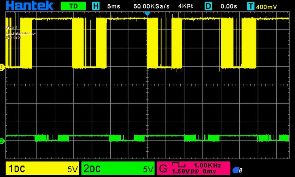
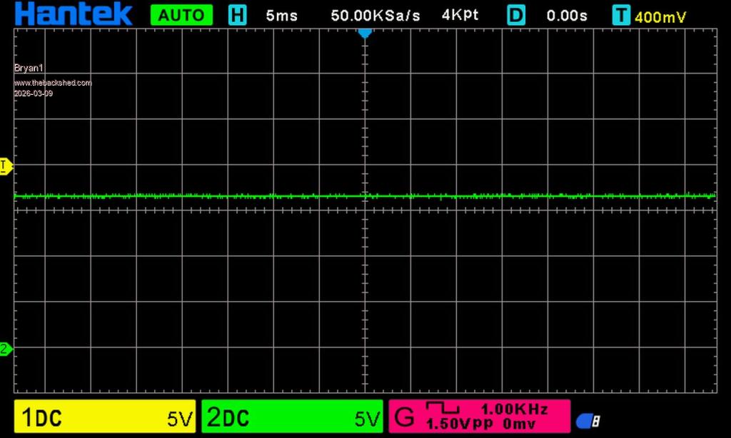
first scope test
Ch1 to D1 Ch2 to D7 Gnd
Bryan1 Guru Joined: 22/02/2006 Location: AustraliaPosts: 2101
Posted: 03:26am 09 Mar 2026
Copy link to clipboard
Print this post
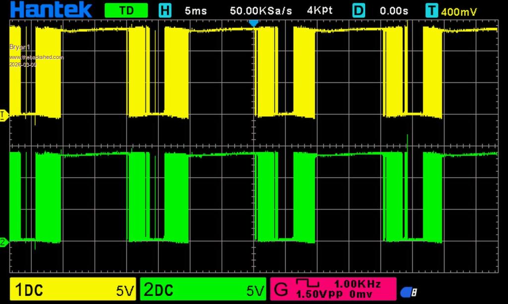
VS1 Low side
CH 1 pin 1 on the TIP42 CH 2 pin 1 in the TIP41
VS 2 low side same setup
more to come
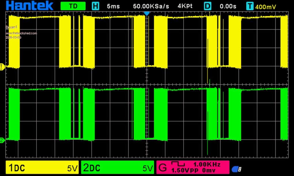
VS1 high side
VS 2 high side
So it does look like the high side TIP's are gone. Edited 2026-03-09 13:35 by Bryan1
Bryan1 Guru Joined: 22/02/2006 Location: AustraliaPosts: 2101
Posted: 06:04am 09 Mar 2026
Copy link to clipboard
Print this post
Just checked the tracking of the package from Jaycar and it should be here in the morning
mab1 Senior Member Joined: 10/02/2015 Location: United KingdomPosts: 282
Posted: 10:03am 09 Mar 2026
Copy link to clipboard
Print this post
Just a sanity check on the high side scope tests:-
Did you remember to pull the 'low side' of the high side totem poles (i.e. VS1 and VS2) to gnd for the high side tests? If vs1 and vs2 are left floating, the bootstrap caps won't charge i think.
I'm not sure which diodes D1 and D7 are, so i don't know if those scope tests look right or not.
tinyt Guru Joined: 12/11/2017 Location: United StatesPosts: 559
Posted: 01:26pm 09 Mar 2026
Copy link to clipboard
Print this post
Agreed. Also, Bryan's scope traces are confusing. TIP41 pin 1 and TIP42 pin 1 of the pair are connected together on the board, so Bryan's green trace is a duplicate of the yellow trace.
D1, D7 traces seem to show something wrong by the low P-P voltage of the green trace (D7) but I am no sure yet.
Bryan, let us see if this will work with all mosfets still unsoldered. 1. Disconnect ribbon cable. Temporarily connect the power board VS1 and VS2 to GND. 2. Apply 24vdc from the psu thru the resistor bank and post current draw. 3. Post voltage readings from the 3 pins of the TIP35. If they are higher than 9 volts, proceed to next step. 4. Connect ribbon cable and turn on the picoverter. Post 24vdc psu current draw. And TIP35 pins voltages. 5. Connect scope CH1 and CH2 probe grounds to power board GND. 6. Connect scope CH1 probe to R1(does not matter which lead) and scope CH2 probe to D1 (does not matter which lead). Post scope screen. This should be L01 drive signal. 7. Connect scope CH1 probe to R26(does not matter which lead) and scope CH2 probe to D7 (does not matter which lead). Post scope screen. This should be L02 drive signal. 8. Connect scope CH1 probe to R27(does not matter which lead) and scope CH2 probe to D18 (does not matter which lead). Post scope screen. This should be H01 drive signal. 9. Connect scope CH1 probe to R52(does not matter which lead) and scope CH2 probe to D19 (does not matter which lead). Post scope screen. This should be H02 drive signal. 10. Remove VS1, VS2 short to GND after the test.
Bryan, sorry if this is too much to do, but I am trying to avoid this to happen to your power board.
Edited 2026-03-10 00:55 by tinyt
Bryan1 Guru Joined: 22/02/2006 Location: AustraliaPosts: 2101
Posted: 09:13pm 09 Mar 2026
Copy link to clipboard
Print this post
Thanks for those scope tests tips Tinyt
Now when I was testing yesterday and found the high side TIPS weren't showing anything I did measure some voltages. Those fast diodes were showing 17 volts and the TIP31 was 17.7 VBat 17 volts with the 18V zener on 17.7 volts
It was a bit of fun unsoldering all those mosfets and on 2 legs I did lose the track from the track to the 4R7 resistor. Well with 6 mosfets for each leg and just leave that those 2 blank mosfet pads.
As I am using HY5608 mosfets 4 of them should be plenty
phil99 Guru Joined: 11/02/2018 Location: AustraliaPosts: 3293
Posted: 09:44pm 09 Mar 2026
Copy link to clipboard
Print this post
The track to the 4R7 resistor can easily be replaced with thin wire curled around and soldered to the leg at each end of the missing track.
Page 20 of 28
Print this page
The Back Shed's forum code is written, and hosted, in Australia.