Notice. New forum software under development. It's going to miss a few functions and look a bit ugly for a while, but I'm working on it full time now as the old forum was too unstable. Couple days, all good. If you notice any issues, please contact me.
Bryan1 Guru Joined: 22/02/2006 Location: AustraliaPosts: 2100
Posted: 02:45am 11 Mar 2026
Copy link to clipboard
Print this post
ok got my dremmel out and FINALLY got the track and pad isolated
So one happy camper anyway the tummy bones are screaming so after lunch let the fun start.
tinyt Guru Joined: 12/11/2017 Location: United StatesPosts: 559
Posted: 03:28am 11 Mar 2026
Copy link to clipboard
Print this post
I am not a QC guy but it seems that on most components, solder did not wick the component pins to the top side of the PCB.
I would touch them up with solder again to avoid future problems. Maybe let the tip of the soldering iron heat the joint a little bit longer but just enough so solder will flow better.
Also, to be safe, do the 10 steps in my earlier post. Edited 2026-03-11 13:32 by tinyt
Bryan1 Guru Joined: 22/02/2006 Location: AustraliaPosts: 2100
Posted: 04:33am 11 Mar 2026
Copy link to clipboard
Print this post
Ok took your advise Tinyt and soldered in from the top side to ensure every component connected, now I have soldered the caps back in and tied VS1 and VS2 to Gnd turned the unit on and after the caps had charged the idle current was 59mA
So I do think it's safe to say I can now solder in the new TIP41 and TIP42 chips back in so I can do all those tests again.
Godoh Guru Joined: 26/09/2020 Location: AustraliaPosts: 667
Posted: 04:54am 11 Mar 2026
Copy link to clipboard
Print this post
HI Bryan, great to hear that you have found a short. I hope that the board runs well after putting it all back together. Was the short a fault in manufacturing , or a solder bridge? Anyway good luck, it has been a long project, I am sure you will be a happy fellow when it fires up. Pete
Bryan1 Guru Joined: 22/02/2006 Location: AustraliaPosts: 2100
Posted: 05:23am 11 Mar 2026
Copy link to clipboard
Print this post
Ok here is the first scope pic
VS1 and VS2 tied to ground
Ch1 to D1 VS1 low Ch2 to D7 VS2 low
Next scope test Edited 2026-03-11 15:51 by Bryan1
Bryan1 Guru Joined: 22/02/2006 Location: AustraliaPosts: 2100
Posted: 05:54am 11 Mar 2026
Copy link to clipboard
Print this post
Test 6. CH1 to R1 Ch2 to D1
Test 7. CH1 to R26 CH2 to D7
Test 8. CH1 to R27 CH2 to D18
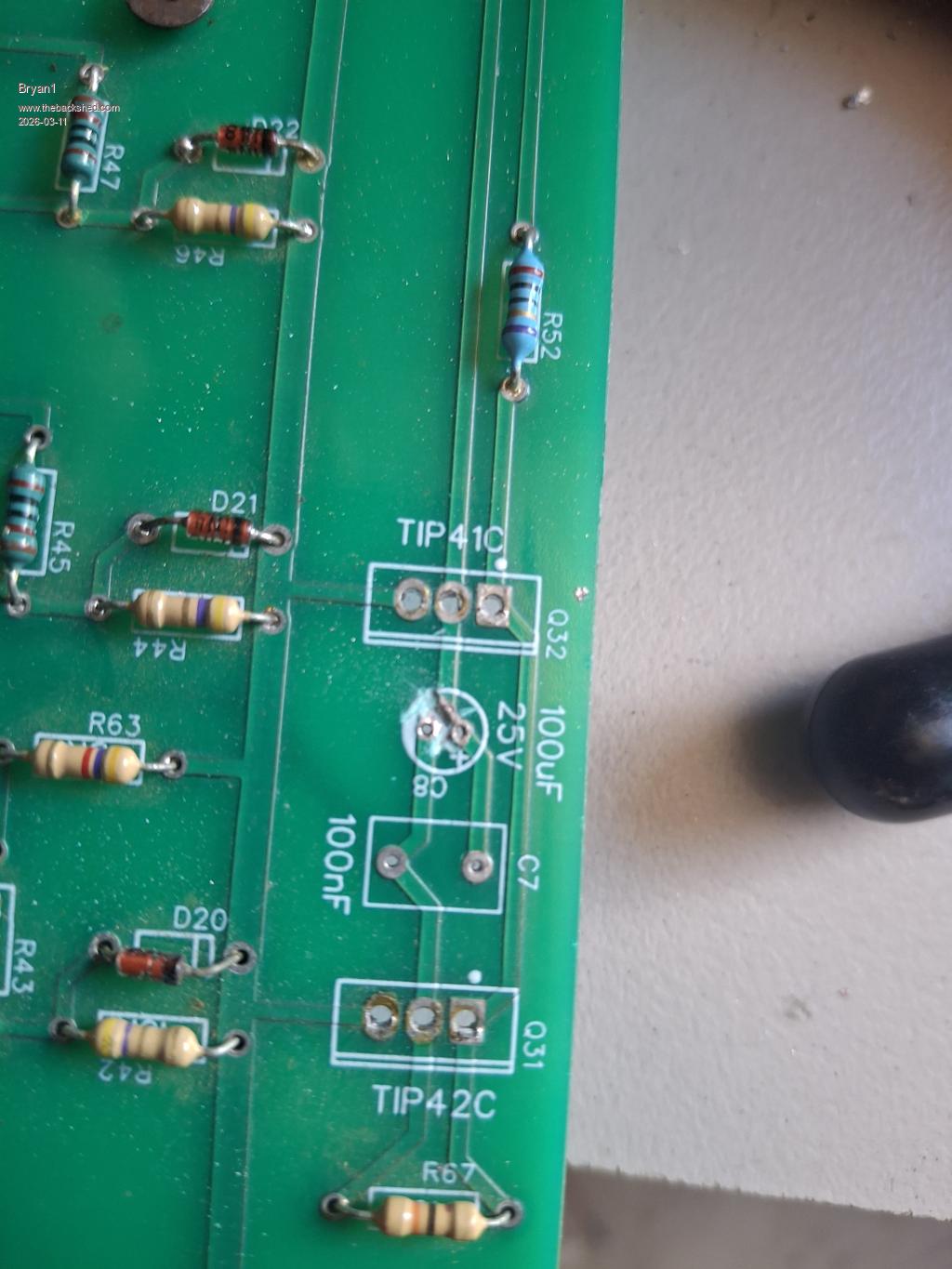
Test 9. CH1 to R52 CH2 to D19
So still got a problem there somewhere
Bryan1 Guru Joined: 22/02/2006 Location: AustraliaPosts: 2100
Posted: 06:18am 11 Mar 2026
Copy link to clipboard
Print this post
Ok this is plain weird
D26 anode voltage measurement
D26 Cathode voltage measurement
They do say a picture says a 1,000 words like If I said D26 anode was 30 volts from a 24 volt supply some question may of been raised.
phil99 Guru Joined: 11/02/2018 Location: AustraliaPosts: 3293
Posted: 07:54am 11 Mar 2026
Copy link to clipboard
Print this post
I don't have the circuit diagram so just guessing. The high-side MOSFET gates need to be higher than the V+ rail so perhaps D26 is part of a high-side bootstrap circuit that provides the boosted voltage.
tinyt Guru Joined: 12/11/2017 Location: United StatesPosts: 559
Posted: 12:52pm 11 Mar 2026
Copy link to clipboard
Print this post
Both signals look good.
tinyt Guru Joined: 12/11/2017 Location: United StatesPosts: 559
Posted: 01:00pm 11 Mar 2026
Copy link to clipboard
Print this post
Test 6. What happened here? Peak to peak for D1 shows about 1.3 volts while previous post shows peak to peak of 13 volts.
Test 7. What happened here? Peak to peak for D7 shows about 1.3 volts while previous post shows peak to peak of 13 volts.
Any setup changed from the previous post? Edited 2026-03-11 23:01 by tinyt
tinyt Guru Joined: 12/11/2017 Location: United StatesPosts: 559
Posted: 01:08pm 11 Mar 2026
Copy link to clipboard
Print this post
H01 signal from picoverter missing, hopefully just loose connection in the ribbon cable or mating sockets. With power off, ohm out H01 signal from picoverter to power board R27
Footnote added 2026-03-11 23:14 by tinyt Do not disconnect ribbon cable, leave it as is until you have ohm'ed out the H01 signal. If you disconnect prior, the problem might disappear.
tinyt Guru Joined: 12/11/2017 Location: United StatesPosts: 559
Posted: 01:11pm 11 Mar 2026
Copy link to clipboard
Print this post
This looks good.
Bryan1 Guru Joined: 22/02/2006 Location: AustraliaPosts: 2100
Posted: 11:59pm 11 Mar 2026
Copy link to clipboard
Print this post
Morning Guy's well with those scope pic's yesterday got egg on my face as the earth lead for the scope wasn't connected.
So this morning used the scope and found L01, L02 and H02 all showed the correct waveforms but H01 is still offline.
Now trying to ohm the pin for H02 on the 10 pin connector on the power board to the 20 ohm resistor(R27) is in the kilo ohm range. Now as this pin does have it's track on the top layer I'm sure my soldering isn't going all the way up.
Also checking the IR2184 to R27 was open circuit so changed the chip and found it was in the kilo ohm range not open circuit, now with with L01, L02 and H02 the ohm check was in the low ohm range.
OK I may of found a fix soldered in a jumper wire from the H01 pin on the 10 pin connector to the base of R27 so it now a solid connection.
Time to test this hack out Edited 2026-03-12 10:18 by Bryan1
Bryan1 Guru Joined: 22/02/2006 Location: AustraliaPosts: 2100
Posted: 12:42am 12 Mar 2026
Copy link to clipboard
Print this post
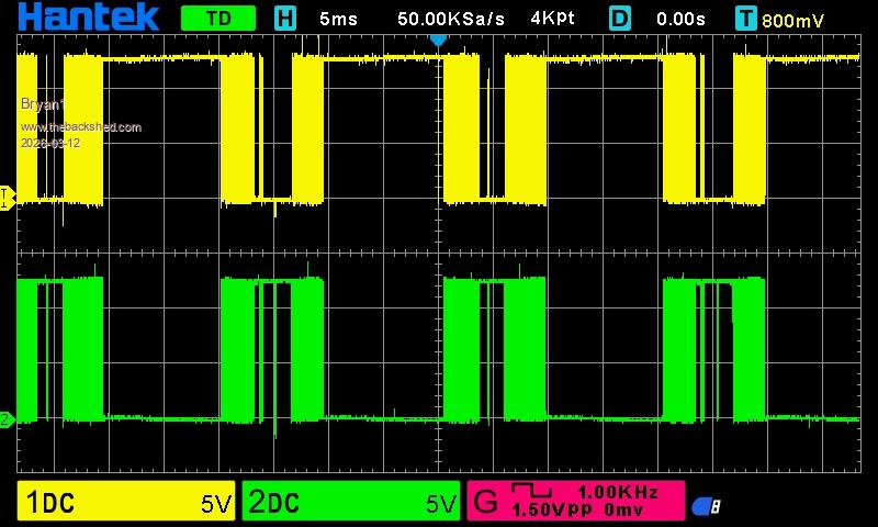
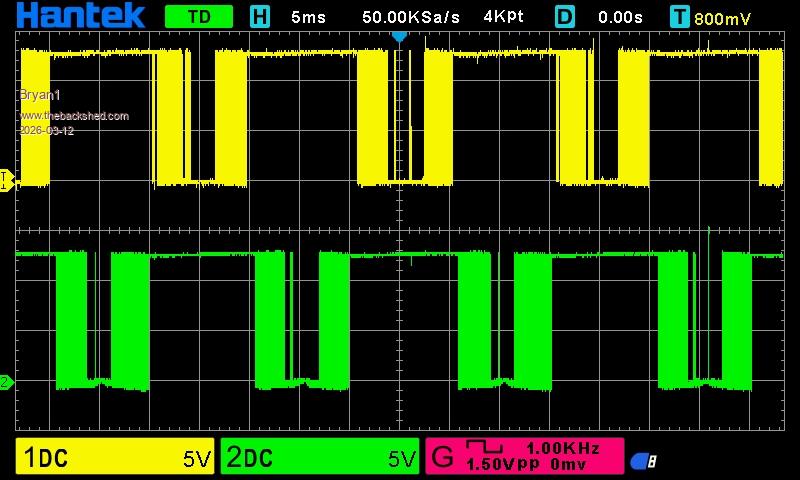
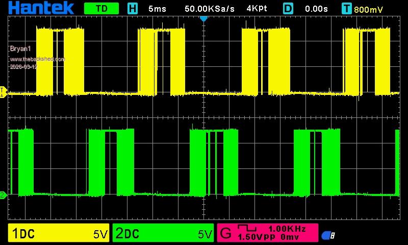
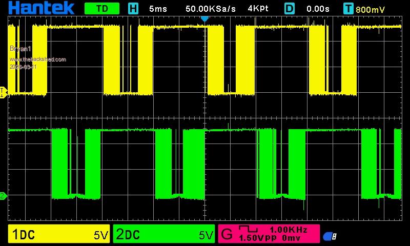
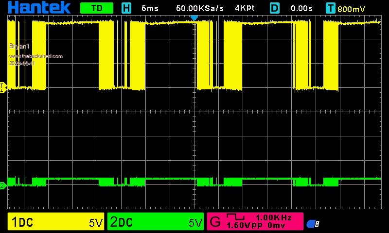
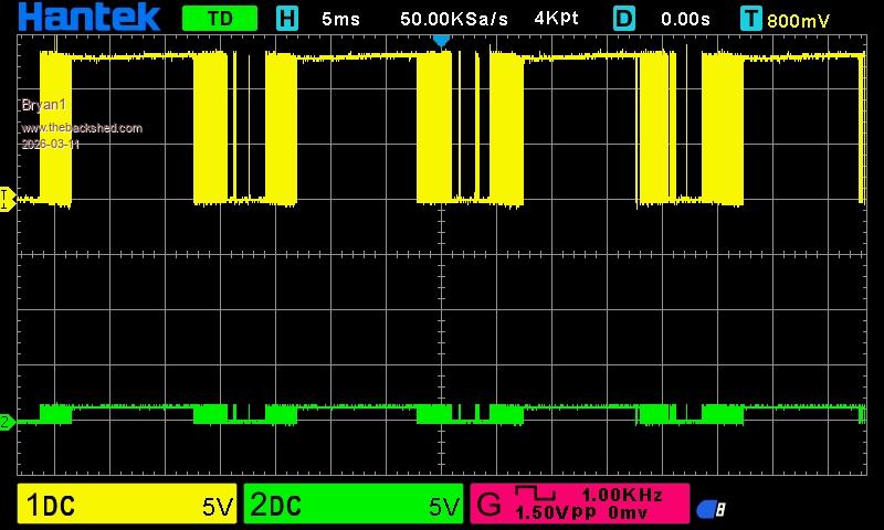
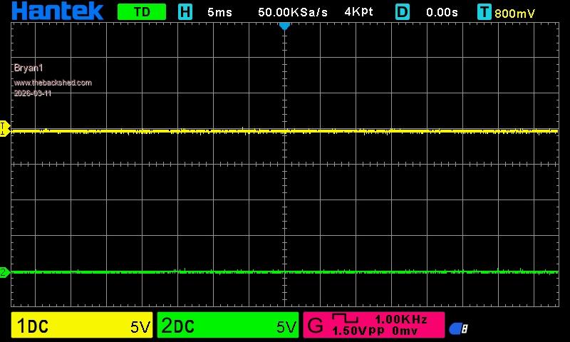
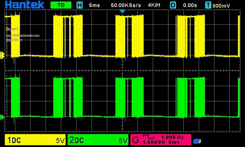
Ok scope pic's
Ch1 L01 CH2 L02
Ch1 L01 Ch2 H01
Ch1 L02 Ch2 H02
Ch1 H01 Ch2 H02
So I do think it's time to add a mosfet to each leg and see if this energy meter works
Godoh Guru Joined: 26/09/2020 Location: AustraliaPosts: 667
Posted: 12:58am 12 Mar 2026
Copy link to clipboard
Print this post
Good luck with it Bryan. I hope it works this time. Pete
tinyt Guru Joined: 12/11/2017 Location: United StatesPosts: 559
Posted: 01:39am 12 Mar 2026
Copy link to clipboard
Print this post
If the mosfets you are going to install are not new, I suggest you do the gate charge test prior to soldering.
Bryan1 Guru Joined: 22/02/2006 Location: AustraliaPosts: 2100
Posted: 02:03am 12 Mar 2026
Copy link to clipboard
Print this post
Well just soldered one mosfet on each leg and on setting up for the first test so I will soon see if the fets are bad
Bryan1 Guru Joined: 22/02/2006 Location: AustraliaPosts: 2100
Posted: 02:35am 12 Mar 2026
Copy link to clipboard
Print this post
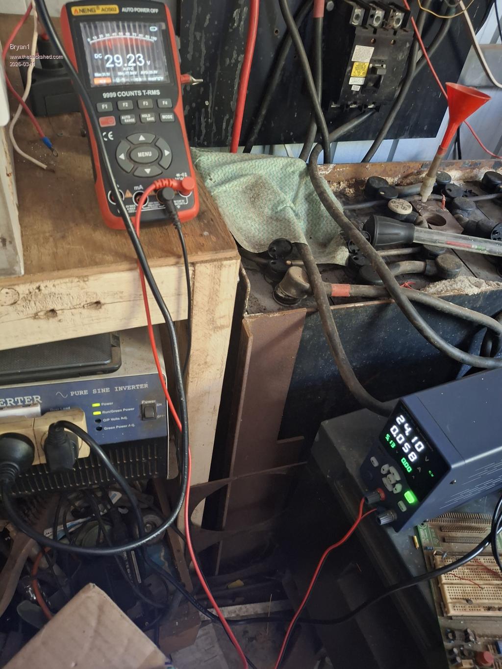
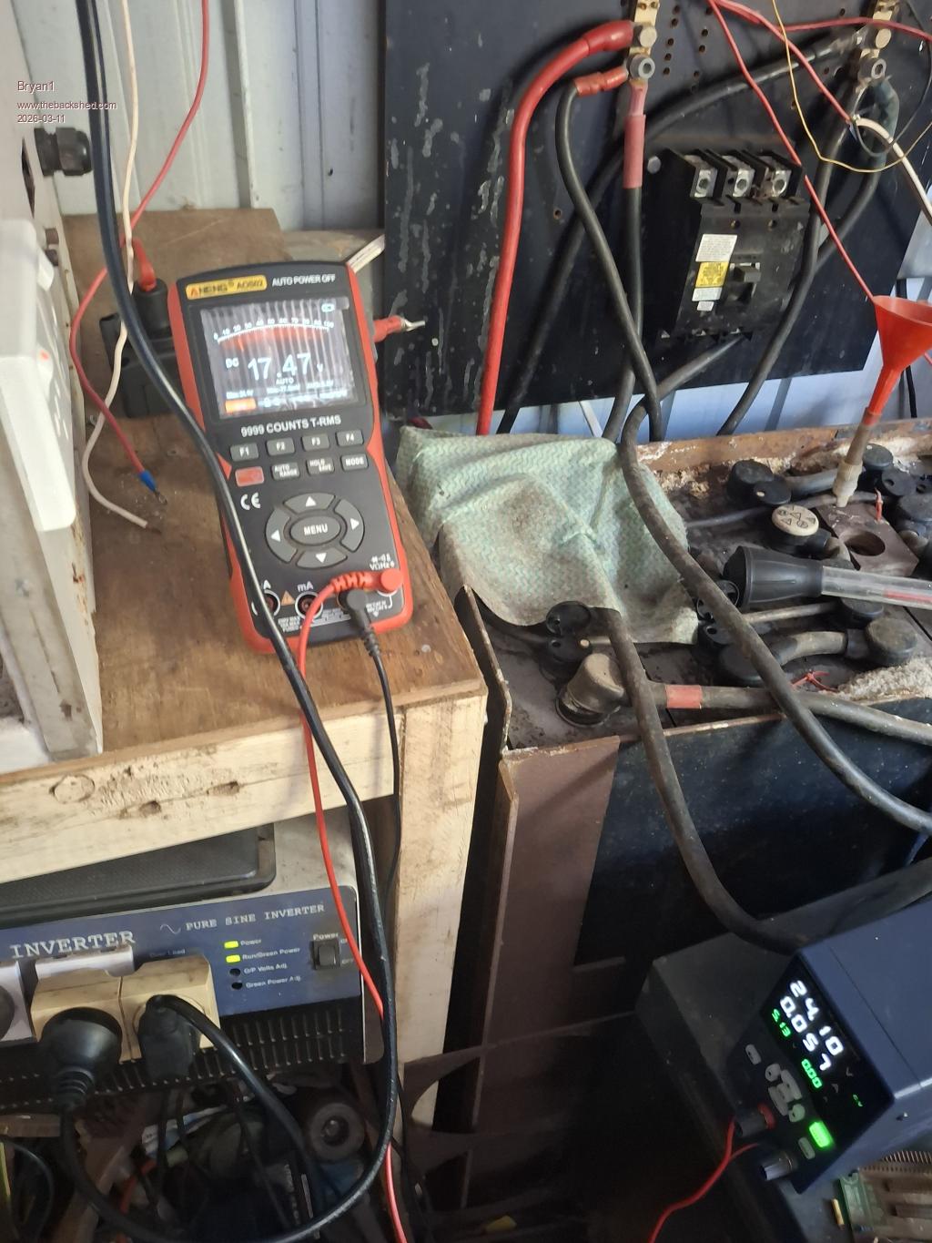
Well got the first glimpse of the energy meter for a few seconds so took the toroid output off the AC board and connected my DMM where I got to see 25 volts AC then this ticking was heard from the inverter box.
So looks like new mosfets are going in
tinyt Guru Joined: 12/11/2017 Location: United StatesPosts: 559
Posted: 02:50am 12 Mar 2026
Copy link to clipboard
Print this post
I suggest you scope all signals again to make sure none of the TIPs are damaged.
Bryan1 Guru Joined: 22/02/2006 Location: AustraliaPosts: 2100
Posted: 03:34am 12 Mar 2026
Copy link to clipboard
Print this post
That was good idea mate as the H02 TIP's are showing zero voltage on all pins, now the other 3 legs are showing the correct waveforms.
Page 22 of 28
Print this page
The Back Shed's forum code is written, and hosted, in Australia.


 as the earth lead for the scope wasn't connected.