
|
|
Forum Index : Electronics : Inverter building using Wiseguys Power board and the Nano drive board
| Author | Message | ||||
| KeepIS Guru Joined: 13/10/2014 Location: AustraliaPosts: 2206 |
In case anyone is interested. I finally had some MS226060-2 arrive from an AliExpress site that has the slowest delivery time I've seen, Site keeps saying my order is canceled due to shipping delays, then they issues a new consignment tracking number, no tracking info and then after a month or so, it suddenly appears at my doorstep via DHL. Toroids 57.1x26.4x15.2mm It's the last on on the list, click "View More" to expand the list (57.1x26.4x15.2mm) These are the original meatier (smaller hole) Blue Toroids that I use, they will just fit 5 turns through a six Stack of Toroids for around 23uH, 4 turns will give 16uH. You need 12 of these Toroid Rings to make two x 6 stack chokes at either 16uH or 23uH, the price shown is for a 3 pack. And just to make me want to bash my head against the sharp edge of a desk  Replacing a temporary 40uH Toroid choke in one side of the "Test Inverter" with one of these 23uH chokes, which matches the existing 23uH choke in the other side, has completely eliminated the Buzz I could induce into the Toroid by fast stepping the DC input up or down. It still makes a slight Buzz as you fast step the Voltage up, but as soon AC regulation is reached, the buzz stops and the Toroid remains silent (ear against the Toroid) Made a slight miscalculation in the Inductance, 4 turns 16uH, 5 turns 23uH. 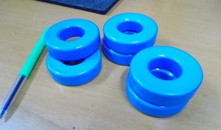 . Edited 2025-05-22 11:43 by KeepIS NANO:Inverter V 8.3ks - Linux AvrDude GUI script V4.1 |
||||
| KeepIS Guru Joined: 13/10/2014 Location: AustraliaPosts: 2206 |
There is a difference in the Toroids, these New units are marked as FM571060A, the old Toroids are MS226060-2. I cannot find any reference to FM571060A. They both give exactly the same Inductance for the Number of turns and are the same size. The newer units look to have a much softer curve. I have repeated the tests many times and every run is identical. Yellow: Current 125A per volt. Blue: Cap discharge voltage from 75V. Original MS226060-2 Toroids: 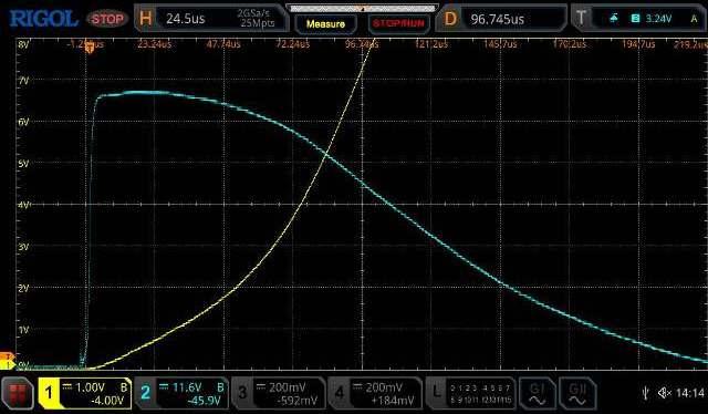 The New Toroids: 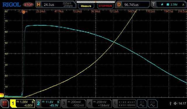 If you compress the time scale, the second image is virtually the same as the first, it's almost as though there is a small resistance in play? I rechecked the cable, both use the same cable, everything looks identical and the display for each as shown above is always exactly the same no matter how many times I swap them into the JIG. EDIT: At 625A, the Cap voltage (blue) has dropped from 75V to 58V, there is still plenty of reactance left. If the Choke is replaced with the same winding lenght cable, the Cap voltage trace is simply a narrow pulse from 50V to 0V ("almost" zero inductance). A single power board bank of FETS handling 625A would not see anything like a short, especially as there are effectively two chokes in series with the Toroid. So "32 FETS" and FOUR chokes in a Dual Inverter can easily handle 800A peak Induction motor start loads. BTW: I proved that if built correctly, a single wiseguy Power board with two chokes and one Toriod, can easily handle repetitive 650A Peak start loads daily for months. . Edited 2025-05-23 12:03 by KeepIS NANO:Inverter V 8.3ks - Linux AvrDude GUI script V4.1 |
||||
Revlac Guru Joined: 31/12/2016 Location: AustraliaPosts: 1288 |
Looks good, couldn't find any reference to that part number either...not that surprised that its not listed, quite a few of them don't seem to be listed, I have 2 large cores with unknown numbers.  Anyway it appears to have removed/dampened the Buzz sound, My old Mad inverter has a buzz sound when it starts the induction motor on the saw bench, start surge of about 8Kw, sounds a little like hitting it with a hammer as it still uses the old silicon steel U cores.  Cheers Aaron Off The Grid |
||||
| KeepIS Guru Joined: 13/10/2014 Location: AustraliaPosts: 2206 |
That's good to know, I'm very happy with the new cores. BTW I've been reviewing lots of old data from the Single 3 stack Toroid Inverter compared to the dual 3 stack Inverter and the startup currents have dropped in the dual. The power levels haven't, it's just the Dual Inverter having less AC SAG under extreme loads and recovery is quite fast. It's obviously why I'm getting zero flicker of overhead lights. AC voltage SAG is now so small that annoying pulsing loads have no chance, even switching 2.8 kW AC pulsing loads on top of an almost unloaded Inverter load of 200W, does absolutely nothing to the lights. To get a LED batten to flick once, I need around 12kW of load suddenly dropped across the AC output, seriously Impressive.  NANO:Inverter V 8.3ks - Linux AvrDude GUI script V4.1 |
||||
| analog8484 Senior Member Joined: 11/11/2021 Location: United StatesPosts: 204 |
Interesting that a small difference in chokes can make that much of a difference. I wonder if the older inverter builds using only one choke had more buzzing. |
||||
| KeepIS Guru Joined: 13/10/2014 Location: AustraliaPosts: 2206 |
I think the balanced chokes and inductance change just shifted the level needed to induce the buzzing, I realized that it just takes a bit more to get it to buzz  Many differences in earlier builds including different SPWM modulation compared to the Nano, and they often used buzzing ferrite E-core chokes, so many variations that to tie it down is again like trying to head cats. Put a resistive load on the inverter and the idle buzz is gone - my Inverter never idles NANO:Inverter V 8.3ks - Linux AvrDude GUI script V4.1 |
||||
| oreo Senior Member Joined: 11/12/2020 Location: CanadaPosts: 133 |
Here is a cross reference I pulled from the Karson's website 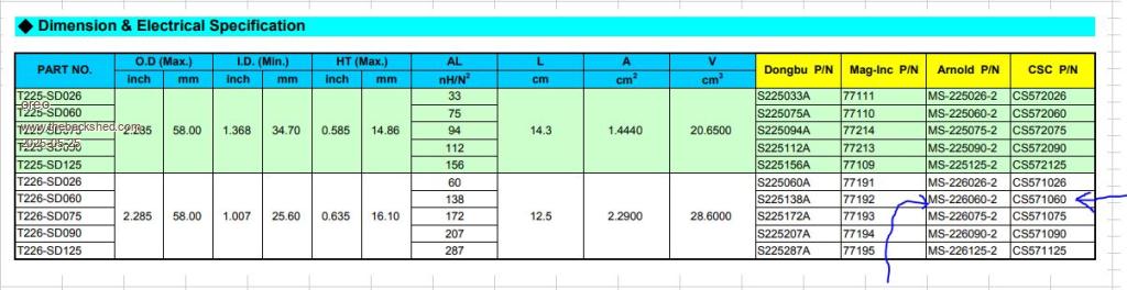 Different manufacturers unfortunately use different part numbering schemes, however the FM part number seems to follow the same scheme as CSC part number. However it is obviously not a standard sendust core material, because it saturates differently. Let's run a few calculations. Greg |
||||
| oreo Senior Member Joined: 11/12/2020 Location: CanadaPosts: 133 |
Using the curves from 6 MS226060-2 cores posted earlier by KeepIS. 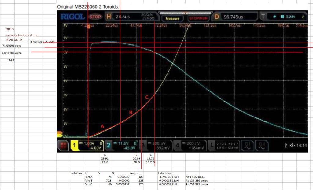 Now running the same setup in the Micrometals analyzer produces slightly different results. I do notice that KeepIS curves are a little funky in that the voltage is shown as going up for part of the curve, which is weird. Typically the Micrometal calculations match my curve calculations but regardless we can use this as a guide. 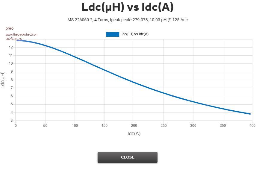 Now there are better core materials than Sendust. Here is a list of the Micrometals (Arnold cores) materials. 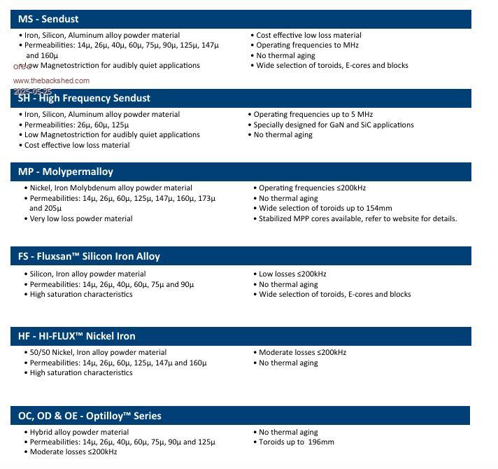 Now if I plug in a HF type core into the Analyzer tool, this is the graph I get. The FS type core produces slightly better results. These cores saturate slower than standard sendust. 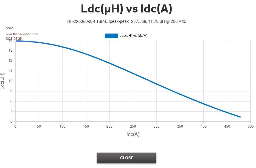 So it looks like KeepIS has discovered a core supplier that can supply cores with better characteristics than a standard sendust core. That is good to know! Greg |
||||
| oreo Senior Member Joined: 11/12/2020 Location: CanadaPosts: 133 |
On a different note, I was experimenting with the frequency setting on the inverter. Can you advise what difference we should be seeing from 60Hz to 60-Hz to 60-- Hz? thanks! Greg |
||||
| KeepIS Guru Joined: 13/10/2014 Location: AustraliaPosts: 2206 |
oroe thanks so much for that, I was going to ask you if you could run this through the Micrometal app as you did last time. This confirms my calculations and the much slower saturation curve for the Latest toroids  I'll look up the nominal difference at 60Hz when I get back, I'm not at the Workshop PC. The variation is small and the exact frequency will vary slightly between Nanos with Xtal accuracy, but you likely knew that. EDIT: these are ballpark figures, as I said will change slightly with xtal tolerances etc. It shifts roughly +- 0.08Hz. Let me know if yours is out? . Edited 2025-05-25 14:06 by KeepIS NANO:Inverter V 8.3ks - Linux AvrDude GUI script V4.1 |
||||
| KeepIS Guru Joined: 13/10/2014 Location: AustraliaPosts: 2206 |
I had already calculated the old Blue toroids and obviously got the same results, however these still don't show the real picture, especially as the Voltage sags and throws out the intersect points for accurate calculations, but good for comparing different sets of Chokes. I'm going to make a new Sat tester with max current limiting and stiffer Voltage, testing a choke at working voltage and current does change the results somewhat. BTW the Micrometals Sim above is 4 turns, I have 5 turns in these @ 22.6µH @ 20kHz. Edited 2025-05-25 15:53 by KeepIS NANO:Inverter V 8.3ks - Linux AvrDude GUI script V4.1 |
||||
| oreo Senior Member Joined: 11/12/2020 Location: CanadaPosts: 133 |
oops. With 5 turns the simulator returns very similar numbers to the calculated numbers from your curves.  For reference, I built this circuit, using just 1 555 (using storage scope), a voltage regulator and 6 FETS so I could crank up the current and voltage. I have 52,000uF (overkill) and the voltage drops 1.7v after supplying 800A for 50uS. After seeing these numbers, I can better understand how easy it is to kill FET's when you have a fault which essentially shorts the capacitor bank. Greg |
||||
| KeepIS Guru Joined: 13/10/2014 Location: AustraliaPosts: 2206 |
I have always imagined FETS with 40kW of LiFePO4 battery @ 53 volts with 40000uF on one side and looking into a Big Toroid primary wound with a relatively short length of 50mm2 cable and a load condition that makes the Toroid primary look like a dead short  That's why I harp on about using two * 6-stack chokes which allow a good winding length using a slightly smaller gauge cable. The small resistance in the choke cables combined with any remaining inductance in the Chokes are all that stand between FET Survival and FET Heaven under high current trip conditions It may come down to just the Choke cable R-loss that gives the FETS the last buffer to survive long enough for the current trip to kick in. The following values are out a bit because falling REF DC throws out (increases) dt and no allowance is made for winding R-Loss or Jig switching R-Loss. BTW there is no current shunt R-loss. CS571060 cores, 5 turns 6 stack resonant inductance @ 20kHz = 22.6uh DSO calc: 75A = 23uH (75.9V) 125A = 19.9uH (75.4V) 250A = 15.4uH (70.2V) with dt reduced by 20% . Edited 2025-06-28 11:24 by KeepIS NANO:Inverter V 8.3ks - Linux AvrDude GUI script V4.1 |
||||
| KeepIS Guru Joined: 13/10/2014 Location: AustraliaPosts: 2206 |
A small update on my updated kWh calculations for my 9" touch screen Inverter and solar Monitor. In the past 10 weeks we have not used the workshop, other household jobs and three weeks with both of us down with the dreaded sudden seasonal changes from environmental toxins, combined with Westerly winds bringing God knows what along with a sudden drop to 40% humid with a cold snap, is it any wonder. So 10 weeks running 24/7 sees the inverter doing 1.225 MWh DC input, it has tracked the Multifunction AC monitors almost 100% (allowing for rough PF setup loss value) Battery charge and discharge kWh has tracked almost perfectly, the small difference is because very high current Hall sensors are a little inaccurate at very low currents < 1A. The PF is low because of the large number of small SMPS plugpacks we have, along with a few small Inverter Air conditioners, Inverter Fridge Freezers etc. I have a "PF loss value" that I added and can adjust in the Monitor setup to get the DC kWh to track AC kWh and it averages out over time to be surprisingly accurate. Overall long term Inverter INC efficiency (less Idle power) is running at 89%, considering the bad PF value loads over this time I'm happy with that result, this is basically worst case low power load running conditions. We are finally starting to feel like getting back into the workshop, maybe a day or two away The Inverter and Batteries have been left to look after themselves and have done so perfectly through all kinds of low solar conditions over this time  EDIT: I have another 5kW of solar panels ready to be installed (when I'm up for it), the charger controllers for these are fully installed and just waiting for the solar Panel cable connections. _ Edited 2025-07-02 11:21 by KeepIS NANO:Inverter V 8.3ks - Linux AvrDude GUI script V4.1 |
||||
| KeepIS Guru Joined: 13/10/2014 Location: AustraliaPosts: 2206 |
I finally had the energy to fit some of those new solar panels and spent the last three days doing so. Our 23 year old 6m X 9m shed had 8 x 400W panels on the north facing side. I cleaned the south side of the shed roof first, then fitted new solar mounting hardware and moved the eight older 400W panels across from the north to the south facing side of the shed, cleaned the North side roof and fitted eight new 440W panels, another 4 panels were fitted to a new small pergola attached to the shed, all are now fully wired and running. At 8AM on this clear Winters morning, the 28 Panel Solar array is generating 4kW of solar, however keep in mind that only four panels are facing north, the other 20 panels are either laying FLAT or facing South. The flat mounted panels can "almost" keep up with the North panels, and for severe weather (wind) I did not want to raise one end of the mounting rails. The four south facing panels can still supply a decent amount of solar, however the real reason for these extra south facing panels is for when we have cloud cover, in these conditions, the Panel direction and slope makes ZERO difference, every panel will basically produce the same output, and the total add up and can be substantial unless it's a very dark heavy overcast day, we don't get that many times here. I have another 4 x 440W panels to be installed on the House Pergola, and another 8 to 10 panels will be installed on the existing mounting hardware that is currently holding 14 panels that are 15 year old, these are the old Solar In feed to the grid, when they kill that feed in tariff scheme off (soon) and start charging us to feed the grid, then the old GT Inverter and panels will be removed, panels replaced, and they will also connect to the off grid solar array, we will then switch to 100% off Grid. Currently 3% grid connected to the Stove, Oven and old Solar feed in, everything else is 24/7 off grid. FYI: The Inverter running at almost 7kW is at 78% PWM, the Inverter Idles at 74%. Averaging 5kW for the past 4 hours, Toroid core temperatures are sitting at 35° C, chokes are the same, power boards at 30° C, the rest of the Inverter is basically cold, room temp is 23°C. EDIT: Panels at 9kW at 11.30AM _ Edited 2025-07-25 13:07 by KeepIS NANO:Inverter V 8.3ks - Linux AvrDude GUI script V4.1 |
||||
| KeepIS Guru Joined: 13/10/2014 Location: AustraliaPosts: 2206 |
I have been testing our old 250Ltr 3.6kW Hot water system (HWS) on the inverter for a few days, took 5 hours from stone cold to heat. After that runs for about 9 minutes every time the Thermo switches on, so about 10 times in 24 hrs. It definitely uses more power over all then the 50Ltr 2.7kW HWS for the same amount of hot water usage. Running both HWS's and some workshop machinery running on top of the normal house loads had the Inverter running at a solid 10kW AC output for about 30 minutes, only 30 minutes as it was late in the day and overcast, and we were only making 4.3kW from Solar with possibly an overcast day to follow. Obviously it was a non event for the Inverter, Toroid fans did not come on (20°C in the shed) _ Edited 2025-08-06 14:14 by KeepIS NANO:Inverter V 8.3ks - Linux AvrDude GUI script V4.1 |
||||
| KeepIS Guru Joined: 13/10/2014 Location: AustraliaPosts: 2206 |
I'm currently changing the off grid changeover layout and decided to get a new ATS "automatic transfer switch" here is a view of the older device on this thread Link to Old Unit I though I had received a faulty unit, but NO, they have changed the design for the units that have Solar/Inverter AC priority on the top input, which now has a 3s delay before transfer AC power. These units will not switch to solar/Inverter input when Inverter AC is applied to the these top priority terminals, that is without first having Mai9nd power on the lower (backup) terminals (switching solenoid) . Lots of searching found only one mention saying the manufacture said his was working correctly - and I now "sort of" get the design intention but? Firstly, why did I want one of these new units? I wanted a two pole unit and the new solar priority units have a 3 second delay after Inverter AC is applied before they switch from Mains to Inverter. This should allow the Inverter AC to be close to 235Vac at change over if Inverter is just powering up, I believe this is to ensure that the ATS solenoid will be fully powered (> 190vac) before the "change over" Solenoid is triggered. Basically, it will not switch from "Mains AC" to "Inverter/Solar AC" unless Mains AC is "also" present. The following truth table shows the operation: ____________________________________________________________ Sequence | AC Power Source | ATS switch pos _________|_____________________________|____________________ - | Mains | Inverter | Mains _________|______________|______________|____________________ 1 | is ON | sw ON | sw 2 Solar _________|______________|______________|____________________ 2 | is ON | sw OFF | sw 2 Mains _________|______________|______________|____________________ 3 | sw OFF | sw ON | stays at Mains ============================================================ _________|______________|______________|____________________ 1 | is ON | sw ON | sw to Solar _________|______________|______________|____________________ 2 | sw OFF | is ON | stays at Solar _________|______________|______________|____________________ 3 | is OFF | sw OFF | stays at Solar _________|______________|______________|____________________ 4 | is OFF | sw ON | stays at Solar Just something to be aware off with the new solar priority units, for now this will work perfectly in my new layout, and of course you still have a manual override on the ATS. FYI I had a look and I think it can be easily modified once I trace out the delay mod and logic. EDIT: Random thoughts on trying to understand why these units are different: You have Street power (Mains) and Solar power Inverter, but perhaps with no or little battery backup? I assume this is what they were for?? Normal running: Mains is on & Inverter starts: 3sec delay & ATS switches to Inverter. Mains is on and Inverter stops: ATS switches instantly to Mains. Mains is on & Inverter starts: 3s delay & ATS switches to Inverter. Mains is off & Inverter stops: ATS stays on Inverter. Mains is off & Inverter starts: ATS is still on Inverter so NO 3sec delay. However: That last two situation above negates the following thoughts on why they did this. 1: ATS has switched back to Mains when the Inverter stopped. 2: If for any reason Mains fails before the Inverter AC is switched back on: The ATS will not switch back from Mains position, so Inverter AC is NOT delivered. I feel this might be an attempt to stop a weak Solar supply starting and repeatedly stopping without Mains backup. But only in this one situation, makes no sense? Although this operation is not ideal for a big off-grid system, it still functions perfectly as my Solar Off-grid battery bank and Inverter run 24/7, even through winter, so only a fault would cause a switch back to mains, and I can still switch the ATS manually if needed. I initially thought this behavior might have been for safety reasons. IE: if mains AC is switched off, the Inverter will not be switched to the House supply if it starts. But that can't be right because that is defeated if the the Inverter was already running the House when AC mains was switched off FINAL EDIT Found this on the TOMZIN ATS version site, reworded to make sense, the unit I purchased is a JOTTA $38 delivered, TOMZIN are similar price and work the same but have physical design differences. NOTE: The B Side (Mains AC) must power on if you use this PV type. Because the voltage of the PV inverter is not stable. Please note, PV INVERTER type have to connect Inverter for A source (PV), Inverter and PV system as priority power source, and source B (Mains AC) is backup. The stable grid power for B source. The purpose of use is photovoltaic as the main power source, and the backup power source is the Mains AC power That still reads cryptic. Basically they are indicating that the PV source is expected to be weak at times and may not be able to supply the current pulse needed to fire the Solar Solenoid contractor from Solar power inverter input, so Mains AC, which is the Backup source, is used to fire the Contactor for all switching, even when switching to Solar, which is the priority selected input. _ Edited 2025-08-20 08:50 by KeepIS NANO:Inverter V 8.3ks - Linux AvrDude GUI script V4.1 |
||||
| KeepIS Guru Joined: 13/10/2014 Location: AustraliaPosts: 2206 |
Finally finished getting a new 10mm2 Power cable run from the Main Fuse box to the Shed, and the power box upgraded with new RCBO switches and the Generator input change over ATS switch installed. The 10mm2 was for the Generator input from the Dual Inverter located in the Shed. Since we have been running the bigger 3.6kw 280ltr Hot water system on the Inverter, combined with cold winter mornings requiring the Reverse cycle Aircon running for about 30 minutes before getting out of bed, and an hour after that, a ceramic heater in the bathroom combined with the Washing machine on a hot cycle (2.6kW) and boiling the Jug, with other household loads I have seen over 9kW on the Inverter in the mornings, usually the morning battery level is around 64% before the sun rises, it's impossible to tell we're running off grid, and Inverter running cold BTW. When I started the journey a few years ago, I never thought it possible to build a DIY Inverter good enough to power everything without caring about how many lights are left on, or how many times you boil the jug or how many late night movies you watch, or run the Aircon all night or use Hot water like we are on Mains AC, and more importantly (impressively), not worrying about how much power we are actually drawing from the Inverter at any given time, knowing that it can handle everything I can throw at it with ease, providing the batteries can keep up with it at night Below: The pix has optical distortion and is a bit blurred, sigh, but this shows the Solar wall with the eighth 60A Solar regulator waiting for the last solar panel array, which is sometime down the track as the Solar in-feed tariff from the old 2010 system runs out in two years, at which time we get charged to in-feed, so the old system will be junked, if it lasts that long, and a set of new panels will be installed to also feed the low voltage solar wall. We will likely have no trouble running totally off grid in Winter under bad Solar conditions, we can do that now with the occasional day or two of really bad weather. A small wall mounted power cabinet above the Inverter has two AC displays to monitor power from the Dual Toroid outputs, a display for combined 240vAC output and a separate higher quality kWh meter to verify and accurately log total kWh. 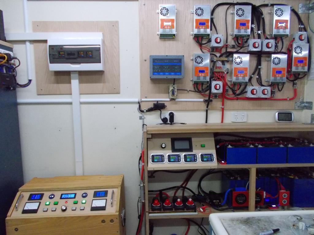 There are two output cables exiting the top of the Power case, one is a switched Inverter 240vac output (Generator) via a 10mm2 cable running to the main fuse box for powering the entire property. A separate switched output allows powering just the Emergency circuits and Shed (workshop) in the case of an extended Mains power outage under prolonged bad Solar Weather conditions. Everything is automatic via an ATS unit in the House Fuse Box and another ATS in the Shed Fuse Box, each controlled by two 45A Circuit breakers (switches) in the Inverter wall Power case. The only things to complete the system now are four heavy duty metal Battery Boxes on castors, should only take an hour or two to transfer all the cells, BMS's etc across. _ Edited 2025-08-28 08:56 by KeepIS NANO:Inverter V 8.3ks - Linux AvrDude GUI script V4.1 |
||||
Bryan1 Guru Joined: 22/02/2006 Location: AustraliaPosts: 2176 |
G'Day Keepis Eh mate I did read thru this thread where you stacked the toroids and with 3 you had enough of the primary winding to get the 240 volt output.In a couple of weeks I'm getting those 2 3500watt Aerosharps and as both are the same model I will check the ohms on each secondary and they should be very close if not the same. Saying this if the ohms test does prove it would I get away with just connecting the secondaries in parallel for 240 volt output. Regards Bryan |
||||
| KeepIS Guru Joined: 13/10/2014 Location: AustraliaPosts: 2206 |
Hi Bryan, sounds like your are going to have some fun with another DIY inverter. A quick recap to save others the boring task of reading the whole thread: The Toroids I used have a heavy single layer 93V winding around each core (first winding), thus making it easy to remove the 230Vac outer windings. Three Toroids were then stacked and the 93vac windings are connected in series giving a nominal 280vac output. The 3 stacked toroids required around 14 turns of 0G cable for the inverter input drive winding to give a regulated 235vac output from 41Vdc to 56Vdc inverter input. I use two of these three stacked toroids in the inverter, the outputs are paralleled but each three toroid stack is driven by a its own 16 FET power board, both driven by the single Nano Controller - all wiseguys hardware designs. Using series connected toroid AC windings means they don't have to be accurately matched compared to parallel stacked windings, but I see you already have the info to match yours if needed. On the question of Chokes, you can get away with the older style of chokes in low power inverters, but with AC startup loads starting around 8kW up to 24kW, and/or running continuously at 8kW to 12kW, where you would still need headroom to start other high current loads, you really need Chokes that don't fully saturate at these input power levels, were talking currents up to 700A peak in a single choke, dual chokes allow winding each choke for a lower inductance with a much higher saturation, now that is in a 48v inverter, current would be a lot higher in a 24V inverter. _ Edited 2025-08-29 10:52 by KeepIS NANO:Inverter V 8.3ks - Linux AvrDude GUI script V4.1 |
||||
| The Back Shed's forum code is written, and hosted, in Australia. | © JAQ Software 2026 |
