
|
|
Forum Index : Windmills : Working on a 10 hp motorconversion
| Author | Message | ||||
| Dinges Senior Member Joined: 04/01/2008 Location: AlbaniaPosts: 510 |
I should have more clearly described it in my previous post. There's a single-phase, single-turn wave-winding in there, the equivalent of 6 coils of 1 turn each. See image below: 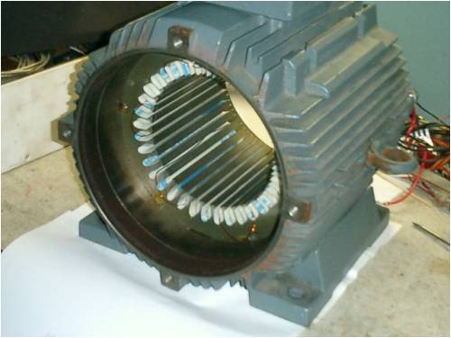
Output was 1Vac at 125RPM (actually measured 0.5Vac handcranking at 63RPM, using a stopwatch and manual counting methods); I measured it using a non-RMS DMM and as the waveshape is not a perfect sine there'll be an error. The digital scope can measure RMS-AC and show waveshape so I may use that when making accurate measurements with the VFD test setup. Here's a picture of the waveshape of the 10hp conversion (the variation in amplitude is caused by variations in RPM because of manual cranking): 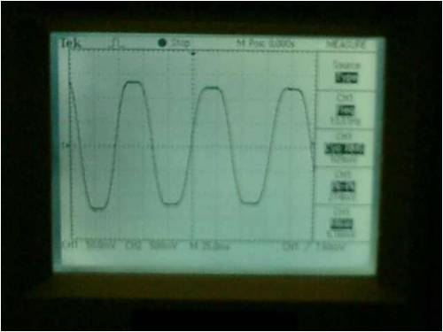
It looks moderately sinusoid, better than I expected, even though there is some 3rd order distortion which is mostly manifest as clipping of the tops of the sine. I doubt I have mentioned it here before, because I was planning on doing some more measurements and thinking/researching things before giving full information and ask this board for advice... I intend to build it for a 48V battery-charging system. I'm expecting/hoping for an output of 3-3.5kW max, but want to limit real-life generation (by furling or yawing) to about 1.5kW. I'd much rather have a continuous flow of 50-100W at low winds than the once-a-year 10kW peaks that I couldn't use anyway and needs to be dumped. I don't want to stress the generator too much. Using an over-sized generator means it'll loaf along without major load stress. I value reliability more than maximum output. The questions I have (and which I was wanting to wait asking for a little while longer... if it weren't for that nosy Oztules) are: 1) what blade diameter would you suggest/advice (I know it depends on local windsituation too, and performance of the generator itself) 2) what cut-in RPM to use for this diameter blade (most urgent design decision to be made now for turns/coil calculations) My current guess is ~4.5m and a cut-in speed of about 90 RPM (nom.48V)), but I'm open to other people's thoughts on this. Peter. |
||||
| GWatPE Senior Member Joined: 01/09/2006 Location: AustraliaPosts: 2127 |
Hi dinges, I will not speculate on harmonics, etc, or hijack this thread. The flat top of the sinisoid is caused by a period in the magnetic rotation where the coil arrangement sees a constant magnetic field. If you extrapolate what you have recorded further, you will end up with the waveform I have on my axial flux mill. One that approximates a square wave output, ie the constant voltage output approximates to 45% positive output time, and approx 45% negative output time. There is a total 10% transition period time where the output voltage reverses. How heavy do you expect your final motor conversion to be? Gordon. PS Edit, What would you consider light winds. This will give a starting point to blade size calcs. become more energy aware |
||||
| Dinges Senior Member Joined: 04/01/2008 Location: AlbaniaPosts: 510 |
Yep, that's the explanation I had in mind too, and it shows itself in the waveshape as 3rd order harmonic distortion :) I actually 'predicted' this from looking at the FEMM simulations, but in hindsight I had expected the problem to be worse than it is. 'Problem', I say, because it would be an issue when using transformers to transform output voltage. For battery charging it's not an issue of course, though I wonder if 3rd order distortion doesn't actually reduce power output, as compared to the situation where all electrical energy is present as a fundamental sinewave without distortion... A square-wave can be synthesized from only a sine fundamental and its odd-order harmonics, so your axial flux has a lot of harmonic distortion too. 'Distortion' has a negative connotation to it, but it's probably not a problem in our applications (battery charging, or using resistive loads), as long as we stay away from transformers. As for weight... the complete original motor weighed originally 65kg; this conversion will probably end up roughly the same weight, I'll measure it when it's finished. Then add a hub, blades, mechanical brake, yawing mechanism, ... and it'll be a challenge to keep it under 100kg, I fear. BTW, feel free to hijack as much as you like in my threads. The excursions are usually more interesting and educative than the original topic (in my experience). Peter. |
||||
| GWatPE Senior Member Joined: 01/09/2006 Location: AustraliaPosts: 2127 |
Hi dinges, In the case of an alternator, the shape of the output waveform in relation to harmonics content is important only with transformation. This is similar with a mathematical representation as well [fourier transform analysis and the like]. I might suggest that in my alternator that the fundamental output is a square wave. Just because this can be represented as a combination of sine waves, does not detract that fundamentally this is the waveform produced. A transformer load is probably the only load where a single sinisoidal frequency is important, as you have mentioned as well. Power transmission companies may value this property, but if DC is the ultimate goal, then I would opt for the square wave. A conductor will have the lowest loss, only when the average current and the maximum current are equal. This does not occur with a sine wave. Power generation and transmission, with a sine wave property, occurs with an efficiency penalty. My F&P mill with series caps probably benefits from a sinisoidal output. I believe there is a tranformer action occuring in this arrangement that allows this combination to produce more current. The alternator efficiency is probably lower, but the wind energy extraction of the complete system is higher, so caps will probably stay. I assume you missed this bit? Gordon. become more energy aware |
||||
wdyasq Newbie Joined: 29/07/2008 Location: United StatesPosts: 21 |
I have been following this thread with interest. I also wanted Peter and Tules to know I do try to keep up with what is happening. Ron Adventure is just bad planning." -- Roald Amundsen |
||||
| GWatPE Senior Member Joined: 01/09/2006 Location: AustraliaPosts: 2127 |
Hi dinges, I have some numbers for you to muse over. I will assume air density 1.2kg/m^3 blades approx 30% efficient alternator/rectifier approx 90% efficient The alternator is a HAWT design you require 50-100W at low winds max power say at 10m/s Low winds is pretty open ended! I would use 2m/s. A 4m dia rotor will harvest approx 2kW in 10m/s wind and approx 15W in 2m/s wind. A 5m dia rotor will harvest approx 3.2kW in 10m/s wind and approx 25W in 2m/s wind. A 6m dia rotor will harvest approx 4.6kW in 10m/s wind and approx 37W in 2m/s wind. A 7m dia rotor will harvest approx 6.2kW in 10m/s wind and approx 50W in 2m/s wind. These values are the power I would expect if a maximising system was employed. You may wish to elaborate some more re what is the intended load. The power levels and range you will need to address with loading are extreme. For a 48V nom system you are almost looking at 100's of amps. This will require some serious battery capacity. For a grid connected system, this is more than my house/grid connection capacity. You may need to look at an active power limiting system, rather than a power dissipating diversion load. I suspect that a VAWT may be a better option and what you are considering. Gordon. become more energy aware |
||||
oztules Guru Joined: 26/07/2007 Location: AustraliaPosts: 1686 |
Dinges/Gordon, I wouldn't lose any sleep about driving a transformer with a squarish waveform. I strive to get a square wave whenever I am building a PWM. Transformers seem to deal well with the square wave (forced on us by the switching characteristics of the fets.. full on or full off). I haven't noticed any woeful efficiencies from that quarter.... (unless I drive them into saturation... and then it gets ugly very quickly 
Is there something I am missing here? Dinges, If you are only after 50-100W nearly all the time then 4m prop cutting in at 90 rpm will be running is stall all the time.... except in a roaring gale. I would expect about 1-2amps in light winds, and about 5-6 in fairly strong winds. It will be absolutely silent, and almost oblivious to wind speed changes. I found that if I strangle mine by going to say 30v,(startup @84rpm) then this is what happens... if I let it out of stall (go to 48v.. start up @135 rpm), it gets very lively and puts out 100w-1kw instead of about 50-250w in the stall mode... in the same winds The only advantage of this is very reliable output without much change unless the wind picks up markedly, blades are obviously not working when set like this. It is a poor use of alternator and blades, but is extremely meek and silent and not at all scary.... the neighbours wouldn't know you had a mill. I may make some jigs and build a five or seven blade 4m to drive the mill and see how it works... no big deal with a chainsaw... no way without it though) ..........oztules Village idiot...or... just another hack out of his depth |
||||
| GWatPE Senior Member Joined: 01/09/2006 Location: AustraliaPosts: 2127 |
Hi oztules, PWM inside a faraday type screened box, is OK, but not what you would want cris crossing the country. I am sure you have heard the radio in your car have trouble with static when passing under some HV lines. This is usually the result of high power machines with some form of switching control system that radiates back through the power supply. The single frequency, typical 50Hz, simplifies transformation to compensate for loading and transmission. Safety and insulation lifetimes and RFI are also important. Gordon. become more energy aware |
||||
| Dinges Senior Member Joined: 04/01/2008 Location: AlbaniaPosts: 510 |
Thanks, Gordon & Oztules. I was thinking more of around 3m/s than 2m/s, mostly based on what Flux says (that there is very little power available in low winds to be worthwhile). Thanks for doing the math, Gordon. I have made a small spreadsheet a few years ago to calculate exactly this kind of thing; this is not my main problem. (btw, in my spreadsheet Il use a generator/rectifier efficiency of .75, and blade eff. of .25) What I do have more problems with, due to lack of experience, is guessing at proper cut-in RPM for various blade diameters. Because cut-in RPM is also a function of blade diameter, and blade diameter (i.e. power) is influenced by generator performance. But I don't have a generator of which I can measure the performance (RPM vs. power produced) yet... So it becomes a vicious circle of lack of data. The only way to cut through it is by assuming initial values for cut-in RPM (and thus blade dia) to base generator design on. Then, when the generator is finished and the power curve is measured, real blade design can start. My 4.5m/90RPM was based on one of the Dans' axial fluxes, a 15 footer, whose performance was about what I would guess would be comparable to this conversion (~2kW max). From Oztules remarks I understand however that the machine would run in stall just about all of the time. This confirms Flux's remarks that he thinks many of the Dans' turbines are stall limited. So, thanks for your replies; I think I can figure out the various powers at various windspeeds myself though, but what I really have little experience on what is the correct cut-in RPM for various sizes of blades. I.e. 4m dia blade -> cut in at ... RPM 5m dia blade -> cut in at ... RPM 6m dia blade -> cut in at ... RPM If anyone could suggest some reasonable starting numbers for that, that would be a big help. Oztules, what numbers (blade dia, cut-in RPM) does the AWP have ? I know, Gordon... 2500W at 50V voltage gives 50A... a *lot* current... I've welded with smaller currents...The power levels we're talking about here are quite large indeed. Bit like when I was drafting the rotor layout, where you only get a feeling for how large & heavy it *really* is when you are holding the finished product in your hand. It's a bit hard to imagine (for me) by just looking at a computer screen. Grid connection is not a goal at the moment but, should I ever desire to do so, I can pull 11kW from mains where I live now (3-phase 400Vac, 16A per phase), so I figure I could push a maximum of 11kW back in the grid too without blowing any fuses... 
Don't say that out loud, not when RonB is reading this thread too! 
For what generator is this, Oztules, and with what blade diameter and rated power? The AWP? Peter. |
||||
vawtman Senior Member Joined: 14/09/2006 Location: United StatesPosts: 146 |
Hi Peter Nice work so far  I would say a 30ftx4ft vawt would make that motor sing.Just don't take it for a test run in the trunk of your car I would say a 30ftx4ft vawt would make that motor sing.Just don't take it for a test run in the trunk of your car
P.s I don't think Ron hates vawts he just wants to see one produce 2kw.Kinda my goal in life
Wish you luck on the rewind and keep havin fun. |
||||
| oztules Guru Joined: 26/07/2007 Location: AustraliaPosts: 1686 |
From playing with my mill with all different voltages, some things become apparent. Nominally, it is 4M, 48v 135rpm cutin TSR 6.5. So that is the advertising blurb taken care of. What really seems to happen is interesting. @24v... the cut in must be around 70ish rpm. The mill looks to be making no speed, but puts a few amps into the batteries, almost regardless of the winds force. a small wind get 50W and a medium wind maybe 75w A strong wind maybe 5A or 120W . @48v cut in is about 135 rpm. Because it is unloaded till then, it occurs at much less wind than the calculator says. A breeze you can barely feel will touch cutin and get .5 -1 amp. It should not be anywhere near cut in at these levels, but the TSR rises to about double under no load, so we do get there. At this voltage, the thing breaks into a trot as we approach "real" startup winds. In this configuration, it will see 1-5 amps in mild winds (not enough wind that has any effect on your outdoor activities. As the wind becomes noticable, it will run between 5 and 10A and the blades will make a slight swish noise... letting me know they are cutting the air, and the lift is working. We are out of stall, but not free running. It can get boisterous at the 48v level, and push on up to 2kw in gusts and before the furl stabilises. At 60v battery, things are very different. It still starts in very mild winds, but is extremely responsive to wind movement. it can shoot up to 2-3kw in a second and back again. It is extremely lively in good wind and frightening to be next to, as it chops the air with real aggression. At 110v startup battery, it definatley needs a booster, but when it cuts in, watch out. It is a beast that rises to 4-5kw in a flash. It is a truly evil machine at these settings, and you need to be some place else, but if the wind is blowin, this is the setting to get the most out of it. Into a resistor at high winds it has seen 140v@40 odd amps. In the same winds into a 24v bank, I would see 120w. It is up to you now. So same machine, but different voltage battery bank ... makes three completely different machines. I chose 135 rpm (@48v) because I didn't want to run in as much stall as dan does, and so allow room to build a boost circuit for some fun too. At 24v, no boost necessary, the thing cuts in so early, I don't think there is any power at all to be gained before cutin. It is completely placid. You'd not know it was there from 10 feet away.... regardless of the wind it seems to run at near the same rpm. The AWP no have no figures for cutin or voltage as it runs from 200-500v into a transformer. Cut in is decided from frequency, not voltage. It is 3.6m, has TSR6-7 blades now, and is very lively... runs well out of stall and so puts out good power. So, if you want steady output without star performance, then run in full stall. (60-80 rpm cut in for 4M blades), you will never trouble the amp meter above 10 amps, but will near always be getting something around 3-5 amps.... who needs brakes or furling if the alt is strong, as it will never exceed 100rpm. (for a strong alternator that is) If you want pretty useful power with much greater rpm range, then cut in around 110 rpm may be ok, it will still be stall limited, but much more production than stalled. It will be able to break stall in a stiff wind and so needs furling to be good. If you go to 135 rpm, it will be further from stall, and be fairly lively from cutin on.very responsive and a good producer, albeit over a wide range of amps and forcing EMF. It will be capable of big power in big winds and definatley needs protection. At 200 rpm cut in, the thing is a true performer. It will benefit from a booster as in light winds it will spin, but no output without a booster. Once the wind turns up, it will make the best use of it. It will be lively, and noisy (not like a 403, but swishy). You may get up in the 3kw in gusts that you didn't think it would. This will start to match the alt to the wind curve, and performance is excellent,but you will need good furling and a strong alternator, a stout heart to stand next to it,and batteries to match or it will over drive them. Thats what I have found out so far. So pick your power (probably 4-4.5m), pick your flavour (how much grief can you stand) ie 90 rpm quiet, 130 rpm responsive, 200 rpm .. killer. This is where Flux seems to like it. He never runs in stall or near stall. If you get it a bit wrong... change your voltage/battery
..........oztules Village idiot...or... just another hack out of his depth |
||||
SparWeb Senior Member Joined: 17/04/2008 Location: CanadaPosts: 196 |
Hi again Peter, My experience will be helpful here. I really haven't had enough time to dedicate myself to writing out the MANY things I have learned over the past few months. If you can bear with me, there is a lot of experience with a) converting motors and b) matching props to the conversion, and c) doing the math, here. If only I could share more of it, I'm sure it would answer many of your questions. One question I must ask before I dive in: is that a picture of blue boy with all the wire taken out? Or is it the current 10 hp project? You haven't removed all the wire from this one yet, I hope? 
My recent 7.5hp Toshi conversion is a PERFECT 48V wind turbine generator with its original wire. I'd hate for you to have to re-wire your motor just like it was before. I'm getting the finishing touches on the analysis that is correctly predicting not just voltages, but also power output and required power input. I, too, use FEMM simulations for the starting point. As a starting point to address your immediate question about cut-in, stop using the word "stalled" right now. I sometimes see forum members writing about thir "stalled" props, but when I do the math, the TSR is somewhere around 7, and the angle of attack comes out well clear of stall. (Not criticizing anyone, here. I took two semesters of aerodynamics in college, and I'm only bringing it up because the terminology isn't useful to answer the question Peter has posed). 
It's time to start talking about "angle of attack". These airfoils need an angle of attack to produce lift. The common term "TSR" is actually the reciprocal of "advance ratio", the more correct term used for aircraft propellers. The TSR has its uses, but it hides the angle of attack. When you're prepared to delve into the details, making the conversion will help make the performance much more clear. An airfoil stops producing increased lift when its angle of attack rises beyond about 20 degrees or so. In terms of wind turbine behaviour, the reciprocal of the tangent of the angle of attack equals the TSR. TSR=6.0 1/TSR = 0.1667 atan(1/TSR) = 9.5 degrees incoming airflow angle. If the incidence of the airfoil chord is -4.5 degrees to the plane of the disk, then the blade will have an angle of attack of (9.5-4.5) = 5.0 degrees. This is an ideal place to be, because many airfoils have a maximised Lift/Drag ratio at 4 - 6 degrees. The windmill will take up an angle of attack that balances the energy going into it and the energy coming out of it. If you seriously intend to under-load your 4 meter prop, you will risk having a high TSR, because the incoming wind power will be great. Pick a wind speed where you want cut-in. You already have the RPM for the cut-in voltage. What you're left with is the diameter and TSR. Pick a TSR (first iteration) which is twice as high as the TSR you want to end up with. Now you con solve for the prop diameter. Take that prop diameter, and work out the wind power avilable. Assume 30% Cp, but also check 20% and 40% because you will not know what Cp you get before you built this. Plot a curve of Wind power for all three cases of Cp, with wind speed on the x-axis. On a separate chart, plot windspeed versus RPM. At cut-in, start the line at your cut-in RPM and wind speed. The end of the line will be at the furling wind speed and ideal TSR for your airfoil. If you draw a straight line, the TSR will be decreasing as the wind speed goes up, reaching optimum at full power. Now go back to your first graph, and make a second x-axis, below the first. On the second x-axis, write in the RPMs that correspond to the wind speeds on your other graph. This creates the Input Power curve that you need your generator to have. The power required to turn the generator is the sum of the losses and useful output power. You can quantify both: the resistance loss is R*I^2, and the iron loss is quantifiable with the pull tests you're already tried. The output power is E*I, of course. Only the iron loss is present before cut-in, so before considering the wire at all, you can determine if the windmill will cut-in the way you expect. If you find that the iron power loss is greater than the wind power available, bear in mind that you've arbitrarily picked a TSR at the beginning and maybe changing that number will correct the problem. If not, then your generator has more iron loss than can be overcome by the cut-in wind speed that you selected. Raise the cut-in wind speed until it gets the rotor to turn. Okay, the foregoing covers just picking a cut-in wind speed and TSR, but it will keep you busy for a while. In the meantime I can compose more ideas for getting the rest of the power curve to match. Stay tuned... Steven T. Fahey |
||||
| GWatPE Senior Member Joined: 01/09/2006 Location: AustraliaPosts: 2127 |
Hi sparweb, I appreciate the level of detail you have made in the above post wrt blades, but I have an observation to comment on. If you take a 3phase SCIM, of say rated 5kW. You make a comment on the motor conversion at 48V can use the original windings. The original windings would probably be rated for 415VAC star, or similar. There is an approximate 10fold reduced output voltage to run at 48V. The windings will be rated for the same current. The power output would be derated by the voltage output factor. I would make this 5kW motor as suitable as a 500-700W generator by these calcs. Maybe somehow these windings can pass more current as a generator? I would hope a 50kg motor conversion PMalternator like dinges has could do better. My AXFX alternator only weighs 8kg for 500W @ 400rpm. Have I missed something with these motor conversions re output power? They seem to be big and heavy for what power you get! I would want to up the flux transition rate and rewire, but I think the iron losses would then be a problem. Gordon. become more energy aware |
||||
| oztules Guru Joined: 26/07/2007 Location: AustraliaPosts: 1686 |
Sparweb, I suspect we are coming at this from two different backgrounds (thats apart from you knowing what your talking about, and me only watching). I can't find enough about your conversion, but I assume it is limiting at around 25 or so amps, making it around 4-500W at 350rpm or so. This is what I consider to be a high resistance stator, and because of that, it more closely resembles a sensible load for your prop, and your calculations will hold true for a greater rpm range than mine. Mine is possibly 5-10 times less resistance... so things fall apart from ideal very rapidly. A zero ohm stator will not break stall at all. It cannot increase rpm over cut in, no matter what you do... so the figures don't work past cutin, as the rpm is held constant. My machine behaves almost like that when configured as 24v. It gets up to cut in, and stalls... It barely increases rpm at all, even when the wind is at 30mph or more... it still plods along at almost startup speed, we had 80kph gusts today that nearly knocked me over, but the amps only went up to 8. Surely this means the blades are almost completely ineffectual. If not stalled then what do I call it? At 36v battery things are marginally better. It speeds up a bit more, and current may rise to 12A or more, but the blades are turning very slowly. The TSR is hopelessly behind the design TSR by a long long way, and it takes a huge gust to improve beyond that. At 48v battery, things improve, but as current passes 25A, it finds it difficult to increase, and basically "insert your own term here instead of stalling", unless a big gust turns up, but the stator pulls it back very fast. Flux calls this type of thing, as operating as stall limited. As the wind increases, the tsr falls away rapidly. I am guessing that what he means is that if the blades don't make use of the wind at or near their design TSR, then they are in some state of stall or tending towards stall. I am thinking that when tsr drops to 2 or less then it is tending towards hard stall. The difference between running at design tsr and this "stall " business can be as much as 20-30 times the power output lost...ie in winds that can drive the 24v version to 100w can drive at 60v battery bank... 3000w or more for the same winds. This is very much less likely to occur in original winding motor conversions, which is why you may not have experienced it. The otherpower use of little 2x1x1/2 magnets probably are less likely to see it also, but with bigger magnets, and lower resistances (less than 1R total), makes the prop see a brick wall if you choose cut in too low. Then you need to match the prop... but only if you want huge amounts of power. Dinges does not want that... nor do I. We can design for ideal and limit with furl only... but that is noisy and lumpy, and the unit spends a lot of time between furl and unfurl. Lots of mechanical stress. We can also derate it using the stators own resistance and deliberately mismatching it. This makes for a peaceful existence and is very soft on the machine, which is Dans preferred way... Flux likes to wring the best out of his smaller machines,and matches as best he can from the looks of it. If your machine is behaving as a perfect machine, then it will be more like Flux's units, and much less like Dans. (Dans builds low resistance machines for just this reason.) What should we call this, and have I explained it well enough to give you my perspective on it?... it's just what happens in real life (today). I also mucked up today, and let it off the batteries for a few seconds. It took off .... over 160v... a zillion rpm. I shorted the stator out, and it stopped dead in less than a second or so. ( the stator is supported by 9 2x1/4"thick chunks of steel for just such an occasion). So it is stiff enough to stop a 40mph wind at full tilt into an unloaded prop and with all the inertia of a 4m prop... this thing truly stalls these blades. (near electrocuted myself in the process) One can only guess at the amps generated for that second. I also blew up my 275Amps curtis motor controller.... went over voltage by a large margin. (was using it as a driver for the low voltage hot water heater) Spent the afternoon pulling it apart and fixing it up too.... dammit.... a few fets, totem pole drivers, a lm339 and it was better again whew.
So... what do we call it when the TSR drops in a heap?, and how on earth would you calculate for it. quizzical oztules To tired to proff read this... please forgive me. edit I notice Gordon was writing his response whist I was writing my tomb. It is interesting we came up with similar ranges of power for your unit... how close were we? Village idiot...or... just another hack out of his depth |
||||
| Dinges Senior Member Joined: 04/01/2008 Location: AlbaniaPosts: 510 |
That is the 10hp conversion with all its wire taken out, yes. The idea was to turn it into as good a generator as possible, regardless of amount of effort it took. So it was turned from a 4pole into a 12pole and now needs a rewind. And one of the goals is reducing resistance as much as possible (though I knew very little about the importance of that issue when I started out on this project). In short, a suitable cut-in (which I think was what you were thinking of) is a necessary but not satisfactory condition for a suitable generator. BTW, w.r.t. Oztules' remark about resistance (if zero, the generator won't be able to break stall), he's ignoring the fact that we can easily add and remove resistance in the line; where it is not generating heat inside the generator. Also, once the generator is wound, it's impossible to change (lower) its internal resistance; but we *can* vary line resistance. So it makes sense to have as little resistance inside the generator, and do any resistance matching (when needed) on the outside. It's even worse than that... it was originally wired for 690V in star (400V in delta). See nameplate: http://picasaweb.google.com/motorconversion/75KWMotorConvers ionBlueMonster#5207081974285014674 I've had the odd bit of aerodynamics stuffed down my throat too (nothing on props, all on aircraft aerodynamics). I recall the Cl/Cd curve for example, where above a certain AOA lift dramatically reduces and drag increases. This is what we call 'stall', and the point is pretty sharp with dramatic effects. I also notice from Oztules experiment with his battery bank that the turning point in performance (somewhere between 48-60V) is also pretty sharp and noticeable. I assume that what goes for an aircraft wingsection also goes for a turbine blade... above a certain AOA, lift *drops* (not stays the same, as you suggested) and drag increases. This is stall. As lift drops, the generator load (if it is a 'stiff' generator) is slowing the blade even more down, worsening the stall. If it weren't for this stall, we couldn't explain power actually dropping? (because output power would remain roughly the same, no matter how hard 'stalled' the blade is otherwise). I also realize that, though I may choose a cut-in RPM now, I can play around a bit with real-life cut-in windspeed by varying TSR of the blade. I was thinking more of rewinding in that case... 
Very good discussion, despite my simplistic question; still trying to digest it all. So will sit back and watch the pros wrestle...
Peter. |
||||
| SparWeb Senior Member Joined: 17/04/2008 Location: CanadaPosts: 196 |
[quote=Dinges]So will sit back and watch the pros wrestle... [/quote] I appreciate the humour, but this is supposed to be fun, so I refuse to play the "credentials" card. I've personally flown a plane in "stall" and it doesn't drop out of the sky! Okay it drops abruptly, but there is still some lift there, which you can use to continue controlling the airplane. Some airplanes are so docile when they stall, you can sit there, settling in stall, and just wallow in it. Certain aerobatic maneuvers take advantage of this. Everyone's seen the "typical" lift curve, but what you typically don't see of that curve is that it doesn't drop to zero at 20 degrees. It is abruptly reduced (on some airfoils more abruptly than others) then recovers again. By then the drag is so huge that no engine can propel an aircraft forward. On a prop, however, the effect is to slow the down the rotation. Anyway, that's not the point of what I said. Work out the TSR required for the prop of a wind turbine to be stalled, and it's less than 3, give or take some for any pre-set incidence the builder of the blade chose to add. What IS happening, at high angles of attack, is the drag is going up and up! The prop isn't stalled, it just has more energy lost to drag than can be provided by the wind. Well, here I go again, sorry. I'll step away from the blackboard now. Peter, since you're an engineer, just try to picture where the energy goes in and out, just like you did in thermodynamics class. Refine one side of the equation, and you put useful boundary conditions on the other side. Steven T. Fahey |
||||
| Dinges Senior Member Joined: 04/01/2008 Location: AlbaniaPosts: 510 |
True, there's always some lift left, but the cost of that lift has gone up dramatically (i.e. huge increase in drag). In windturbines it's a component of the lift that pulls the prop forward (i.e. cause it to rotate), whereas just about all of the drag tries to slow the blade down. So if lift goes down (even if it doesn't become zero) while drag is going dramatically up... RPM will drop a lot. The transition point is pretty sharp and so will the drop in output be. Oops...basically what I was saying in the previous paragraph. Yet you don't call this stall ? Even though L/D-ratio has gone through the floor? And the blade is 'nearly' stopped, or at least running outside of its operational range ? If that is what you mean then I think Oztules, you and I agree on everything except how to call this phenonemon; I'd call it stall, you wouldn't. I try not to think of 'just' the magnitude of either lift (L) or drag (D), but of their ratio, L/D. At and beyond stall, L/D drops a lot. I understand that, when you have established the generator curve (power vs. RPM), you can start plotting blade power curves into the same diagram (with diameter (=power) and TSR variations) and determine which combination of diameter and TSR are the best fit to the generator; where mechanical energy output of the blade must be above mechanical energy input of the generator in the operating speed range. This is what my plan was with the 500W motorconversion (though I failed to take into account that TSR is not a constant but varies over the operational range; Oztules' and your remarks have made this error in my thinking clear to me). But how one could possibly use that method for this 10hp generator...? Where absolutely nothing is known yet (apart from RPM/V perhaps)... So the boundaries would be so wide as to be practically meaningless...? To get back on topic: I think I'll go, for the moment, with a ~4-4.5m dia blade with cut-in speed at 110 RPM. A compromise between Oztules' slow/gentle 80-90 RPM and 135 RPM cut-in (48V). So, will rewind for 50Vdc @ 110 RPM. Peter. |
||||
| SparWeb Senior Member Joined: 17/04/2008 Location: CanadaPosts: 196 |
Great stuff. That looks like a target cut-in TSR of 9-13, depending on the wind speed. Lots of room to load it up as the generator begins to produce electrical current. You already have everything at hand to measure the iron loss in the generator at enough speeds to create a curve. Wrap a string around the shaft, pull with a scale, pull with constant speed, measure force and RPM simultaneously, and write down a chart of various speeds-vs-torque. I find it to be logarithmic when curve-fitting. I am interested in seeing what your curve looks like. From this, you can make the estimated generator input power curve for all speeds up to cut-in, because no electrical load is imposed below that speed. (okay, there are caveats on that statement, but generally it's negligible, and I don't expect you to connect in delta, either.) One last nail in the aerodynamics nit-picking coffin: "stall" is the term for the part of the lift coefficient curve where the slope of the line is less than zero. Flying a plane at high angles of attack, and the corresponding high drag, is called by pilots "slow-flight" or the "backside of the power curve". With respect to the blade of a wind turbine, whether it's turning slowly below cut-in, or turning a bit faster and the generator is creating power, it may well be on the "backside of the power curve", but it probably isn't stalled. If it were stalled before even cutting in, it would never work!!! It would be turning at 25 RPM in a 3 m/sec breeze. Normally, I wouldn't have tried so hard to drive this point home, but it was clearly standing in your way of understanding, Peter. Please forgive me for railroading this thread. [quote="Dinges"]...with a ~4-4.5m dia blade with cut-in speed at 110 RPM. A compromise between Oztules' slow/gentle 80-90 RPM and 135 RPM cut-in (48V). So, will rewind for 50Vdc @ 110 RPM...[/quote] Now you've chosen everything you need to work out the rest on paper. Any variation from predictions you encounter when you have finished wiring and testing, can be fixed by adjusting the prop's diameter, solidity, and TSR. Steven T. Fahey |
||||
| Dinges Senior Member Joined: 04/01/2008 Location: AlbaniaPosts: 510 |
No need to apologize for any 'railroading'. However, I've made one error in my previous response: stall doesn't begin at the angle-of-attack at maximum L/D-ratio (Cl/Cd), but at AOA at maximum Cl (lift coefficient). Important difference. Also came across this link about stall controlling windturbines, that may be interesting to some others on this forum as well: http://www.windmeup.org/2008/03/stall-control-basics.html This stall control mechanism also implies that turbine RPM remains nearly constant; which is easy for asynchronous grid-coupled generators as they synchronize themselves to grid frequency. In battery-charging generators it requires a pretty 'stiff' generator and batterybank to keep RPM nearly constant (little electrical resistance in the system). Which may make stall-control less-than-ideal for non-rewound motorconversions, with their relatively large stator resistance? Because in those generators RPM would increase much more with increasing windspeed. I think this is what Oztules was trying to say. Peter. |
||||
| Dinges Senior Member Joined: 04/01/2008 Location: AlbaniaPosts: 510 |
I have just measured more accurately the RPM/V of the 'Blue Monster' 10hp conversion. The stator now has a wavewinding (just one phase), which is the equivalent of 6 single-turn coils per phase. A few weeks ago I arrived at a result of 125RPM/V, using a stopwatch and manually cranking and counting the revolutions during 60 seconds while trying to maintain a voltage of 1Vac. Today I made a more accurate test which basically yielded the same resulting figure, 120RPM/V. Turns out there was only 4% error with the rough, manual test. Not too bad! If anyone could verify my calculations for cut-in RPM I'd really appreciate it. I've verified them a few times myself but, well, since that little incident with the 500W-conversion (where cut-in RPM ended up at 1000 RPM instead of the desired 250RPM due to a calculation error...) I'd rather not take any risks. Don't want to end up with such an unpleasant surprize on this conversion... so if anyone could take the time to verify my calculations, that would be really appreciated.
1) is the calculation of the original slotfill (as motor) 2) is the determination of the correct turns/coil for the generator (with a RPM/V of 120) 3) is the determination of the max. wire thickness, based on the results from 1) and 2) 4) is the calculation of the current density of the wire back for the old motor 5) is the calculation of the power rating as a generator, based on the same current density (27A/mm^2, which is stupidly high, IMO) as when it was a motor. Here is the scanned .jpg (600kB) of the calculations: http://picasaweb.google.com/motorconversion/75KWMotorConvers ionBlueMonster#5275614109900425122 (clicking on the magnifying glass zooms in for more detail.) Hopefully my handwriting isn't too illegible... Peter. |
||||
| The Back Shed's forum code is written, and hosted, in Australia. | © JAQ Software 2026 |
