Notice. New forum software under development. It's going to miss a few functions and look a bit ugly for a while, but I'm working on it full time now as the old forum was too unstable. Couple days, all good. If you notice any issues, please contact me.
oztules Guru Joined: 26/07/2007 Location: AustraliaPosts: 1686
Posted: 10:10pm 08 Aug 2008
Copy link to clipboard
Print this post
Hmmm Wondered how he got so much flux in the magnet
Makes sense now.
........oztulesVillage idiot...or... just another hack out of his depth
Dinges Senior Member Joined: 04/01/2008 Location: AlbaniaPosts: 510
Posted: 10:15pm 08 Aug 2008
Copy link to clipboard
Print this post
I quickly ran a simulation to compare the effects of an aluminium vs. steel rotor. I used an existing model I had of the 10 hp conversion.
The results:
with a steel rotor there is a normal flux at the tip of the tooth of 8 Wb (Weber); with an aluminium rotor it becomes 6 Wb.
With a steel rotor there's an average flux density (at the tip of the stator tooth) of 1.06 T (Tesla). With an aluminium rotor it becomes 0.80 T.
This difference is much smaller than I would have expected, I was expecting a factor two difference.
oztules Guru Joined: 26/07/2007 Location: AustraliaPosts: 1686
Posted: 10:52pm 08 Aug 2008
Copy link to clipboard
Print this post
On those figures, the steel alternator is roughly 170% the power of the Aluminium one.... so your factor of two is not toooo far away. (w=exe/r).
The steel rotor sports about 1.3 times more effective magnet flux.
Because of the square function of power to voltage, I would think:
If Al=100W, then Fe =170W at same rpm and same stator. At least I think thats the case.
.......oztules
Edited by oztules 2008-08-10Village idiot...or... just another hack out of his depth
CraziestOzzy Senior Member Joined: 11/07/2008 Location: AustraliaPosts: 152
Posted: 04:37am 11 Aug 2008
Copy link to clipboard
Print this post
I think I corrected that before I posted the comparison pictures...set the minimum to 0.1 and the max to 1.5 for comparison shots...I thought that was the right thing to do as I realised that FEMM had wild variations in the final result, unless I set a "standard" for it. But the general idea was that aluminium was not good medium to sit the magnets on. CheersEdited by CraziestOzzy 2008-08-12http://cr4.globalspec.com/member?u=25757
http://www.instructables.com/member/OzzyRoo/
CraziestOzzy Senior Member Joined: 11/07/2008 Location: AustraliaPosts: 152
Posted: 04:53am 11 Aug 2008
Copy link to clipboard
Print this post
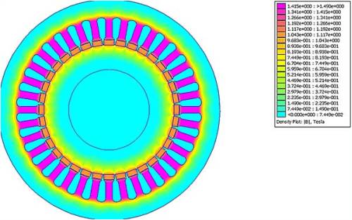
I reconstructed the stator, rotor and the magnets to actual dimensions/shape and also scaled the entire assembly to real-life and was impressed with the results.
I scaled the magnets to dimensions of magnets available from Ebay (10mm x 10mm x 30mm) that matched the stator tooth contact of 10mm.
The reason for the big difference between the picture below and others I previously posted is that the magnets are seated into the rotor by about 1mm only, rather than being fully seated and the re-design to actual real-life dimensions helped substantially (cheers Oztules for your pointer). The flux is directed to the stator where I want it.
The picture below is of a 36 pole set up with an iron rotor. I will be uploading the result of the 12 pole setup once I have decided on what magnets are available from Ebay that best suit the scale of my unit.
Not too long now I feel before I get a rotor to play with
Edited by CraziestOzzy 2008-08-12http://cr4.globalspec.com/member?u=25757
http://www.instructables.com/member/OzzyRoo/
oztules Guru Joined: 26/07/2007 Location: AustraliaPosts: 1686
Posted: 05:48am 11 Aug 2008
Copy link to clipboard
Print this post
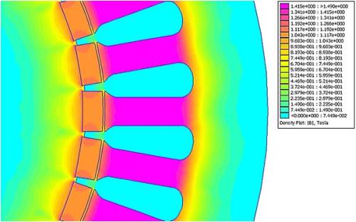
Looking very slick I must say.
I like it a lot. Your max flux is almost the full depth of the slot, you can't do much better at directing your flux than that.
In truth I think you are saturated... (which is a good thing). Dinges knows more about this than me, but I like it.
Looks like 1.4t in the slot arms, the sort of flux I only dream about in a duel axial flux.
......oztules Village idiot...or... just another hack out of his depth
Dinges Senior Member Joined: 04/01/2008 Location: AlbaniaPosts: 510
Posted: 07:02am 11 Aug 2008
Copy link to clipboard
Print this post
Looking good indeed. Not sure if the stator saturation is a good thing though, I thought it would introduce extra losses in the stator as the reversing magnetisations of the saturated teeth developed extra heat. Not 100% sure though, maybe others can chime in.
On the other hand, you haven't modelled the stator wiring as well. Under load the statorcoils will develop a reacting, opposing magnetic field that reduces flux density in the stator tooth. By how much ? No idea. I haven't tried to model this effect yet.
Would be nice if you managed to find out how to and then post it in here so I could learn how to do it too...
BTW, are you sure your dimensions are correct ? If those are 30 mm magnets and you have 36 of them, that gives a circumference of, say 30+5 =35 mm/magnet; 35*36 = 1260 mm, which gives a rotor diameter of about 400 mm. This sounds like it's much larger than the 7.5 hp motor you were talking about in your first post in this thread.
400 mm diameter rotor... My 10 hp conversion has a diameter of 130 mm... Either I'm missing something or that's one monster of a conversion you're planning to build.
Edited by Dinges 2008-08-12
CraziestOzzy Senior Member Joined: 11/07/2008 Location: AustraliaPosts: 152
Posted: 07:47am 11 Aug 2008
Copy link to clipboard
Print this post
ummm, the dimensions of the mags are 30mm deep I can't get a handle on which order to put what, just to say the area dimension of the mags here are 10mm x 10mm...the 30mm is heading away or towards you to give the 3D depth. My original rotor from the motor was 139mm in diameter. The stator inner diameter here is 140mm...I am using a 0.5mm air gap in this project. A 40cm diameter rotor sounds great though, I gotta get one of those I believe it is oversaturated too. Was thinking of using less powerful mags to compensate but figured more gutz is a good thing.
Co-incidentally, I am looking into a means of including the coils...one hell of a task to figure it out as I have only begun looking into this step. Will post my failure or success in this matter of including wiring and how to do it. Edited by CraziestOzzy 2008-08-12http://cr4.globalspec.com/member?u=25757
http://www.instructables.com/member/OzzyRoo/
oztules Guru Joined: 26/07/2007 Location: AustraliaPosts: 1686
Posted: 08:45am 11 Aug 2008
Copy link to clipboard
Print this post
Dinges,
Sometimes you need to address the animal inside of you.... more is good, even more is even better, rather than the engineer.
As I see it, the number one reason for building these things is to get low rpm, with good power density.
If we were to design it from a lossless point of view, we might just as well use ferrites, and even then not too big.
Saturation is good because we can use less turns of wire for the same emf. Saturation is bad because we introduce magnetising losses.
So like everything to do with wind, we get to make a choice. We can design for low cut-in low iron loss, in which case.... don't use an iron cored machine at all, or we stack in as much magnet as we can get our hands on, and reduce the resistance so that when we do get a bit of wind, we make some real power. A bonus is that the power curve will more closely match the prop, than the curve of the low saturation model (runaway likely)
The rewards for saturation and lower winding resistance are huge and a squared function, the losses from saturated teeth is linear (I think you proved that with a string test)... I'm voting for saturation.
I faced this problem with a seeley conversion, and as I didn't want to rewind it, I could use neo's.... but I would end up with all the iron loss with none of the resistance loss.... so I didn't go on with it. If I were to rewind to take advantage of my newfound stronger flux and larger (much larger) iron loss, it would have been a vast improvement, and useable as a normal low impedance alternator.
The other big difference with the seeley is they used low grade steel without insulation, here we are using high grade stuff, our losses are going to be a lot less severe than the seeley.... Also the frequencies we are using are fairly low, and that counts in saturation loss favour too I suspect.
So you are right, there are more associated losses, but the dividend paid out from all the extra flux more than pays off (in my mind anyway).... unless you want 4mph cut in, and a burn't stator.... like in a low t environment.
So.... Stuff in as much magnet as possible with the least turn/volt possible to get the lowest resistance possible..and I'm happy.
.............oztules (animal)Edited by oztules 2008-08-12Village idiot...or... just another hack out of his depth
Dinges Senior Member Joined: 04/01/2008 Location: AlbaniaPosts: 510
Posted: 07:19am 13 Aug 2008
Copy link to clipboard
Print this post
I wasn't exactly sure how you mounted those magnets, Craziest, but when I look at the FEMM picture, your magnets definitely don't look as 10x10 mm to me (as we look onto their ends, with the 30 mm being 'into' the screen). The height of the magnets in that image clearly do not equal their width, so the dimensions can't both be 10 mm. That's what led me to think that one dimension was 10 mm, and the other one 30 mm, hence my remark about the rotor diameter. Something's not correct in that drawing, or I am missing something.
You mean, 'if a little is good, more must be better' ? Good thing you're not a pharmacist...
I recall reading an explanation by Flux on Fieldlines about a year ago where he went into the matter of copper losses vs. iron losses in conversions, where he seemed to think too that it'd be best to try to reduce copper losses as much as possible, even at the price of increasing iron losses. I should try to refind that story .
I have another reason though for why I would now (unlike when I designed the 10 hp rotor) try to get maximum flux density too (even at the cost of saturation), and that's because the reacting, opposing magnetic flux generated by the magnets, which would lower any excess (saturating) flux by the permanent magnets. By how much ? Your guess is as good as mine...
One other thing though; in my gennies I don't necessarily want maximum output power; I don't need (don't even *want*) maximum power in a gale, it'd be useless if the batteries can't absorb it. Would need to be dumped. I'd much rather have a genny that puts out a few watts continuously, in low winds. This requires a generator with low losses. As the copper losses go up as output goes up by the square (P=I^2*R), it seems that copper losses are less relevant at low powers/speeds, with magnetic losses being a relatively larger component in the total losses (iron + copper). So it'd be best to reduce the iron losses first if one wants a generator that has least losses at low speeds/powers ? Or maybe we shouldn't try to make the motorconversion do something at which it isn't good (relatively little power at low winds due to large losses), but rather use the axial flux for that purpose ? A small axial flux with little losses for low-wind situations, combined with a lossy motorconversion to harvest wind when it really starts blowing ? Different horses for different courses and stuff. Then again, I *like* the fact that conversions are so robust, even if that comes at the price of less instantaneous power. Reliability is high on my wishlist.
Or maybe we're just overthinking it here... as it'll always work, more or less... maybe we're trying to squeeze 1-2% more performance out of a genny at the cost of a lot of thinking and design issues, and huge costs of magnets ?
Your remark about the low quality, non-insulated stator iron of the Seeley made my jaw drop.
BTW, I didn't *prove* with that 'string test' that iron losses were linear. Rather, I assumed it... in the calculations. In fact, I recall reading that there are two parts of the iron losses, both hysteresis and eddy current losses. One was linear, the other wasn't. Now, how much of the iron losses would be linear and how much non-linear ? Argh.
I think I'm becoming confuzed.
Peter. (animal-in-denial)
Edited by Dinges 2008-08-14
oztules Guru Joined: 26/07/2007 Location: AustraliaPosts: 1686
Posted: 08:24am 13 Aug 2008
Copy link to clipboard
Print this post
Hmm "You mean, 'if a little is good, more must be better' "..... he he he... if a little is good more is gooderer..er..... oh well
Moving right along...
One other handy thing with stuffing the thing full of flux and running up the stator losses....turns/volt.
It is one thing to get the resistance down, but remember, it also allows for a higher power density at a lower rpm.
What this means in the real world of compromises that make up the windmill system is... blade diam.
If you do a 10hp conversion, it is not because you wanted to generate 300w@20 mph.... no nono.. it because you wanted to develop some real power.. and possibly at lower wind speeds.
The only way to achieve this is with bigger blade sets. If you want power at less than say 12mph, you need diameter big time. more the better.
Of course if you had stuck to the stock windings with unsaturated flux densities, you would achieve this objective... or would you. If you have a 4m blade set (like my chainsaw set) then you might get 300w@12mph.... if you could generate it at 120rpm.
If you have a high winding count to get the turn/volt (because of keeping iron loss down), then you likely will have a problem generating 48v@120rpm with any real current... no problem for 300 watts, but at 20mph were only pulling 250rpm, but pushing 1.6kw into the genny, What will this look like in a high impedance alternator. (ask someone with a standard seeley, all volts and no power.
So if you design in the iron loss and accept it, you pick up on the roundabout because your rpm for getting this low wind performance can be done with bigger blades at lower rpm at lower windspeeds with a lower impedance stator. win win win... more befitting a 10hp comversion.
Both Zubbly and Methanolcat got these sorts of results on their 10hp conversions
256. rpm 103 v
351. rpm 140 v
494. rpm 198 v
654. rpm 262 v
937. rpm 375 v
So to do justice, (4kw alt I assume), we need to use 48v system so cut in is going to be around 120rpm. So in low wind we will need about 14 foot and at least 9mph to cut in.
We have 140 watts at the shaft to overcome the iron loss.. so iron loss is not the problem we thought it would be as far as low start up is concerned. If we used bigger mags, or higher grade (50) then it just gets better. If we get the rpm down too low, we can increase diameter again... and get better low wind performance. We may even generate 100w@9mph.... now that is bragging rights.
On those figures, you will need to be furling at less than 400rpm, or face a hot stator with near 6000w driving it... now the low resistance will pay dividends as well as at the low end.
Please tell me your not using a 10hp for a 10 foot blade set....
...........oztules
Edited by oztules 2008-08-14Village idiot...or... just another hack out of his depth
Dinges Senior Member Joined: 04/01/2008 Location: AlbaniaPosts: 510
Posted: 12:15pm 13 Aug 2008
Copy link to clipboard
Print this post
Oztules, you definitely manage to complicate things by dragging windturbine diameter into it as well. That's another extra variable. It's complicated enough as is, just accounting for the genny, magnetic flux and number of turns/amount of copper.
As far as the 10 hp goes, I was 'guessing' at 14 foot or a little more, but this is all pure speculation as I need a finished generator to be able to start guessing at the blade parameters. First thing to do after the rotor is finished is pick a cut-in RPM at which I want it to cut-in (48V). Then, wind the stator for this. Then, measure the generator curve (charging a battery bank).
With that information (generator curve) we can start tackling the blade parameters (how much power can the genny put out --> how large a blade do we need; at what RPM does it put nn amount of power out --> what TSR will the blade need).
About your explanation in the previous post: I can't find any obvious errors in your line of thought (that doesn't mean much though ). But I have another little thought experiment for you:
Suppose we could build a rotor with insanely large flux density. Not 1.4T but 100T, or 1000T, or even infinity T.
To have it generate 48V at a given RPM (let's say 100 RPM) it would need very few turns; perhaps just a fraction of a turn (let's say, 0.1 turn) and that we could thus make it *very* thick wire. 10 mm diameter of the copper wire ?
It's obvious in the above example that the copper losses would be extremely low, approaching zero. (ignore eddy currents in this thick copper wire; make it copper litze wire, if you want to). However, the iron losses would be very high (probably approaching infinity), due to the huge flux density. So total losses (iron+copper) would approach infinity too...
Now, imagine another extreme example where we have very low flux densities (let's say 0.001 T). We'd have very low iron losses at a given RPM (use the same RPM as in the previous example), iron losses would be approaching zero, whereas the copper losses would be very high due to the need for many many turns of extremely fine wire. The total losses would be dominated by the copper losses and would be very high too, approaching infinity as flux density approaches zero.
It's my idea that somewhere in between these two extreme cases (near-zero flux density and near-infinity flux density) there must be an optimum flux density where the total losses (iron + copper) are at a minimum.
Where this optimum lies exactly ? I figure that's the million dollar question. Is it at 0.5 T? 1.4 T? 2T ? 10 T ? At another (totally impractical) flux density ? Your guess is as good as mine. But there should be an optimum somewhere, as I've shown above, so it's not simply a case of 'more is better' (your original premises). There comes a point at which more isn't better. Perhaps this point lies way outside the range of flux densities we're normally messing with (0-2T). (if the optimum is at, say, 100T, then it's obvious we should do as you suggest and strive for as large flux densities as practically possible, even at the price of saturating the stator, if it reduces total losses).
I'll admit, the above line of thought is a bit outside the realm of the practical but thinking in such extremes helps (at least, it helps me) to figure things out.
All this thinking has given me a headache.
Peter.
Edited by Dinges 2008-08-14
GWatPE Senior Member Joined: 01/09/2006 Location: AustraliaPosts: 2127
Posted: 12:40pm 13 Aug 2008
Copy link to clipboard
Print this post
hi oztules,
I found the best solution to the problem if increasing the flux density was to remove the iron from the equation.
Gordon.
become more energy aware
oztules Guru Joined: 26/07/2007 Location: AustraliaPosts: 1686
Posted: 12:44pm 13 Aug 2008
Copy link to clipboard
Print this post
Dinges, you forgot to factor in infinite free power source, and infinite diameter... do the exercise again and see where you end up for maxpower.
Ok so infinity does not work at all because in theory sq, cube and linear functions will all meet somehow.... my mind swims at this point..so
Lets stick to real numbers, but very big still.
If we halve the cut in, we can double the diameter which squares the input power which just gets better when we do it again and again and again. ie linear decrease in cutin from increased T for squared increase in power.
So it would seem that if we increase our T, then we decrease our rpm and increase our potential wind cross section which delivers a squared result.
It is precisely that we have near infinite wind power available, that we can increase the diameter every time we increase T..... copper losses are squared the other way...can't win like that.
On a practical note, if we increase the T to maybe 4-5t, perhaps we don't need to decog. The saturated iron and the air gap may approach equal attraction/repulsion.
If we fix the diameter, then it would be a whole new ballgame, where there would be a best flux verses loss equation.
But because we can increase diam to offset losses at a greater rate than we incur them....what do you reckon.
...........oztulesEdited by oztules 2008-08-14Village idiot...or... just another hack out of his depth
oztules Guru Joined: 26/07/2007 Location: AustraliaPosts: 1686
Posted: 12:49pm 13 Aug 2008
Copy link to clipboard
Print this post
Gordon..... I believe thats cheating.... and a bit difficult for a motor conversion. Village idiot...or... just another hack out of his depth
Dinges Senior Member Joined: 04/01/2008 Location: AlbaniaPosts: 510
Posted: 01:13pm 13 Aug 2008
Copy link to clipboard
Print this post
No I didn't forget that, but I should've explicitly stated 'for a given power' in the previous examples, as I did for the RPM. Ceteris paribus, all else being equal.
They all meet at zero. But infinity squared is still infinity...
No problem with that, was what I was doing anyway in the previous examples.
There you go complicating things again by dragging aerodynamics into it. Blade diameter (perhaps even TSR later ?) Let's try to focus on *just* the generator for now. Fixed RPM (say, 100), fixed mechanical shaft input power (say, 100 W), fixed voltage (say, 48V). Let's just vary flux density for the moment. No more, no less. Maybe we can complicate things later on when we've figured this part out...
You're dragging into it another variable, blade diameter. This complicates matters. Let's just assume that we put 100W mechanical energy into the generator; in my extreme cases ALL of this mechanical energy would be converted either to iron loss (100W of heat into the stator at infinity flux density) or copper loss (100W of heat into the stator windings).
Took me awhile to understand this, but yes, if you keep increasing blade diameter then you're right. But, as I said before, that's introducing more complexity into the problem. Let's just focus on the genny without dragging the can-of-worms known as 'aerodynamics' into it and by keeping shaft input power contant, just for the sake of the argument.
Heh. Good point. Not very relevant to the problem at hand (what's 'optimum' flux density, if an optimum even exists (which I think it does)), but still an interesting observation. Will have to keep that in mind for future thought. High flux-densities shouldn't be too hard to realize with electromagnets.
That's my idea. Let's keep this simple by only having one variable, i.e. flux density. I'm just a dumb Dutchman. It's hard enough for me to count to 20 without taking off my shoes...
Darn Oz. Just when I'm having a ball you have to throw such simple practicalities as 'just increase blade diameter a tad to compensate for the losses' in my face... And you're of course absolutely right.
...But with that argument any quest for efficiency becomes meaningless; in that line of thought, the solution for too high wire resistance between the genny and battery wouldn't be to reduce the resistance of the wire by installing thicker wire, but to just make the genny another tad larger to compensate for the losses. Lousy conversion efficiency of the batteries ? Install a bigger battery bank and an even larger genny. Incandescent lights are ineffecient, so why replace them with CFL if we can just install a slightly larger batterybank and a larger genny...
With the line of reasoning you gave ('increase blade diameter a little to compensate for inefficiencies') one can put an immediate end to ANY discussion about the quest for maximum efficiency, as the one cure-all answer is 'just make your system a little bigger'.
So, Oztules... Time to confess... what *really* is your opinion on efficiency...
Edited by Dinges 2008-08-14
GWatPE Senior Member Joined: 01/09/2006 Location: AustraliaPosts: 2127
Posted: 12:36am 14 Aug 2008
Copy link to clipboard
Print this post
As a question, how do you alter the iron stator dia in a rebuild.
Gordon.
become more energy aware
GWatPE Senior Member Joined: 01/09/2006 Location: AustraliaPosts: 2127
Posted: 12:40am 14 Aug 2008
Copy link to clipboard
Print this post
Hi dinges,
what we probably should be considering in this thead is electromotive efficiency.
Gordon.
become more energy aware
oztules Guru Joined: 26/07/2007 Location: AustraliaPosts: 1686
Posted: 02:46am 14 Aug 2008
Copy link to clipboard
Print this post
Gordon,
"As a question, how do you alter the iron stator dia in a rebuild. "....answer.. choose a different victim.
The only other way of changing dynamics is to put the coils on the outside of the stator and the magnets around them there like this: (courtesy of Flux)
and then build a drum for the magnets like this: (Flux again):
Beyond that I don't see any other obvious way apart from cut and paste each plate (cut sections out and alter the diameter) and re-assemble. difficult but possible.
.........oztules Edited by oztules 2008-08-15Village idiot...or... just another hack out of his depth
oztules Guru Joined: 26/07/2007 Location: AustraliaPosts: 1686
Posted: 03:21am 14 Aug 2008
Copy link to clipboard
Print this post
Efficiency... interesting concept you have there Dinges.
In windmill work, almost anything cobbled together with some magnets and some wire will generate something. The trick is to do it economically in both space, material and lastly dollars.
Normally efficiency is of importance because we have a set amount of energy to drive the system, so economics of power out versus power in is of absolute importance. However, even in important devices such as internal combustion engines with their terrible efficiencies,.. they offer a degree of useability that so far has easily outweighed efficiency, which comes out poorly.
But the usefulness of the device allows us to grin and bear it to a large extent.
In wind, it is much more complicated, as changing one component necessitates changing another. First we need to decide on how much power we want, and having decided that there is only one efficiency that is worthy of interest... and that relates to resistance.
It is simple simon stuff to make a stator of any voltage for any rpm.... it is a different thing extracting power that we want from this position.
I have no real interest wondering what power in verses power out is, as it is only for bragging rights. Looking at the bigger machines here (just big induction motors with massive gearboxes), they generate huge amounts of power at terrible efficiencies, but apart from the tower and supporting equipment, they are cheap as nuts to make, and produce multi kilowatts out.
Now we will lose lots and lots through the gearbox, but who cares, we lose lots and lots through the magnetising currents in the stator too.. but what the heck, we get lots of power out economically.
It could be done more efficiently with a huge permanent magnet dual axial flux with huge grid tie inverters. You should realise good in/out efficiency figures, but it would cost the earth, and not be as reliable.... and all you will save is a few feet of prop for all your effort... whoopee.
The only thing to be mindful of is matching the prop to whatever you decide to generate the power with..... and the only consideration with what you generate the power with is copper loss... iron loss can be compensated for cheaply, and a cooling fan can paper over the losses. I see no reason to worry how much wind we use up in the process.... unless I was supplying the wind... then I would see it your way.
I understand that in power generating equiptment, the goal of the designer is to make the copper loss in the same ballpark as the iron loss... and this tends towards the most effecitive use of input power.
.............oztulesEdited by oztules 2008-08-15Village idiot...or... just another hack out of his depth
Page 3 of 4
Print this page
The Back Shed's forum code is written, and hosted, in Australia.