
|
|
Forum Index : Microcontroller and PC projects : Programmable calculator on Pico DIY
| Author | Message | ||||
| zeitfest Guru Joined: 31/07/2019 Location: AustraliaPosts: 692 |
The "clicky button" route has not gone well   / /They are way too clicky/noisy ! Apart from the click annoying everyone including me within earshot over a large area, they also numb/damage the fingers after moderate use. The pcb seems to act as a sounding board making it worse. Adding logos/foam pads made the sound louder (??!) and attaching them was unreliable too. Also the round active button-press rotates within the switch, so a logo "+" rotates to look like a "x" which is not good. I also tried a membrane on top of the switches, it works ok but does not muffle the click.  Undeterred I have found a pushbutton that still has a definite action but is basically silent. Cheap too. Of course, the pinout is different to the usual 4 pin switch...so needs another pcb ... The question is, is a two-pad smd pushbutton going to be fastened to the pcb robustly enough to stand up to keypad use. Dunno. |
||||
| Mixtel90 Guru Joined: 05/10/2019 Location: United KingdomPosts: 8965 |
Would these silent ones be of interest? AliExpress same switch in 4-pin They are 8x8, so a little more finger space. . Edited 2024-12-09 17:53 by Mixtel90 Mick Zilog Inside! nascom.info for Nascom & Gemini Preliminary MMBasic docs & my PCB designs |
||||
| zeitfest Guru Joined: 31/07/2019 Location: AustraliaPosts: 692 |
Great ! They look very useful, I will see if I can wrangle the existing pcb a bit to suit the 8x8 mm. |
||||
| Mixtel90 Guru Joined: 05/10/2019 Location: United KingdomPosts: 8965 |
You might want to try a couple first. The actuator isn't quite as rigid as a normal switch. Absolutely silent though. :) Mick Zilog Inside! nascom.info for Nascom & Gemini Preliminary MMBasic docs & my PCB designs |
||||
| zeitfest Guru Joined: 31/07/2019 Location: AustraliaPosts: 692 |
I tried these and they are good, they are smd with two pads though with less spacing for the pcb traces. One hassle was that the 4-pin button switches included internal connections as two sets of two pins. Kicad schematics didn't really accept that so I bypassed the schematic and just did the pcb layout directly using the switches as wire links, so that is going to need rework. |
||||
| Mixtel90 Guru Joined: 05/10/2019 Location: United KingdomPosts: 8965 |
I say those little switches and almost bought some, but I was saving money and took them out of the basket. Trust KiCAD not to have a model for the most common tactile switch. :) I can't really believe that. 4-pin is probably the easiest arrangement to multiplex. Mick Zilog Inside! nascom.info for Nascom & Gemini Preliminary MMBasic docs & my PCB designs |
||||
| zeitfest Guru Joined: 31/07/2019 Location: AustraliaPosts: 692 |
Reworked the pcb to use the silent push buttons. 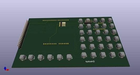 As before, the tca8414 module plugs in and provides i2c sockets. The kicad view includes some pins on the front which will be left off in use. The 6x5 area should be useful separately as a keypad too so I have created a cut-down with just that. Maybe the 'mites can use a I2C keypad ? |
||||
| zeitfest Guru Joined: 31/07/2019 Location: AustraliaPosts: 692 |
The new pcb is working well, and is quiet  . .Tidying up the I/O (read and write) has had a benefit, as it happens the input fields now accept csv input from the keypad as data so multiple values can be input at once, it meant I had to add a "comma" button to the keypad, but much more convenient !. Adding formatted I/O has been a real cow but worth it. Getting back into it after xmas snooze |
||||
| zeitfest Guru Joined: 31/07/2019 Location: AustraliaPosts: 692 |
After a fair slog.. the software I/O is now fairly conventional and can read/write files well, eg the following accesses two files, reading from one and writing to the other. It looks like simultaneous operation is ok ( quibble, dodge, weave etc ) which was a design aim. That adds a very powerful processing ability. It includes csv format i/o for spreadsheets etc.There are small bugs yet eg the (ed) float format is default still but I am well pleased that it's a goer. >R Running PROGRAM testread INTEGER*4 x REAL a DOUBLE b INTEGER*1 c INTEGER*2 d INTEGER*4 e CHARACTER*1 f CHARACTER*7 rinso 75 FORMAT (F4,F4,I1,I2,I4,A1,A7,/) 85 FORMAT (A1,A1,F4,F4,I1,I2,I4,A1,A7,/) OPEN "/Output.txt" WRITE OPEN "/Inputfrm.txt" READE (6,75) a, b, c, d, e, f, rinso WRITE (8,75) a, b, c, d, e, f, rinso READE (6,85) f, f, a, b, c, d, e, f, rinso WRITE (8,75) a, b, c, d, e, f, rinso END \ open file write open file read readin readin OK ... Input file content : 1.112.223445555MFlubber 9.998.887664444TGrungit Output file content: 1.1100002.2200003445555MFlubber 9.9900008.8800007664444TGrungit Edited 2025-02-12 13:06 by zeitfest |
||||
| zeitfest Guru Joined: 31/07/2019 Location: AustraliaPosts: 692 |
After mods and the right format spec ..  75 FORMAT (F4,F4,I1,I2,I4,A1,A7,/) 85 FORMAT (F4.2,F4.2,I1,I2,I4,A1,A7,/) OPEN "/Nuout.txt" WRITE OPEN "/Inputfrm.txt" READE (6,75) a, b, c, d, e, f, rinso WRITE (8,85) a, b, c, d, e, f, rinso READE (6,75) a, b, c, d, e, f, rinso WRITE (8,85) a, b, c, d, e, f, rinso END \ Iput file 1.112.223445555MFlubber 9.998.887664444TGrungit Output file 1.112.223445555MFlubber 9.998.887664444TGrungit |
||||
| zeitfest Guru Joined: 31/07/2019 Location: AustraliaPosts: 692 |
The csv concurrent file i/o is a goer. The files are declared as csv. The * specifies default formats for the individual fields which can be overridden by a declaration and so on. As a test this reads a line of csv file data into variables and then writes/appends it to another file in csv format, then repeats. As a check the values are printed on screen so that I can make sure it works ok !! It also tests the implied-list handling. PROGRAM testread INTEGER*4 n(5), x OPEN "/RepImp.txt" WRITE CSV OPEN "/InImp.txt" READONLY CSV READE (7,*) ( n(x), x = 1, 5 ) WRITE (8,*) ( n(x), x = 1, 5 ) PRINT n(1), n(2), n(3), n(4), n(5) READE (7,*) ( n(x), x = 1, 5 ) WRITE (8,*) ( n(x), x = 1, 5 ) PRINT n(1), n(2), n(3), n(4), n(5) END \ >R Running ... open file write open file read readin 54321 readin 246810 OK ... Input file on 7. InImp.txt is : 5,4,3,2,1 2,4,6,8,10 Output file on 8, RepImp.txt is : 5,4,3,2,1 2,4,6,8,10 |
||||
| zeitfest Guru Joined: 31/07/2019 Location: AustraliaPosts: 692 |
Added a small graph display, just 100x200 pixel but good for a quick optic. It is fed an array of y value integers scaled 0 to 100, assumes x 0-100 integer inclusive scale wide so 101 values - needs some tweaks yet. Eg this calculates sin values for three cycles and displays it. >R Running PROGRAM steffi DOUBLE x, y INTEGER*4 j, yarts(101) x = 0.0 DO j = 1, 101 y = 50.0 + 50.0 * SIN(x) x = x + 0.0628 * 3.0 yarts(j) = IFIX y END DO GRAPH yarts(101) PRINT "finish" END \ Edit - replaced photo 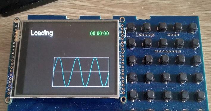 Edited 2025-03-04 10:16 by zeitfest |
||||
| zeitfest Guru Joined: 31/07/2019 Location: AustraliaPosts: 692 |
Also added access to the analog-digital converter, just as a basic nicety ( we can't have graphs without measurements now, what in the world rant etc )Just using as a keyword in the first instance eg ADC0 gets the value from the A/D measuring on analog pin 0. Running PROGRAM sousvide INTEGER*4 i, j(101) DOUBLE a DO i = 1, 101 a = DBLE( ADC0 ) / 1024.0 j(i) = IFIX ( a * 100.0 ) END DO GRAPH j(101) END The screen result from above shows about one and half cycles of background humm at 50 Hz as present on my thumb so that is the loop repeating at a bit over 3kHz by default. 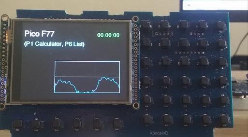 The A/D can be operated much faster, the loop is not intended for speed, but it is ok for the time being. I think the A/D is being switched on and off each loop which is not optimal. OK for a "calcometer" so far Edited 2025-03-04 18:16 by zeitfest |
||||
| zeitfest Guru Joined: 31/07/2019 Location: AustraliaPosts: 692 |
Now I realize the quiet push-buttons used are the ones suggested by Franknfurter, excellent idea thanks !!! A problem with DIY keys is putting a logo on each. I tried labels/glue/foam/etc but the results were not robust and didn't look very good. However I noticed a photo service shop would print photos onto a "card" which turned out to be laminate. It has two thin aluminum sheets bonded to a plastic core, the photo is scanned and printed on it, the ink is light-cured and robust. Very easy to work with and not expensive. So I got the key logos printed onto a "card" and and stuck them on the keys with bonding adhesive, the keys destruct before the logo can be separated. Needs a suitable case but looks good so far. 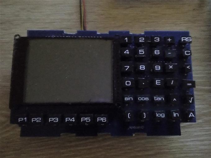 Also added a "line continuation" , ie so an equation can be continued on the following line. Otherwise the equation had to be split which was lousy. eg the equation C C el = ASIN ( SIN ( dec ) * SIN ( lat * rpd ) + C COS ( dec ) * COS ( lat * rpd ) * COS ( ha ) ) C had to be split and reconstituted temp = COS ( dec ) * COS ( lat * rpd ) * COS ( ha ) temp = temp + SIN ( dec ) * SIN ( lat * rpd ) el = ASIN ( temp ) but now the standard continuation process is used instead el = ASIN ( SIN ( dec ) * SIN ( lat * rpd ) + + COS ( dec ) * COS ( lat * rpd ) * COS ( ha ) ) That just about finishes any additions, now just the debugging Edited 2025-04-02 00:26 by zeitfest |
||||
| Volhout Guru Joined: 05/03/2018 Location: NetherlandsPosts: 5994 |
Hi zeifest, At the moment you are using I2C for keyboard and lcd. Since the development is almost complete, are you interesten in a simplified version where the pico does It all. Key scan, and direct drive the lcd. And a low power circuit, so It can sleep weeks ad month until you press the ON push button. Volhout PicomiteVGA PETSCII ROBOTS |
||||
| zeitfest Guru Joined: 31/07/2019 Location: AustraliaPosts: 692 |
Is there a project you have at the moment, post some info ? The keypad i2c/TCA8418 is good and lives in the event loop ok, and also ties it in to supplier chains. But the display via i2c is pretty slow so an alternate path would be good. Maybe a second pico to drive the interface.. Driving a moderate display can be an iceberg. Updating a few fields from a program is straightforward but maintaining state (so that the data is consistent) can be tricky. ATM it is driving a 3.2" display, maintaining state of data fields etc, but it is overkill for a calculator. In fact I looked at a cut down version with a 16x2 lcd, but the lcd needed 5v though. But it would have fitted nicely on a cheap 4"" pcb ... It is heavily based in open-source and Arduino so there is no commercial direction. ed - A pcb with pico with 16x2 lcd /sd micro /i2c probably exists out there already (?) More thinking to do Edited 2025-04-02 21:35 by zeitfest |
||||
| zeitfest Guru Joined: 31/07/2019 Location: AustraliaPosts: 692 |
Although technically it is not part of the f77 standard, I have added a "WHILE" loop construct as it seems that is a Good Thing for structured programming yada yada.. Thought it would be simple...eeesh...  Anyway it is working. For a calculator it is probably overkill, it is easy to get stuck in a loop without trace, so I may restrict it a bit. Haven't used "while" much so I hope it is right . PROGRAM whiles INTEGER*4 k, m, n PRINT *, "Start" k = 0 m = 0 n = 0 WHILE ( k < 2 ) THEN WHILE ( m < 2 ) THEN WHILE ( n < 2 ) THEN PRINT *, "k=", k, " m=", m, " n=", n n = n + 1 END WHILE n = 0 m = m + 1 END WHILE m = 0 k = k + 1 END WHILE PRINT *, "Fin" END ... Start k=0 m=0 n=0 k=0 m=0 n=1 k=0 m=1 n=0 k=0 m=1 n=1 k=1 m=0 n=0 k=1 m=0 n=1 k=1 m=1 n=0 k=1 m=1 n=1 Fin OK |
||||
| zeitfest Guru Joined: 31/07/2019 Location: AustraliaPosts: 692 |
Tried a version with 16x2 lcd and a 6x6 keypad...works ok so far (in Salvador Dali air-wired mode ) but the lcd is a bitcramped. Less cost though. I think a bare bones version with a smaller 6x5 keypad would fit on a 4" pcb. [showing the pico, sdmicro adapter, keypad and 5v booster with a red led] ed- changed backlight to 3.3v supply instead of 5v, wire is behind lcd. replaced photo. 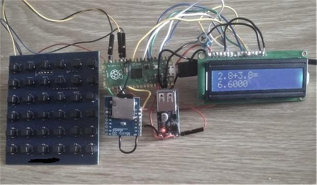 I'll post the keypads if there is interest, they are not complex but might save some hack work Edited 2025-07-07 13:19 by zeitfest |
||||
| zeitfest Guru Joined: 31/07/2019 Location: AustraliaPosts: 692 |
maybe a "budget" model ?! (on a 4" pcb) 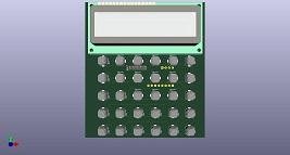 |
||||
| Volhout Guru Joined: 05/03/2018 Location: NetherlandsPosts: 5994 |
Hi Zeitfest, You mentioned the LCD backlight is now driven from 3V3. In case the whole LCD can work from 3V3 you can remove the 5V convertor. Apply 3V (2 x AAA call) to the Vsys pin of the Pico, and it will generate 3V3, even when the batteries drain to 2V. Volhout PicomiteVGA PETSCII ROBOTS |
||||
| The Back Shed's forum code is written, and hosted, in Australia. | © JAQ Software 2026 |
