
|
|
Forum Index : Microcontroller and PC projects : One for the amplifier experts
| Author | Message | ||||
| vegipete Guru Joined: 29/01/2013 Location: CanadaPosts: 1182 |
Don't give up on the PWM driven H-bridge, just don't generate the PWM in the Picomite. Instead, feed the SPIDAC output to one side of a comparator (op-amp.) Feed a triangle wave of you chosen frequency to the other side. The output from the comparator will be your PWM signal, with 50% duty cycle when the analog input is 0 volts (assuming you've got all the offsets etc correct.) Visit Vegipete's *Mite Library for cool programs. |
||||
| PhenixRising Guru Joined: 07/11/2023 Location: United KingdomPosts: 2008 |
@Volhout Not the CMM2...Only the PIO can handle the encoders. 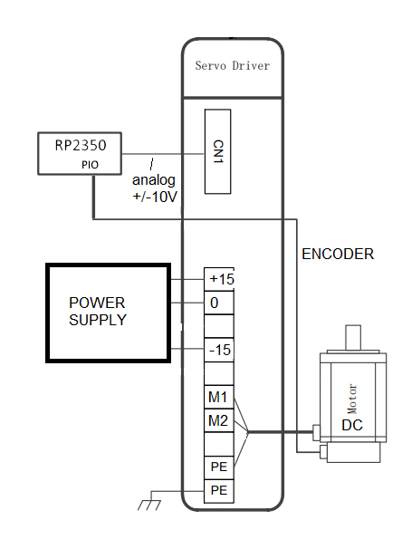 The drive on the machine feeds the encoder signal to the drive and the drive has an "emulated encoder output". The PicoMite (in my case) will handle all aspects of motion control, so the emulated encoder outputs will feed the PIO. Thanks for all the help, guys but I've been in touch with two suppliers and I'm just gonna go-ahead and get their miniature drives/motors. They have the same features as the bigger units and some of those might be useful in other applications.  |
||||
| Mixtel90 Guru Joined: 05/10/2019 Location: United KingdomPosts: 8965 |
Sometimes that's the best approach. You tend to get more meaningful results when using more similar equipment. Mick Zilog Inside! nascom.info for Nascom & Gemini Preliminary MMBasic docs & my PCB designs |
||||
| PhenixRising Guru Joined: 07/11/2023 Location: United KingdomPosts: 2008 |
Revisited because I came across this: 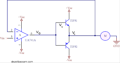 From this site Only problem I see from my attempt at using the circuit simulator applet is that the 741 opamp can only provide ~25mA which means that I won't be able to drive the transistors sufficiently. What's the best way to boost this, an alternative opamp or a transistor? |
||||
| Volhout Guru Joined: 05/03/2018 Location: NetherlandsPosts: 5994 |
Hi Phenix, These are opamps (accurate, low offset, high open loop gain, etc..) OPA541 (Texas Instruments), sells for 20 euro's. +/-40V max 10A output opamp. OPA549 (Texas Instruments), around same price, +/-30V max 8A These are audio amplifiers (maybe not that low offset, but much cheaper) TDA7294 (ST Microelectronics), +/-40V 10A max. Around 4 euro. LM4766 (TI), +/-30V 4A max LM3876 (TI), +/-42V, 6A max, around 6 euro LM3886 (TI), +/-42V, 11A max, around 4 euro You can treat these as normal opamps in your motor drive application. One thing some audio amplifiers do not have is a large common mode voltage range. That means that you will have to give the amplifier some gain (i.e. 10x) In that case you drive the amplifier with +/-1V to output +/- 10V to the motor. Volhout Edited 2025-03-21 02:36 by Volhout PicomiteVGA PETSCII ROBOTS |
||||
| Mixtel90 Guru Joined: 05/10/2019 Location: United KingdomPosts: 8965 |
And so the original post comes round again. Same circuit but with component values. :) I really hate the idea of using linear control for motors. The above circuit has two major problems: The output transistors will get seriously *hot* with any load. The torque will be poor. The latter is because torque is proportional to the applied voltage and this sort of control changes the voltage across the motor so the torque is bad at low speeds and improves as you speed up. To make things worse, it's inefficient as far as motor voltage goes because it's a half bridge. A full bridge puts the motor across both supply rails. This gives it maximum voltage but also balances the load on the supplies. PWM uses a constant voltage so the torque at low speed is far better. I understand that you don't want to use it because of reaction time issues, but perhaps you are pushing this too far? PWM with a lighter motor that's geared down would be far more effective than a heavy armature. If you insist on doing it this way then you could change the output transistors for darlington types, which have a far smaller base current. There is also a configuration called compound darlington which uses PNP/NPN as shown but followed by a NPN pair, which would be better for power handling as large PNP devices are harder to get and more expensive. You may need some serious heatsinks. :) Mick Zilog Inside! nascom.info for Nascom & Gemini Preliminary MMBasic docs & my PCB designs |
||||
| PhenixRising Guru Joined: 07/11/2023 Location: United KingdomPosts: 2008 |
Oh heck, I hadn't realised that  It's not for a real application, it's for a test rig. Can't use the PicoMite's PWM because: My PID loop + velocity profiler runs in a 1ms interrupt BUT our PWM takes > 1ms to update and so I am using an SPI DAC to produce the +/- 10v motor command signal. |
||||
| PhenixRising Guru Joined: 07/11/2023 Location: United KingdomPosts: 2008 |
@Volhout Thanks, Harm. Yeah I was looking at the OP541 but that's an interesting list  |
||||
| Mixtel90 Guru Joined: 05/10/2019 Location: United KingdomPosts: 8965 |
"Test rig" might still have 2A motors. At half speed the dissipation is shared between one transistor and the motor so with a 12V supply (only one is being used) that's 12W of heat to be dissipated. It will probably be more as heatsinking is never 100% efficient. Obviously, if the motor needs more current the dissipation will be higher. Mick Zilog Inside! nascom.info for Nascom & Gemini Preliminary MMBasic docs & my PCB designs |
||||
| PhenixRising Guru Joined: 07/11/2023 Location: United KingdomPosts: 2008 |
@Mixtel90 Linear amps for motors are definitely a thing.. |
||||
| Mixtel90 Guru Joined: 05/10/2019 Location: United KingdomPosts: 8965 |
I didn't say that it wasn't possible, just that there are disadvantages. e.g. the reduction in torque at low output voltage can be compensated for by including current control in addition to voltage control. It may be using voltage control to adjust the speed and holding it constant by using constant current control. Everything becomes far more complex than the simple amplified op-amp circuit. You can't get rid of the heat problem in a linear output stage. It's inherent in it being linear. The best you can do is to get the heatsinking as efficient as possible. If I could design a box like theirs I'd make sure I was charging their sort of prices. :) Mick Zilog Inside! nascom.info for Nascom & Gemini Preliminary MMBasic docs & my PCB designs |
||||
| stanleyella Guru Joined: 25/06/2022 Location: United KingdomPosts: 2807 |
I bought 2 of these but no cpu control https://www.ebay.co.uk/itm/394610279715 |
||||
| PhenixRising Guru Joined: 07/11/2023 Location: United KingdomPosts: 2008 |
That's where the integrator of the PID comes into play (encoder feedback). The shaft will maintain position until the disturbance is sufficient to overpower the maximum available current (torque). |
||||
| phil99 Guru Joined: 11/02/2018 Location: AustraliaPosts: 3323 |
Analogue controlled PWM has already been mentioned. You don't need to build it if you use a Class D audio amplifier module. See AE or ebay, hundreds to choose from. Just remember to divide the claimed output power by 2 or 3. PWM frequency is usually 150 to 300 kHz, efficiency 85% - 95%, 20kHz frequency response so there won't be much time lag between Vin and Vout. Edited 2025-03-21 07:04 by phil99 |
||||
| PhenixRising Guru Joined: 07/11/2023 Location: United KingdomPosts: 2008 |
Yes, I like this approach because it is similar to my industrial servo drives; analog in, PWM out. Hmmm, I actually have a few of these, not even unboxed. Would they work? 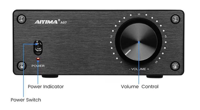 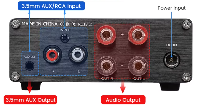 |
||||
| phil99 Guru Joined: 11/02/2018 Location: AustraliaPosts: 3323 |
A stand-alone amplifier probably has input coupling capacitors so may need some mods for DC input. When the input is DC coupled its power supply may need to be isolated from the input ground. Eg a separate plug-pack. Edited 2025-03-21 08:18 by phil99 |
||||
| Volhout Guru Joined: 05/03/2018 Location: NetherlandsPosts: 5994 |
Sorry Mick, PWM shines when it comes to efficiency. But it is worse than you description. Assume the motor efficiency is 100% (it is not, but assume it is). Assume a 12V motor, and a 15V supply, linear output driver. If you want to supply 25 watt of mechanical power at it's maximum speed (12V), the current is 25/12=2.08A, and the linear driver dissipates (15-12)*2.08 = 6.25 watt. In case you want to supply 25 watt of mechanical power at a lower speed (say 50%), the motor is suplied with 6V at 4.16A (=25 watt). The driver dissipates (15-6)*4.16 = 80 watt. For much lower speeds (i.e. 25%) it gets exponentially worse. 25 watt at 3V motor voltage is 8.3A, and the driver dissipates 183 watt... for 25 watt output. For a PWM drive the power dissipation in the driver in these same situation are far below 10 watt in all above cases (100%/50%/25% speed). I am sure you can get below 2 watt when carefully designing. And this also refelects on the power supply. In the 25% speed linear driven motor, the power supply needs to supply 183+25 = 208 watt at 15V = 13.8 amps. In case PWM the power supply is rated 25 watt + 10 watt = 35 watt (15V 2.2 amps), but should be able to supply peaks of 8.3A (extra buffer capacitors at the output). Volhout P.S. class-D audio amplifiers have circuits that cancel DC build up in the output, and often have AC coupling at the input. Although the electronics are suitable, it may be difficult to remove these DC canceling circuits. Edited 2025-03-21 17:37 by Volhout PicomiteVGA PETSCII ROBOTS |
||||
| Mixtel90 Guru Joined: 05/10/2019 Location: United KingdomPosts: 8965 |
Now you know why I don't design linear motor drivers, Harm. :) Mick Zilog Inside! nascom.info for Nascom & Gemini Preliminary MMBasic docs & my PCB designs |
||||
| PhenixRising Guru Joined: 07/11/2023 Location: United KingdomPosts: 2008 |
It's down to the application; if running a fully loaded conveyor, continuously then, yes, efficiency becomes a consideration but there are also noise sensitive applications. For example, what messes with the ADC on the Pico? A switcher.  |
||||
| Mixtel90 Guru Joined: 05/10/2019 Location: United KingdomPosts: 8965 |
Everything is relative. :) Most variable speed drives specify screened and properly glanded cable to the motor for exactly that reason. The Pico's ADC problems are not, even disregarding the faulty silicon issue, strictly a problem with the switcher. That only makes it worse. The problem is that there is no headroom to allow for supply noise if you use 3V3 for AVREF. You *have* to reduce AVREF to 3V to get reasonable ADC performance if you are going to use any switching supply without a lot of additional filtering to obtain the 3V3, not just the internal one. This is why using a linear regulator helps, there is far less supply line noise. Mick Zilog Inside! nascom.info for Nascom & Gemini Preliminary MMBasic docs & my PCB designs |
||||
| The Back Shed's forum code is written, and hosted, in Australia. | © JAQ Software 2026 |
