
|
|
Forum Index : Microcontroller and PC projects : Quadrature multichannel decoder for PicoMite using PIO
| Author | Message | ||||
| Volhout Guru Joined: 05/03/2018 Location: NetherlandsPosts: 5994 |
Allie probably wants to use the SHERLINE units because he has them. Volhout PicomiteVGA PETSCII ROBOTS |
||||
| allie Regular Member Joined: 06/10/2018 Location: CanadaPosts: 88 |
Hi all I read your post and will answer each later. I have permission from SHERLINE Products to use their pictures of their units that I bought. Now I'm going to try to upload the diagram I drew with paint. I'm not sure if I should use jpg or png. I'm going to try png. I know it's going to look like over kill but I want to try 3 CMM2's. I don't think I'll need 3 for the 3 axis, one will likely do it. Regards Allie Edited 2025-05-29 07:16 by allie |
||||
| allie Regular Member Joined: 06/10/2018 Location: CanadaPosts: 88 |
Hi I tried to upload the diagram and couldn't get it out of my pictures where it's saved. When I tried it asked for an URL. I tried to copy to clipboard and paste it and that didn't work. Can someone help guide me please. Allie |
||||
TassyJim Guru Joined: 07/08/2011 Location: AustraliaPosts: 6548 |
Sounds like you were using "Add Image" You need to use "Image Upload", the second icon from the right. VK7JH MMedit |
||||
| allie Regular Member Joined: 06/10/2018 Location: CanadaPosts: 88 |
I tried that too but I must have done something wrong. I'll try again and post what went wrong. 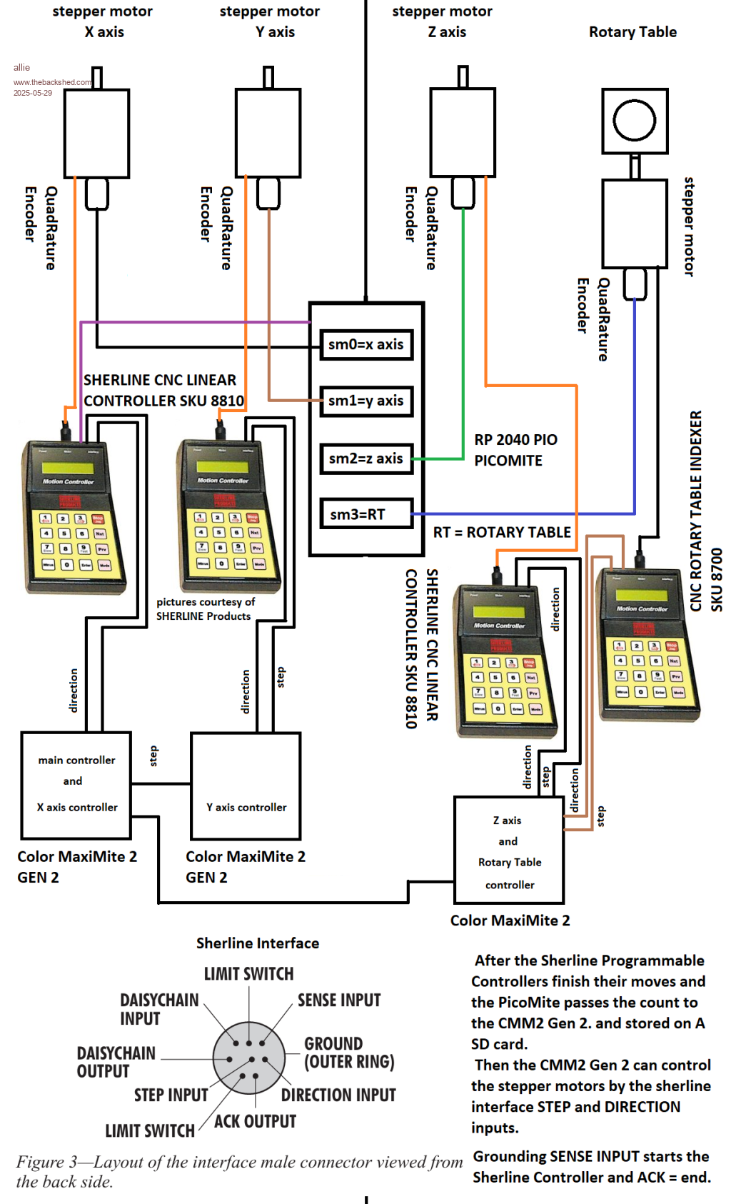 Maybe this worked. Allie |
||||
| allie Regular Member Joined: 06/10/2018 Location: CanadaPosts: 88 |
It worked but it to big may be I should use jpg format. Thanks TassyJim for the input. Allie |
||||
| allie Regular Member Joined: 06/10/2018 Location: CanadaPosts: 88 |
I'll upload the diagram in jpg.  Here It is in jpg Allie |
||||
| allie Regular Member Joined: 06/10/2018 Location: CanadaPosts: 88 |
OOPS its still to big. Sorry about that. At least you can see what I'm trying to do. I'll put it back in paint and down size it to 25%. I'll use Preview Post next time first. Regards Allie |
||||
| PhenixRising Guru Joined: 07/11/2023 Location: United KingdomPosts: 2005 |
How about a quick rundown of what the goal is...maybe I missed it. The way I interpret it is that a single PicoMite would suffice. |
||||
| allie Regular Member Joined: 06/10/2018 Location: CanadaPosts: 88 |
Try this  It a bit blurry but here it is. Allie |
||||
| allie Regular Member Joined: 06/10/2018 Location: CanadaPosts: 88 |
Here is a picture of the SHERLINE DRO encoders. I'm going to hook them to the PicoMite. 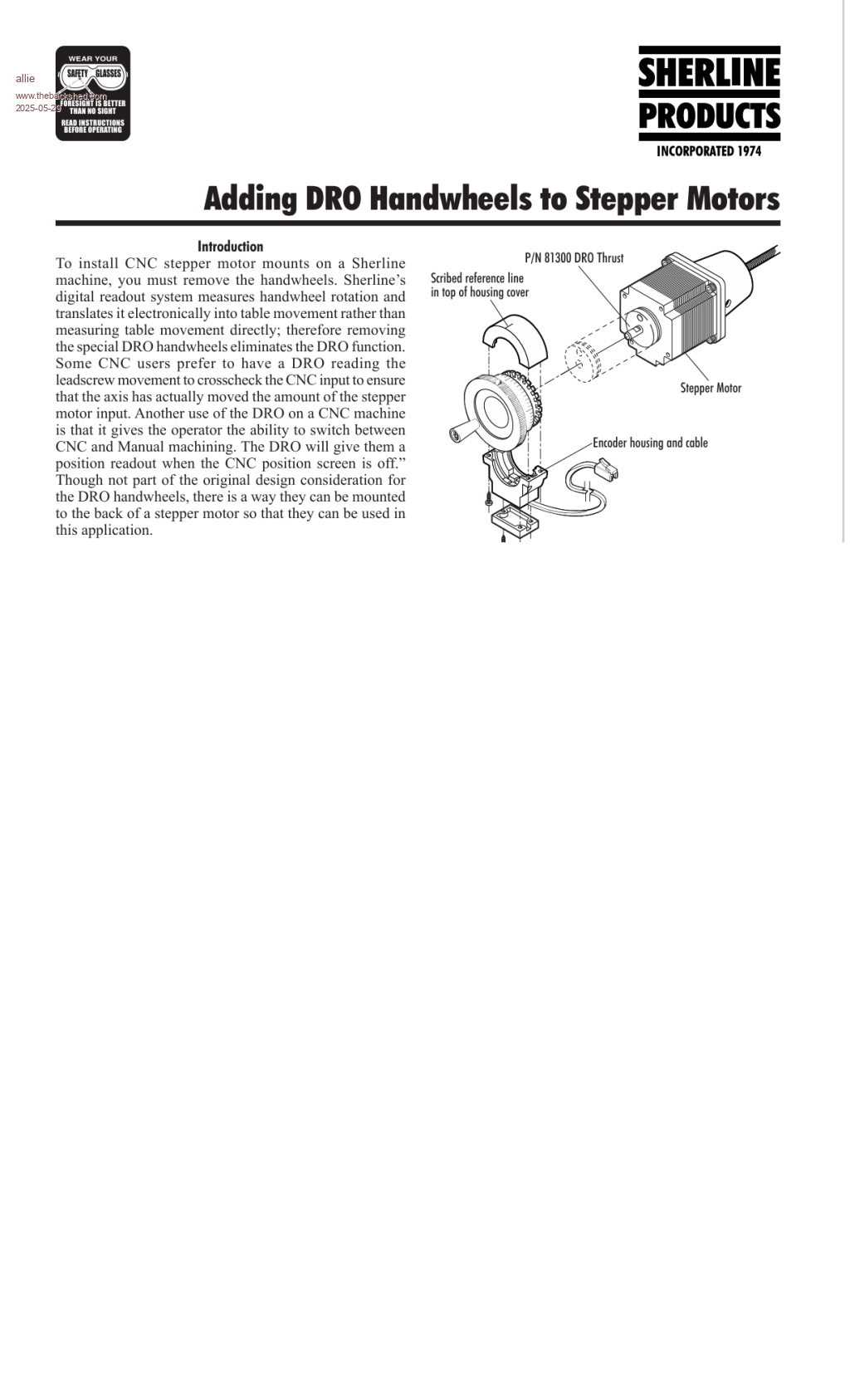 Regards allie. |
||||
| PhenixRising Guru Joined: 07/11/2023 Location: United KingdomPosts: 2005 |
Three linear axes and a rotary. This means coordination and interpolation across three CMM2s. Why not use FluidNC or such like? Edited 2025-05-29 16:53 by PhenixRising |
||||
| dddns Guru Joined: 20/09/2024 Location: GermanyPosts: 875 |
Agree. GRBL 4 axis to step/dir of your controllers and CMM2 as frontend. It took such as GRBL 15 years to reach that maturity. step/dir with this is an alternative perhaps. Edited 2025-05-29 17:40 by dddns |
||||
| Mixtel90 Guru Joined: 05/10/2019 Location: United KingdomPosts: 8965 |
Am I being a bit dense? This looks complicated but there may be good reasons for it. Surely, a PicoMite for each channel and one CMM2 linked to all four. The PicoMites can be identital. This is what they were designed for - embedded control. Each has a stepper motor driver and reads the quad encoder - and possibly the limit switches but that's only a state reading, not a control function. It can almost certainly do micro-stepping as that's a software function, I understand, not something special about the hardware. The CMM2 just sends commands to each channel telling it what to do and it does it. A return data channel tells it what is happening. The four comms channels would depend on distance and what the CMM2 can do. In actual fact it may have to be multidrop, such as RS-485 as the CMM2 hasn't got four comms ports of the same type. You then have two programs to write. One for the PicoMites and a Library for the CMM2 The PicoMites contain a comms section, encoder reader and stepper driver. Possibly switch inputs to indicate that a limit switch has operated and, if the driver supports it, motor overcurrent. The CMM2 sends commands to control the PicoMites. Your main program then simply uses the Library as a "language". Manual control of each channel would be via the CMM2 in "Manual" mode. Depending on complexity it might even be possible to use a PicoMite with touch screen instead of the CMM2, but that may be pushing things too far. Mick Zilog Inside! nascom.info for Nascom & Gemini Preliminary MMBasic docs & my PCB designs |
||||
| dddns Guru Joined: 20/09/2024 Location: GermanyPosts: 875 |
Made for this? |
||||
| PhenixRising Guru Joined: 07/11/2023 Location: United KingdomPosts: 2005 |
One Picomite should be able to handle the whole thing, the only unknown is generating the pulses. Interpolation, etc., is certainly do-able (I do it) with a DCS (distributed control system) but it's easier to handle on a single device. I don't understand exactly the end-goal....capture and replicate? Not as easy as it sounds. |
||||
| Mixtel90 Guru Joined: 05/10/2019 Location: United KingdomPosts: 8965 |
That's the point. The CMM2 sends "device j go to point n at speed q" and then goes to do something else. It doesn't need to generate pulses - it has no part in that, it's a PicoMite job. One PicoMite only produces pulses for one motor and only needs to read one encoder. Picos are cheap - dirt cheap compared to decent steppers, why lever everything into one? Let a single Pico be an intelligent stepper, in effect, handling its own control loop. Each channel's speed is limited by what the Pico can handle. Probably fast. The overall speed is limited by how fast the comms loop runs. 4-wire RS-485 would give a return channel for ACK and status without cluttering up the control channel. The CMM2 could even run time-sliced like a PLC. Read all the status bytes. Do the instructions into a buffer. Write all the control bytes. Loop back and wait for the next scan time. It would probably be slower though. This is expandable to as many Picos the CMM2 can talk to! . Edited 2025-05-29 19:31 by Mixtel90 Mick Zilog Inside! nascom.info for Nascom & Gemini Preliminary MMBasic docs & my PCB designs |
||||
| PhenixRising Guru Joined: 07/11/2023 Location: United KingdomPosts: 2005 |
Wish I had a stepper. Curious about the BITSTREAM thing. |
||||
| Mixtel90 Guru Joined: 05/10/2019 Location: United KingdomPosts: 8965 |
Simulate one using a second Pico and some LEDs. :) Mick Zilog Inside! nascom.info for Nascom & Gemini Preliminary MMBasic docs & my PCB designs |
||||
| PhenixRising Guru Joined: 07/11/2023 Location: United KingdomPosts: 2005 |
In my case, we don't have enough array space so a given move might need lots of BITSTREAM repeats. In the case of a real motor, I expect the motion to be seamless but it's always nice to verify. |
||||
| The Back Shed's forum code is written, and hosted, in Australia. | © JAQ Software 2026 |
