
|
|
Forum Index : Microcontroller and PC projects : The 2350B 64 pin board for my CNC
| Author | Message | ||||
| dddns Guru Joined: 20/09/2024 Location: GermanyPosts: 875 |
It might be a newer IPS panel, so I would try ILI9488W in first instance @Bryan: A picture of the display could help Edited 2025-07-13 22:59 by dddns |
||||
Bryan1 Guru Joined: 22/02/2006 Location: AustraliaPosts: 2161 |
Morning Guy's well over a caffine decided to try a few options so I tried different drivers and to my surprise the backlight worked with EVERY driver but the gui test lcdpanel failed on every one Here is a pic of the back of the lcd 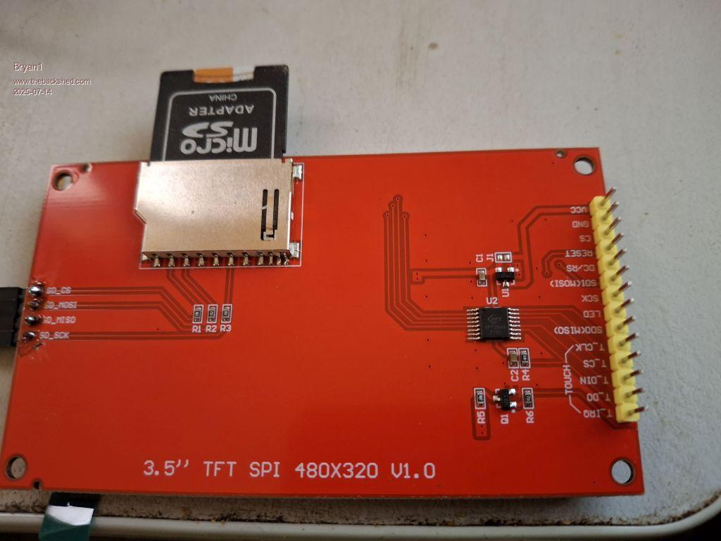 So my next job with this is to rip out all the wiring and start again just to see if that is the problem. |
||||
| phil99 Guru Joined: 11/02/2018 Location: AustraliaPosts: 3321 |
Ok that looks like a standard ILI9488 and has U1 fitted so Vcc should be 5V. If you can wire it up like this, which I have working, hopefully there will be a different outcome. Only System SPI & LCDPANEL drivers installed (no touch or SD) Panel Pico VCC VSYS (5V) GND GND CS GP13 RESET GP14 DC/RS GP15 SDI(MOSI) GP19 SCK GP18 LED GP7 In your first test the SD card also didn't work suggesting the SPI wiring may be the culprit, provided the SD card was no more than 32GB as that is all the LittleFS in the Pico can handle. If the panel still doesn't work the SPI bus can be checked with just the SD card. Remove the LCDPANEL and driver and add the SDCARD driver Edited 2025-07-14 10:22 by phil99 |
||||
| Bryan1 Guru Joined: 22/02/2006 Location: AustraliaPosts: 2161 |
Well rewired it all up did a clear flash and put 6.03 back on and just did the lcdpanel option and noticed it didn't light up like before so did a gui test lcdpanel and got the bubbles  Went and did the gui calibrate and got thru it first time. Went and did the gui calibrate and got thru it first time.PicoMite MMBasic RP2040 Edition V6.00.03 OPTION SYSTEM SPI GP18,GP19,GP16 OPTION COLOURCODE ON OPTION CPUSPEED (KHz) 200000 OPTION LCDPANEL ILI9488, RLANDSCAPE,GP15,GP14,GP13,GP7 OPTION TOUCH GP12,GP11 GUI CALIBRATE 0, 240, 204, 1251, 858 OPTION SDCARD GP22 So got the lcd and touch working and I replaced the 32gig sdcard with a 2 gig but still no sign of the sdcard working PicoMite MMBasic RP2040 Edition V6.00.03 OPTION SYSTEM SPI GP18,GP19,GP16 OPTION COLOURCODE ON OPTION CPUSPEED (KHz) 200000 OPTION LCDPANEL ILI9488, RLANDSCAPE,GP15,GP14,GP13,GP7 OPTION TOUCH GP12,GP11 GUI CALIBRATE 0, 240, 204, 1251, 858 OPTION SDCARD GP22 > files A:/ <DIR> . <DIR> .. 00:00 01-01-2024 4 bootcount 2 directories, 1 file, 692224 bytes free > So a bit more sleuthing to to work this sdcard one out. |
||||
| phil99 Guru Joined: 11/02/2018 Location: AustraliaPosts: 3321 |
Good to hear the LCD is working! The SD card is drive B: Type B:<enter> at the prompt to change drives then "files" A 32GB card should be ok but that is the maximum. Edited 2025-07-14 13:12 by phil99 |
||||
| Bryan1 Guru Joined: 22/02/2006 Location: AustraliaPosts: 2161 |
[CODE> B: > files B:/ <DIR> dtxhelp 11:48 18-02-2012 589 dates.txt 16:10 05-07-2013 108160 DTXHELP.TXT 10:11 19-08-2018 2039 EDITOR.TXT 10:11 19-08-2018 799 FUN1WIRE.BAS 10:11 19-08-2018 4798 ONEWIRE.BAS 18:13 18-08-2018 23970870 ruff.bmp 00:00 01-01-2000 640 TEMP.BAS 1 directory, 7 files >] Thanks Phil now time for lunch then spend some time reading the manual to get the gui setupAs one can see from the dates this is how long I have been away from this Edited 2025-07-14 13:17 by Bryan1 |
||||
| Bryan1 Guru Joined: 22/02/2006 Location: AustraliaPosts: 2161 |
Well just read right thru the Advanced Graphics PDF and at no point did I see any reference to in/out pins so are any examples around where it does show as it would be great in me learning. Now with this 2040 and the LCD my goal is to use for reading the cnc input/output like the limit switch's and temp probes I'm going to in each heatsink of the DM556's so I can check if they are going to heat up too much. Also it would be good on gui page 2 to have a toggle setup for jogging each axis. I do need to get on and purchase a heap of stuff for the big pico so for now I'm going to sort out the 2040 where I can. Just got a bit more wiring to do on the cnc then I use the 2040 to run that test code so I can get each step calibrated. |
||||
| phil99 Guru Joined: 11/02/2018 Location: AustraliaPosts: 3321 |
What you want is in the main manual p45 "Using the I/O pins" As you have found the Advanced Graphics PDF covers displaying the data after you have got it, and user input via the touch screen. I usually start just using the console for showing data and user input. After getting and processing the data is all bug free it is time to add all the graphics etc. The main manual also has a chapter on Graphics Functions. Edited 2025-07-14 22:40 by phil99 |
||||
| Bryan1 Guru Joined: 22/02/2006 Location: AustraliaPosts: 2161 |
As I only have a small breadboard decided to do a bit of shopping on fleabay and got a big breadboard, 10 off 40 pin male single pin headers, 10 off female headers and found 20 off sharp PC817 opto's for $3. So this will get me going with the big pico and once I have everything working a pcb can be designed. Now with the PC817 what sized resistor is used on the input side? Looking at the datasheet didn't give any clues but this ol' grey mattered brain hasn't looked at a datasheet in years  |
||||
| PhenixRising Guru Joined: 07/11/2023 Location: United KingdomPosts: 2005 |
In my case, which is 24VDC, I currently have 2K2, 500mW (to be safe) spec'd but I might increase that resistance. These are only input signals from machine sensors. |
||||
| Bryan1 Guru Joined: 22/02/2006 Location: AustraliaPosts: 2161 |
I will be using the opto's for the step, direction and enable signals now as the pico only outputs 3V3 I will be using 5V on the opto output so suit the minimum spec's of the DM556. Still got a couple of weeks for everything to arrive so gotta get my thinking cap on so everything falls into place. I do need to make list of all the passives I will need and I'll do a trip down the hill to get all the parts. |
||||
| Mixtel90 Guru Joined: 05/10/2019 Location: United KingdomPosts: 8965 |
Depends on what voltage you want to use for the inputs. Opto-couplers are current driven, not voltage. I'd allow a couple of mA. As an example I'll work it out for 12V input. The forward voltage Vf is a maximum of 1.4V for the PC817 so, the voltage across the resistor will be 12 - 1.4 = 10.6V I'll allow 3mA for the forward current. The resistor will have a value of 10.6 / 0.003 = 3533Ω The closest standard value to this is 3.3K. Working back, this will give a current of 10.6 / 3300 = 0.0032A (3.2mA) The resistor will dissipate some heat. We can calculate this using P=I*I*R: P = 0.0032 * .0032 * 3300 = 0.034W which is no problem at all. As this is operating the PC817 towards the bottom end of its current range you can use the same resistor value up to about 32V DC input: Voltage drop = 32-1.4=30.6V Current = 30.6/3300=9.2mA Dissipated power = .0092*.0092*3300=0.279W So you'd get away with a 0.5W resistor If you drop the input voltage to 6V using the same resistor the current will halve to about 1.5mA (not accurate as Vf changes at low current). This might just be possible as the collector current that you are after is only low when you want inputs. Opto couplers have what's called a Current Transfer Ratio, which is the ratio of the collector current to the diode current - rather like the current gain. The minimum for this opto coupler is 50 at 5mA. The range of transfer ratio is shown on the device by a letter code. I'm guessing that these will be the minimum of 80-160%. So, as the maximum allowable collector current is 50mA for this device 1mA through the diode should be fine. Mick Zilog Inside! nascom.info for Nascom & Gemini Preliminary MMBasic docs & my PCB designs |
||||
| Bryan1 Guru Joined: 22/02/2006 Location: AustraliaPosts: 2161 |
Well guy's decided to go and have a look on fleabay and found an Aussie vendor so got a CNC breakout controller board on the way with a copy of Mach3. I did take a look and Mach3 will work on win10 and with my laptop having 32 gig of ram don't think i'll have any problems of it hanging like my old 32 bit computer did. Got plenty of stepper motors here so still got a heap of fun as I do have a heap of old stepper chips which can come out of the cobwebs and finally get put to use. |
||||
| dddns Guru Joined: 20/09/2024 Location: GermanyPosts: 875 |
Hello Bryan, I'm using GRBL and the puristic but fantastic GUI Candle2 This is very clear and I can concentrate not to jog into material nor crashing beyond boundaries. The jogging feature is well done and is good to control. It offers a nice visualization but no features to e.g. mill a pocket. I always feed it with exported gcode from freecad or kicad/pcb2gcode(GUI) or write it by hand. Fluid has a jogging feature and a Web GUI integrated. I think your controllers could be connected to GRBL or FluidNC Best wishes |
||||
| PhenixRising Guru Joined: 07/11/2023 Location: United KingdomPosts: 2005 |
I plan to grab a FluidNC at some point. Volhout gave us PIO pulse/direction counting. I would simply use the count as a position command to drive closed-loop servos. There are many who want to replace dead CNCs but need to retain the performance of their existing servo-drives. The same applies to the Industrial CNCs on AE. They have all the advanced features but they are unable to directly control servo-drives. They output step and direction and so it would require new drives (that accept step/dir), motors, cabling, etc. Some of them can output 500K steps/sec. Not a problem for the Pico's PIO.  |
||||
| Bryan1 Guru Joined: 22/02/2006 Location: AustraliaPosts: 2161 |
G'Day Guy's, Well here is the CNC controller breakout board and it should be here before the weekend So first job will be hooking this up and getting Mach3 to work with it, then getting the calibration right. Then I am thinking of setting up my 2040 with the ILI9488 as a visual and hooking up the limits to the board, then the connection can be made to the inputs on the breakout board. Fun times ahead and I am looking to finally getting this CNC going again after it being idle for well over a decade. |
||||
| Bryan1 Guru Joined: 22/02/2006 Location: AustraliaPosts: 2161 |
Just had a look at the tracking and the controller will be here today Anyway got onto Evans & Clarke and scored a HP mini with win10 enterprise and a 24" monitor to dedicate for the cnc. As the mini does have ethernet I can hook it up to the network in my shed so it has access to starlink for getting all the software I will need then it can just stay off line and do it's job. |
||||
| Bryan1 Guru Joined: 22/02/2006 Location: AustraliaPosts: 2161 |
Well got this new computer all setup and decided to go down to the shop to see if any parcels did arrive. To my surprise 4 of them did so now got the big breadboard, the male inline pins, the female inline sockets and best of all the CNC package.Read all the info and when I went to install Mach3 it crashed saying it is missing ddls etc so tethered my mobile and first thing downloaded firefox as that is my favorite browser and to be honest aint tried any others as firefox just works. So doing a windows update and I'll give it another go but it does look like a job for tomorrow. |
||||
| Volhout Guru Joined: 05/03/2018 Location: NetherlandsPosts: 5994 |
Hihi, they will send you Mach3 software on a cd. The HP mini dpes not have a cd drive. Volhout PicomiteVGA PETSCII ROBOTS |
||||
| Volhout Guru Joined: 05/03/2018 Location: NetherlandsPosts: 5994 |
Hihi, they will send you Mach3 software on a cd. The HP mini dpes not have a cd drive. Volhout PicomiteVGA PETSCII ROBOTS |
||||
| The Back Shed's forum code is written, and hosted, in Australia. | © JAQ Software 2026 |
