
|
|
Forum Index : Microcontroller and PC projects : Pico Radar
| Author | Message | ||||
| Pluto Guru Joined: 09/06/2017 Location: FinlandPosts: 411 |
Gerald many thanks for the clarification. Pluto |
||||
TassyJim Guru Joined: 07/08/2011 Location: AustraliaPosts: 6547 |
I have been testing the RD-03D. The basic commands are the same. I didn't have a display so this code is for a VT100 terminal. ' RD-03D radar module VT display OPTION EXPLICIT OPTION DEFAULT INTEGER OPTION BASE 0 DIM record$, rec$ DIM debug = 1 DIM cmdDelay = 50 DIM Xscale = 80 DIM Yscale = 160 DIM multi = 1 DIM x1,x2,x3,y1,y2,y3,v1,v2,v3,prec1,prec2,prec3 DIM dataAvailable DIM hdr$= hex2str$("AAFF0300") DIM foot$ = Hex2Str$("55CC") DIM cmdHdr$ = hex2str$("FDFCFBFA") DIM cmdFoot$ = hex2str$("04030201") DIM enableConf$ = hex2str$("FDFCFBFA0400FF00010004030201") DIM endConf$ = hex2str$("FDFCFBFA0200FE0004030201") DIM ackEnableConf$ = hex2str$("FDFCFBFA0800FF010100400004030201") DIM ackEndConf$ = hex2str$("FDFCFBFA0400FE01000004030201") DIM singleTarget$ = hex2str$("FDFCFBFA0200800004030201") DIM ackSingleTarget$ = hex2str$("FDFCFBFA04008001000004030201") DIM multiTarget$ = hex2str$("FDFCFBFA0200900004030201") DIM ackMultiTarget$ = hex2str$("FDFCFBFA04009001000004030201") SETPIN GP1, GP0, COM1 OPEN "com1: 256000" AS #3 PRINT CHR$(27)+"[2J"; IF multi THEN setmulti ELSE setsingle IF debug THEN PAUSE 4000 ENDIF CLOSE #3 SETPIN GP1, GP0, COM1 OPEN "com1: 256000, 1024,radar,10" AS #3 DO rec$ = INPUT$(255,#3) LOOP UNTIL LEN(rec$) = 0 PRINT CHR$(27)+"[2J";CHR$(27)+"[1;40H"; DO IF dataAvailable THEN processIt 'pause 10 IF INKEY$="c" THEN PRINT CHR$(27)+"[2J"; IF INKEY$="d" THEN debug = 1 - debug LOOP SUB radar LOCAL st,fin, lenr lenr = LEN(rec$) rec$ = rec$+INPUT$(255-lenr,#3) st = INSTR(rec$,hdr$) IF st THEN rec$= MID$(rec$,st) fin = INSTR(rec$, foot$) IF fin THEN record$ = LEFT$(rec$,fin+1) rec$ = "" 'mid$(rec$,fin+2) dataAvailable = 1 ENDIF ENDIF END SUB SUB processIt STATIC n dataAvailable = 0 x1 = Signed16(STR2BIN(UINT16,MID$(record$,5,2))) y1 = Signed16(STR2BIN(UINT16,MID$(record$,7,2))) v1 = Signed16(STR2BIN(UINT16,MID$(record$,9,2))) prec1 = STR2BIN(UINT16,MID$(record$,11,2)) ' if multi then x2 = Signed16(STR2BIN(UINT16,MID$(record$,13,2))) y2 = Signed16(STR2BIN(UINT16,MID$(record$,15,2))) v2 = Signed16(STR2BIN(UINT16,MID$(record$,17,2))) prec2 = STR2BIN(UINT16,MID$(record$,19,2)) x3 = Signed16(STR2BIN(UINT16,MID$(record$,21,2))) y3 = Signed16(STR2BIN(UINT16,MID$(record$,23,2))) v3 = Signed16(STR2BIN(UINT16,MID$(record$,25,2))) prec3 = STR2BIN(UINT16,MID$(record$,27,2)) ' endif INC n IF prec1 > 0 AND(n MOD 5) = 0 THEN plotit x1,y1,x2,y2 IF debug THEN PRINT CHR$(27)+"[36;2H";x1,y1,v1,prec1,x2,y2,v2,x3,y3,v3 ' for n = 1 to len(record$) ' print hex$(asc(mid$(record$,n,1)),2); ' next n ENDIF ENDIF END SUB FUNCTION Signed16(u AS INTEGER) AS INTEGER IF u AND &h8000 THEN Signed16 = u AND &h7FFF ELSE Signed16 = -u END FUNCTION FUNCTION Hex2Str$(txt$) LOCAL h FOR h = 1 TO LEN(txt$) STEP 2 Hex2Str$=Hex2Str$+CHR$(VAL("&h"+MID$(txt$,h,2))) NEXT h END FUNCTION SUB plotit ax1, ay1, ax2,ay2 LOCAL bx1,by1,bx2,by2 STATIC cx1=40,cy1,cx2=40,cy2 bx1 = ax1/Xscale +40 by1 = ay1/Yscale PRINT CHR$(27)+"["+STR$(cy1)+";"+STR$(cx1)+"H"+"1"; PRINT CHR$(27)+"["+STR$(by1)+";"+STR$(bx1)+"H"+"*"; cx1=bx1 cy1=by1 IF ax2 THEN bx2 = ax2/Xscale +40 by2 = ay2/Yscale PRINT CHR$(27)+"["+STR$(cy2)+";"+STR$(cx2)+"H"+"2"; PRINT CHR$(27)+"["+STR$(by2)+";"+STR$(bx2)+"H"+"*"; cx2=bx2 cy2=by2 ENDIF END SUB SUB setsingle LOCAL n LOCAL junk$ junk$ = INPUT$(255,#3) PRINT #3, enableconf$; PAUSE cmdDelay junk$ = INPUT$(255,#3) IF debug THEN IF junk$ = ackEnableConf$ THEN PRINT "ACK conf OK" ELSE FOR n = 1 TO LEN(junk$) PRINT HEX$(ASC(MID$(junk$,n,1)),2); NEXT n ENDIF ENDIF PRINT #3, singleTarget$; PAUSE cmdDelay junk$ = INPUT$(255,#3) IF debug THEN IF junk$ = ackSingleTarget$ THEN PRINT "ACK single OK" ELSE FOR n = 1 TO LEN(junk$) PRINT HEX$(ASC(MID$(junk$,n,1)),2); NEXT n ENDIF ENDIF PRINT #3, endconf$; PAUSE cmdDelay junk$ = INPUT$(255,#3) END SUB SUB setmulti LOCAL junk$, n junk$ = INPUT$(255,#3) PRINT #3, enableconf$; PAUSE cmdDelay junk$ = INPUT$(255,#3) PRINT #3, multiTarget$; PAUSE cmdDelay junk$ = INPUT$(255,#3) IF debug THEN IF junk$ = ackMultiTarget$ THEN PRINT "ACK multi OK" ELSE FOR n = 1 TO LEN(junk$) PRINT HEX$(ASC(MID$(junk$,n,1)),2); NEXT n ENDIF ENDIF PRINT #3, endconf$; PAUSE cmdDelay junk$ = INPUT$(255,#3) END SUB No comments in the code yet. Sorry. A sample readout after we wandered about the house this morning. It looks like a Poodle! 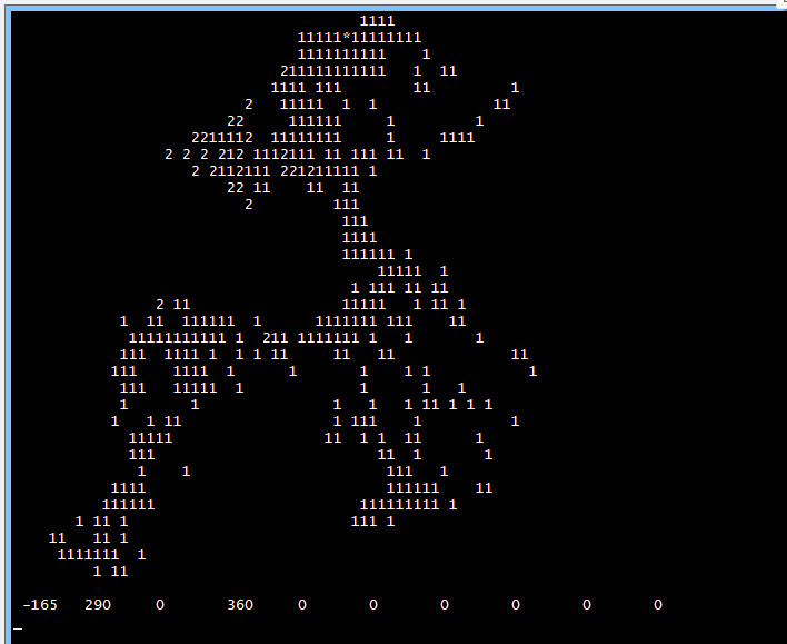 The radar goes through walls better that I had expected but I will set it up in a better location and use a Webmite + Telnet. Jim VK7JH MMedit |
||||
| v.lenzer Senior Member Joined: 04/05/2024 Location: GermanyPosts: 123 |
Hi Gerald! I've drawn a radar grid for it. Works perfectly. 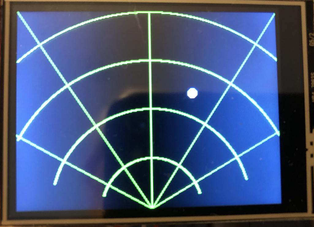 Best wishes! Joachim |
||||
| v.lenzer Senior Member Joined: 04/05/2024 Location: GermanyPosts: 123 |
Hi TassyJim! Your code also works perfectly with an LP2450. I just had to swap GP0 and GP1. Best wishes! Joachim |
||||
| Wolfgang Regular Member Joined: 03/11/2021 Location: GermanyPosts: 88 |
Very impressive, I'm impatiently awaiting my LD2450 Wolfgang |
||||
| ville56 Guru Joined: 08/06/2022 Location: AustriaPosts: 550 |
Now that the basic problems are solved, Andrew can start constructing his cat repellent device, but just for 3 cats at a time ... Or with 3 sensors and a software that negotiates area filtering between them, so up to 9 cats can be tracked ...  73 de OE1HGA, Gerald |
||||
| TassyJim Guru Joined: 07/08/2011 Location: AustraliaPosts: 6547 |
I can confirm that the radar will detect a small 5kG dog so cats should be doable. AS long as they keep moving. Jim VK7JH MMedit |
||||
palcal Guru Joined: 12/10/2011 Location: AustraliaPosts: 2039 |
@ v.lenzer, would you mind sharing your code. Thanks. "It is better to be ignorant and ask a stupid question than to be plain Stupid and not ask at all" |
||||
| v.lenzer Senior Member Joined: 04/05/2024 Location: GermanyPosts: 123 |
This is my first version of the radar program. I haven't changed much. After starting, it automatically switches to display mode (line 121). However, the menu remains on the console. The "single person mode" is also set (line 133). The pins for TXD and RXD are gp0 and gp1. The radar grid is drawn in sub_radr_net and called in line 290. The program is based on LD2450LD-V2.1.bas. In version 2.3, the radar dot wasn't stable enough for me when nothing was moving. I can't guarantee that everything is correct, but it works perfectly. The mobile app was also helpful. It allows you to check if the radar is reliably detecting and which mode is selected. I'm currently working on getting the settings menu onto the touchscreen. I think that will work. Radar_v.1.bas.zip Best wishes! Joachim |
||||
| palcal Guru Joined: 12/10/2011 Location: AustraliaPosts: 2039 |
Thanks for that. "It is better to be ignorant and ask a stupid question than to be plain Stupid and not ask at all" |
||||
| palcal Guru Joined: 12/10/2011 Location: AustraliaPosts: 2039 |
Got it working but the dot on the screen does not seem to follow a moving person as it should, in fact it does move much at all. I am using the RD-03 maybe that makes a difference. Range is less than 1 metre. I found an article on a local suppliers web site here in Aust. how it works and code in MicoPyhton. Here Thanks for the code Gerald and Joachim, great work. Edited 2025-12-08 09:58 by palcal "It is better to be ignorant and ask a stupid question than to be plain Stupid and not ask at all" |
||||
| ville56 Guru Joined: 08/06/2022 Location: AustriaPosts: 550 |
RD-03 is the same sensor. Have you checked Vcc/Gnd and rx/tx lines. If you connect the sensor to a serial-to-USB adapter and supply it with 5V you should see data comeing with 256000 baud. But this default can be changed permanently, so you better check. A scope or a logic analyzer may also help Gerald 73 de OE1HGA, Gerald |
||||
| palcal Guru Joined: 12/10/2011 Location: AustraliaPosts: 2039 |
It is working, the dot moves but not like it should, it just wanders slightly around the zero position on the display. Here are a couple of screen shots .png) .png) When sitting infront of it the dot hovers around the zero mark, when I move to a position about 3 metres away the dot moves down about 2 lines on the grid, ie about half way, but only down the left hand side. It keeps losing sync. I don't know what that means. . Edited 2025-12-08 16:05 by palcal "It is better to be ignorant and ask a stupid question than to be plain Stupid and not ask at all" |
||||
| phil99 Guru Joined: 11/02/2018 Location: AustraliaPosts: 3321 |
My guess is its Tx baud rate is different to your RX baud rate. With a MicroMite connected to TeraTerm at the wrong baud rate you can get random characters on the screen and it looks like your program is getting that. Use TeraTerm and experiment with different baud rates until the data looks sensible then adjust the program to use that baud rate. |
||||
| palcal Guru Joined: 12/10/2011 Location: AustraliaPosts: 2039 |
Thanks for that Phil, I'll try in the morning. "It is better to be ignorant and ask a stupid question than to be plain Stupid and not ask at all" |
||||
| ville56 Guru Joined: 08/06/2022 Location: AustriaPosts: 550 |
sync lost means that the expected header chars are not received and the app waits for them to come by again. Seems like there are characters lost from the serial line. The serial line itself seems to be setup properly and the senor deliveres data, otherwise you would not get sync lost/sync established messages. If the range-sensitivity is too low, you can use a different scaling factor for calibration. I've set it up for 6 meters for full display, but it seems that the distance readout from the sensor is not very accurate as I measured 3 meters in y-axis distance as being about 1/4 of the display distance only. Didn't dig deeper as I think this can be calibrated out. The lost chars may be because of too low cpu speed or too much time consumed for other code like display update. I've run that on a pico2 RP2450 with 300 Mhz and didn't lose chars except when switching from single to multi-target mode. Could be that the display thakes too much time for drawing the lines/ball. Had a SPI display with standard driver. so nothing really fast.... If I find some time theses days I can try to run that on a pico 1 with low cpu speed and see what the behavior is. Edit: scaling factors are calculated in lines 103/104, the divisor is the maximum length in mm. Gerald Edited 2025-12-08 18:53 by ville56 73 de OE1HGA, Gerald |
||||
| v.lenzer Senior Member Joined: 04/05/2024 Location: GermanyPosts: 123 |
I'm getting these error messages too. I think it's actually related to the image rendering. I didn't pay much attention to it because the display still worked. I'll try it at 300 MHz today. And please note: I was using Gerald's version 2.1. Best wishes! Joachim |
||||
| ville56 Guru Joined: 08/06/2022 Location: AustriaPosts: 550 |
try to comment out line 315 (radar_net) just to see if this cures the sync issue. If so, there is too much cputime spent in drawing the grid. Maybe you then could try to use layers, one for the grid and one for the ball(s). This also applies to V2.1. As I already wrote, V2.1 uses even more cpu, as all the definitions for the header/trailer and data items are dynamic and also trailers are checked. So, yes, it may be a bit overengineered for this purpose .... but Jims very slick approach could be a good basis for low cpu usage. 73 de OE1HGA, Gerald |
||||
| v.lenzer Senior Member Joined: 04/05/2024 Location: GermanyPosts: 123 |
The distance between arcs is approximately 2 meters with these settings: const v_fact = mm.vres/8000 const h_fact = mm.hres/6200 At least, that's what my tests showed. Attempts with GUI SETUP and GUI PAGE didn't yield good results. While it works, the lines are deleted from the radar point. Now I need to look into the LAYERS issue. Best wishes! Joachim |
||||
| ville56 Guru Joined: 08/06/2022 Location: AustriaPosts: 550 |
just measured the time used for "radar_grid" drawing the grid: pico 2, 100Mhz: 69 mSec pico 2, 250Mhz: 32 mSec so with a pico 2 there is still some headroom, even with 100 Mhz. Have no free Pico 1 at hand but I think it can become tight ... The interval of measurements taken by the sensor is 100 mSec, so if the processing time in total exceeds this 100mSec synch will be lost and must be regained with the following data packet(s). Drawing the grid and the ball should be redesigned ... layers, sprites, ... have not enough experiance with graphics but I'm sure there are experts in this forum. Gerald 73 de OE1HGA, Gerald |
||||
| The Back Shed's forum code is written, and hosted, in Australia. | © JAQ Software 2026 |
