
|
|
Forum Index : Microcontroller and PC projects : how do setup picomite hdmiusb ??
| Author | Message | ||||
| Martin H. Guru Joined: 04/06/2022 Location: GermanyPosts: 1485 |
That's sadly still not the USB HDMI version. 'no comment |
||||
| Mixtel90 Guru Joined: 05/10/2019 Location: United KingdomPosts: 8964 |
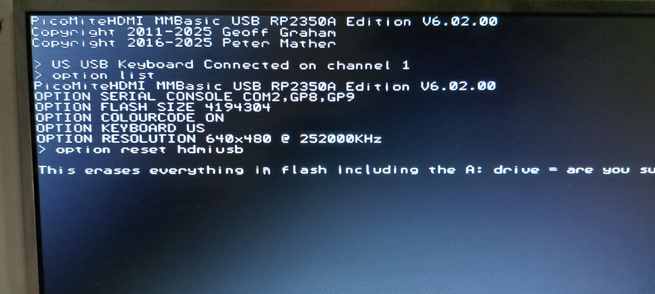
If you are able to connect to the Pico using the Prog microUSB socket (USB5) to install MMBasic then the connections to the Pico have to be ok. The Pico's USB socket is wired directly to that one via the pads underneath. The same connections feed the on-board USB hub vie CN4 links 1-2 and 3-4 so, if they are in place, then the USB hub must be connected. Install the PicoMiteHDMIUSB firmware via the microUSB socket. Unplug it - you don't want that lead now. Use a USB-C lead to connect USB2 to the PC and switch the Pico on. Start Tera Term In the Tera Term text window go to Setup/Serial Port and make sure the baud rate is set to 115200 baud. You should be able to find a serial COM port to connect to the Pico via the CH340C You should then be in console mode It might be a black screen so press Enter a couple of times Enter OPTION RESET HDMIUSB and everything should set up automatically You should be able to use a USB keyboard and HDMI monitor from this point . Edited 2026-03-01 20:51 by Mixtel90 Mick Zilog Inside! nascom.info for Nascom & Gemini Preliminary MMBasic docs & my PCB designs |
||||
| phil99 Guru Joined: 11/02/2018 Location: AustraliaPosts: 3321 |
I think putting solder in that hole is to provide heatsinking for that chip. The 3 pads he is reffering to have holes and can be seen in this pic. Two are at the top of the Pico footprint and one a little further down. https://www.thebackshed.com/forum/ViewTopic.php?TID=17301&P=4#228486 You need to solder through those holes to connect to the USB pads on the bottom of the Pico. Then you can load the HDMIUSB firmware again to see if it works properly. |
||||
| Mixtel90 Guru Joined: 05/10/2019 Location: United KingdomPosts: 8964 |
If *any* firmware can be loaded via the microUSB socket then the pads must be ok. They are simply point to point wired. Pins 1 and 3 of CN4 are on the same connections. You take the CN4 links off while programming anf put them back to connect the USB hub to the Pico. That microUSB isn't used for anything other than installing MMBasic. Mick Zilog Inside! nascom.info for Nascom & Gemini Preliminary MMBasic docs & my PCB designs |
||||
| tenij000 Senior Member Joined: 30/05/2025 Location: NetherlandsPosts: 107 |
 now here also 1 red light is on r59 active |
||||
disco4now Guru Joined: 18/12/2014 Location: AustraliaPosts: 1133 |
So what happened next? F4 H7FotSF4xGT |
||||
| tenij000 Senior Member Joined: 30/05/2025 Location: NetherlandsPosts: 107 |
it works now  problem was the led bihind the battery holder was rong way around problem was the led bihind the battery holder was rong way around |
||||
| disco4now Guru Joined: 18/12/2014 Location: AustraliaPosts: 1133 |
Are all the boards the same, or just the first unlucky one? F4 H7FotSF4xGT |
||||
| Mixtel90 Guru Joined: 05/10/2019 Location: United KingdomPosts: 8964 |
That's an interesting fault. /PWREN was unable to turn the power on to the USB sockets. Well spotted. :) Mick Zilog Inside! nascom.info for Nascom & Gemini Preliminary MMBasic docs & my PCB designs |
||||
| The Back Shed's forum code is written, and hosted, in Australia. | © JAQ Software 2026 |
