Notice. New forum software under development. It's going to miss a few functions and look a bit ugly for a while, but I'm working on it full time now as the old forum was too unstable. Couple days, all good. If you notice any issues, please contact me.
javavi Guru Joined: 01/10/2023 Location: UkrainePosts: 615
Posted: 09:26pm 14 Aug 2026
Copy link to clipboard
Print this post
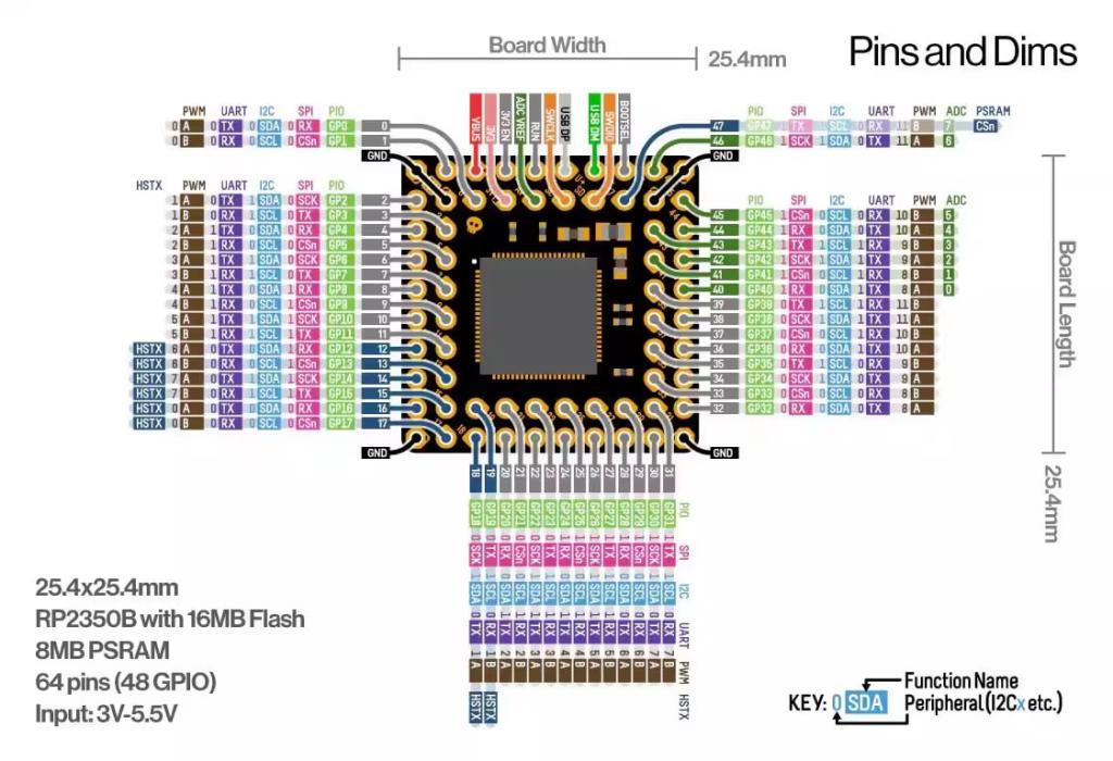
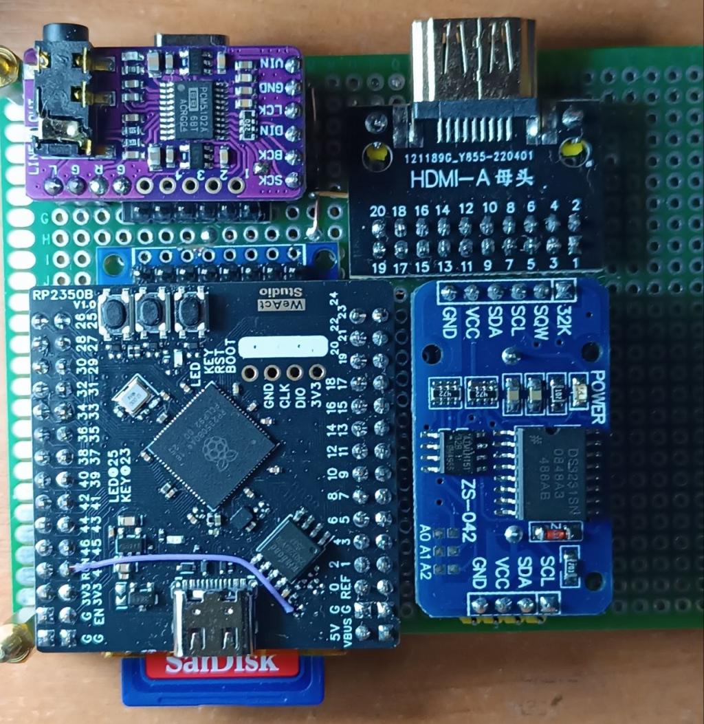
@lizby Salute my friend! I just started assembling this PC3 from readily available components. I've only just distributed power to the modules, and now they're glowing happily with their LEDs. The simplest and cheapest USB hub with a Type-C connector for direct connection to the controller port. They may look the same, but inside there will be different chips that may not work with the RP2350. The main thing is that the module can output power like a USB OTG. https://www.aliexpress.com/item/1005005859606670.html I ordered all modules and devices from AliExpress. WeAct RP2350B Raspberry Pi RP2350B (soldered the ESP-PSRAM64H chip to the bottom and modified the wire to CS this chip from the GP47 port.)
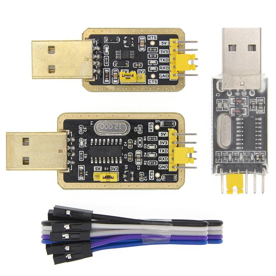
There is also an interesting ready-made processor module with a pre-installed PSRAM Raspberry Pi RP2350 Core2350B Core Board PSRAM I think you can use any HDMI module; many already have the necessary resistors soldered on and it will be easy enough to connect them with wires. I don't really like these small micro SD cards, so I used a module for a standard SD memory card. You also don't even have to install a USB-TTL serial adapter on the board, but use any external one similar to this one Overall, there's a lot of room for improvisation with these modules, good luck! Edited 2026-08-15 08:05 by javavi
lizby Guru Joined: 17/05/2016 Location: United StatesPosts: 3884
javavi Guru Joined: 01/10/2023 Location: UkrainePosts: 615
Posted: 07:36am 15 Aug 2026
Copy link to clipboard
Print this post
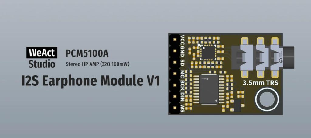
I use module PCM5102 DAC Decoder GY-PCM5102 I2S Player, the link to it is on the first page of this topic. https://www.thebackshed.com/forum/ViewTopic.php?FID=16&TID=18966#256839 An important note: you need to correctly install the jumpers, which may or may not be installed by the manufacturer, and also correctly supply signals, powering the module from 5V. I also have another interesting WeAct I2S Earphone Module PCM5100A sound module with a headphone amplifier HP AMP 32Ω 160mW. WeAct I2S Earphone Module PCM5100A Stereo HP AMP
Mixtel90 Guru Joined: 05/10/2019 Location: United KingdomPosts: 9174
Posted: 08:55am 15 Aug 2026
Copy link to clipboard
Print this post
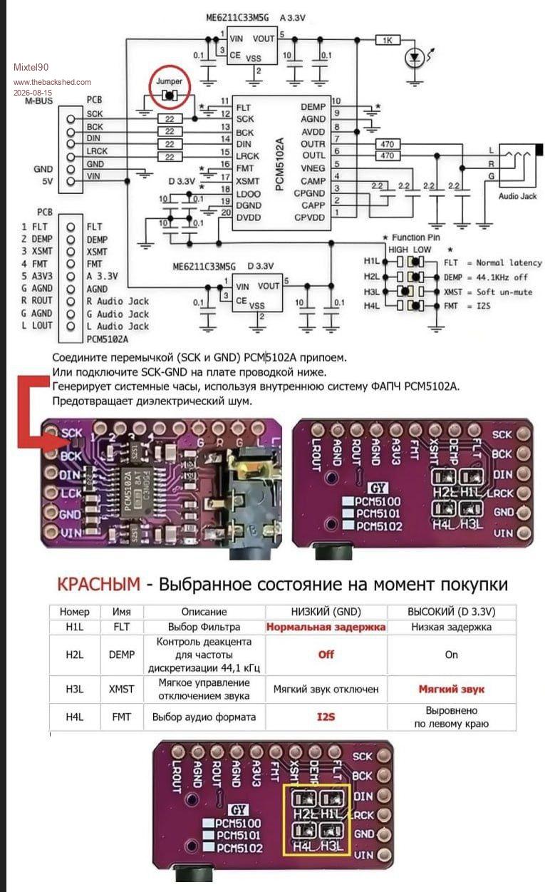
This may be of interest. Note the separate regulators for digital and audio supplies to the chip. Unfortunately I can't read any of the text. :)
javavi Guru Joined: 01/10/2023 Location: UkrainePosts: 615
Posted: 11:32am 15 Aug 2026
Copy link to clipboard
Print this post
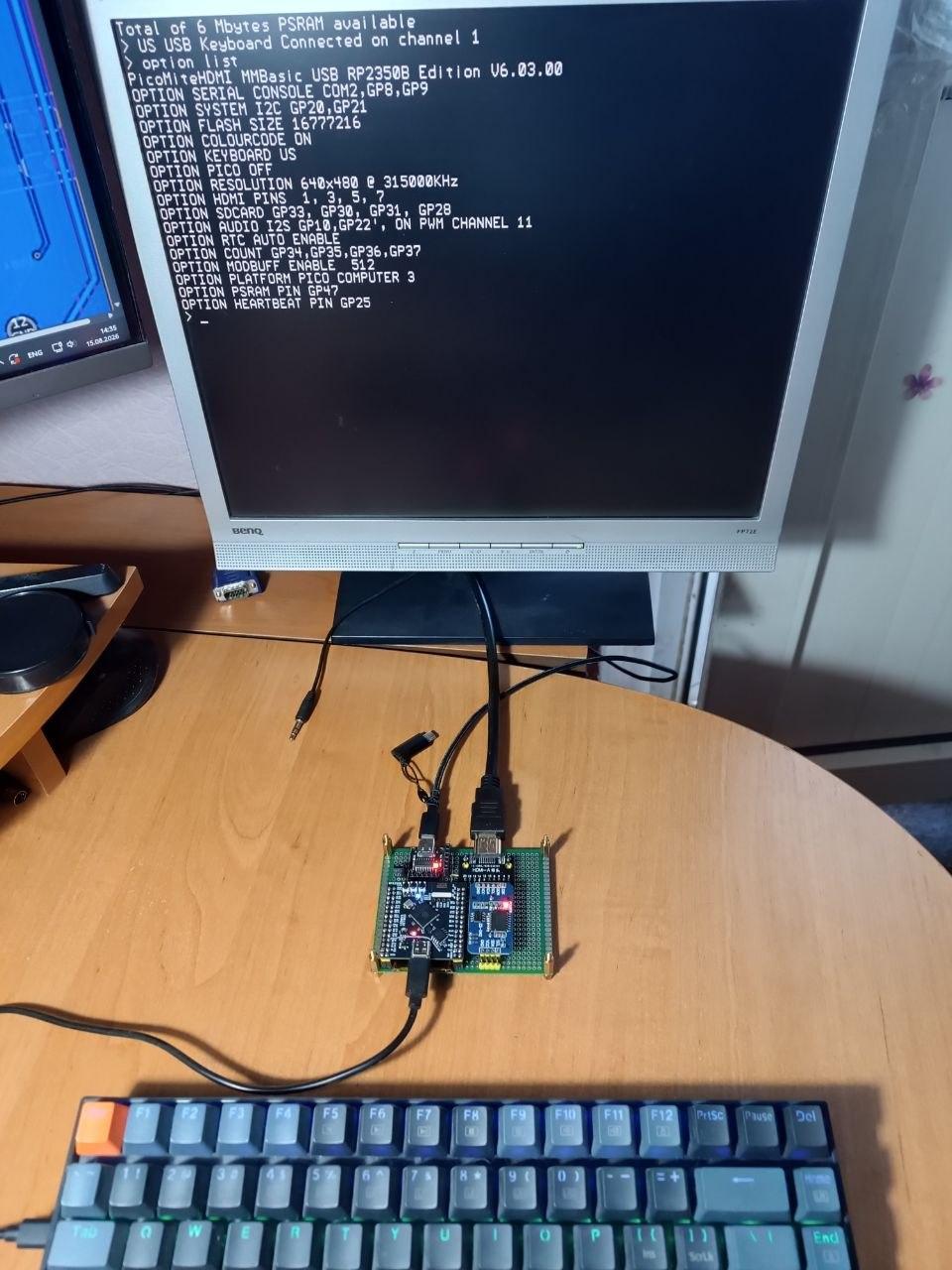
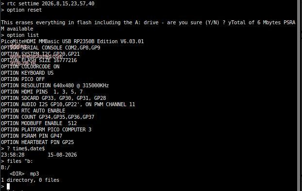
Hi Mick, Today I had some free time and electricity, so I pulled myself together and soldered a few wires onto my breadboard, and it (the PC3) worked right away.
Now I have a working HDMI video output, a serial console with a PC, PSRAM, an RTC clock, and a directly connected USB keyboard. I just need to finish the SD card and sound, and then I'll be ready to go. P.S. I also soldered three more wires to the PCM5102 DAC I2S module and voila, the sound started playing. Edited 2026-08-15 22:12 by javavi
Martin H. Guru Joined: 04/06/2022 Location: GermanyPosts: 1563
Posted: 12:15pm 15 Aug 2026
Copy link to clipboard
Print this post
Gemeni writes the following on this matter:
**Main Text (under the schematic):**
* **Соедините перемычкой (SCK и GND) PCM5102A припоем.** → Connect the PCM5102A jumper (SCK and GND) with solder. * **Или подключите SCK-GND на плате проводкой ниже.** → Or connect SCK-GND on the board using the wiring below. * **Генерирует системные часы, используя внутреннюю систему ФАПЧ PCM5102A.** → Generates the system clock using the internal PLL of the PCM5102A. * **Предотвращает диэлектрический шум.** → Prevents dielectric noise.
---
**Section Header (above table):**
* **КРАСНЫМ - Выбранное состояние на момент покупки** → **IN RED - Default factory state / State as purchased**
dddns Guru Joined: 20/09/2024 Location: GermanyPosts: 916
Posted: 11:23pm 15 Aug 2026
Copy link to clipboard
Print this post
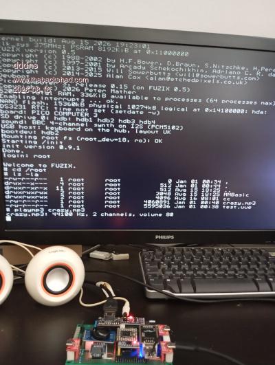
I also have my setup running in full on PicoMiteHDMIUSB. No problems with any components, and it goes straight into auto-configuration after flashing. The PCM5102 is great and delivers crystal-clear sound. Everything runs as smoothly as I’m used to, as well with Option resolution 640,378000
What I haven’t managed to do so far is get any sign of life from Fuzix. I’ve done everything as described, but it won’t boot, and there’s no display or console output. I’ve written the SD card using `dd` and a dedicated imaging tool. I can see the partitions under Linux with `fdisk`, but when I try to mount one, I get an error (bad superblock, etc.) Even when I mount the image as a loop device, I can’t read it. I’m not familiar with the boot behavior. At what point should output appear, and where? After flashing the Pico, or only once the SD card has been written correctly and is readable? I’m using a standard 32GB Class 10 SD card. Does anyone have any ideas on how I can move forward?
Edited 2026-08-16 09:26 by dddns
javavi Guru Joined: 01/10/2023 Location: UkrainePosts: 615
Posted: 07:56am 16 Aug 2026
Copy link to clipboard
Print this post
@dddns, I confirm, I have the same problem with this conFuzix I tried several different firmware versions (from V0.1) on my "devboard" today, but there is no HDMI video or console output. I also tried writing disk images to different SD cards several times. It seems to me that there is some kind of hidden magic here, or some kind of Easter egg from Peter. My guesses: 1. It's possible that the firmware doesn't start due to overclocking the processor frequency, and the firmware itself doesn't provide for increasing the core voltage, since the PC3 board has an external 1.3V core power supply. 2. Perhaps the firmware checks the equipment composition for the original PC3 board. , etc... We should probably ask Peter about this in the Fusix firmware thread. Please try asking him, as I'm probably driving him crazy with my stupid questions.
dddns Guru Joined: 20/09/2024 Location: GermanyPosts: 916
Posted: 08:18am 16 Aug 2026
Copy link to clipboard
Print this post
Hello Javavi,
Thanks for your reply; it helps that you tried different SD cards. I think I read that only a PGA and an SD card are needed to test Fuzix. I could be wrong, though, it might have been about MicroPython, which I also installed as a test and found that all the components responded immediately. The PGA I'm using is an old A2 stepping, what is yours?
Peter will surely read this at some point; if he wants to reply, he’ll do so.
It would be a shame if this didn’t work. I already have a perfect HDMI setup with the same functionality for PicoMite.
Translated with DeepL.com (free version)
dddns Guru Joined: 20/09/2024 Location: GermanyPosts: 916
Posted: 08:46am 16 Aug 2026
Copy link to clipboard
Print this post
Thanks for your post, that saved time! First I didn't have sound and then I soldered the bridges like you showed and that works. BTW, the PicoMite Manual shows exactly my module but does not mention, how to set the bridges.
javavi Guru Joined: 01/10/2023 Location: UkrainePosts: 615
Posted: 08:51am 16 Aug 2026
Copy link to clipboard
Print this post
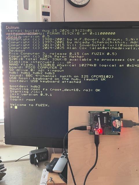
I have a WeArt RP2350B module with a chip RP2350B0A4, see my photos. By the way, some modules on the breadboard are located under other modules; this two-tier architecture greatly saves space on the device's breadboard. Edited 2026-08-16 18:57 by javavi
dddns Guru Joined: 20/09/2024 Location: GermanyPosts: 916
Posted: 09:03am 16 Aug 2026
Copy link to clipboard
Print this post
Good to hear that yours is A4 so there is hope for me as well :))
I wanted a compact build on a real single layer PCB layout. As small as possible is nice, but can it be routed? My HDMI setup for PicoMite with 2350B and all pins to headers is 74x58x25mm
Edit: No question, you setup looks brilliant! Edited 2026-08-16 19:04 by dddns
javavi Guru Joined: 01/10/2023 Location: UkrainePosts: 615
Posted: 09:30am 16 Aug 2026
Copy link to clipboard
Print this post
@dddns Fusix is working! Peter just rolled out a new Fusix firmware update, Version 0.15. As we correctly suspected, the problem was with the core power supply. The new version includes a software setting for the overclocked core controller voltage. Now we need to monitor stability; there might be reboots due to overheating; cooling might help.
Mixtel90 Guru Joined: 05/10/2019 Location: United KingdomPosts: 9174
Posted: 09:47am 16 Aug 2026
Copy link to clipboard
Print this post
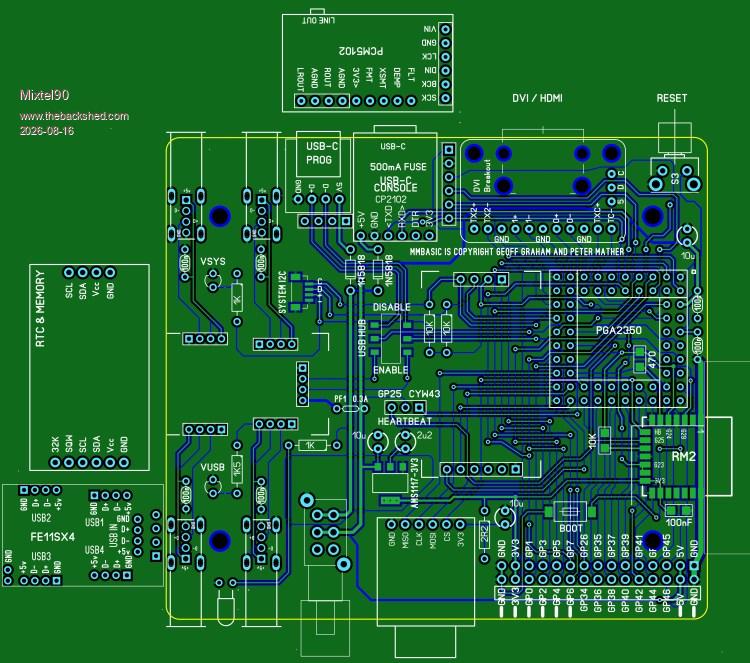
After seeing those designs I couldn't resist. I'm flippiin' awkward though, and I wanted it to fit into a case and fit onto a 100mm square board at most. :) I dug out a previous design for GAP3 and started hacking it about...
This design passes the "point to point" test and, apart from tiny text, the DRC in SL6. It more or less follows the same schematic that Peter originally posted for the PC3 and fits into the same case, although it uses modules and the layout is totally different of course. It may or may not fit into someone else's 3D printed case as the RM2 antenna projects from the PCB, but that's not my problem. :)
This is, of course, still a provisional design. There may be tweaking to do and nothing has been built, although it might be eventually as I have quite a few of the bits.
I could probably change the display so that it uses the plug-in modules that I'm using for Elemento, so it would be easy to have VGA, HDMI or, possibly, LCD displays but it would mess up the auto-recognition for the PC3 and the user would have to edit the display OPTION. Probably not worth it.Mick
dddns Guru Joined: 20/09/2024 Location: GermanyPosts: 916
Posted: 12:54pm 16 Aug 2026
Copy link to clipboard
Print this post
javavi Guru Joined: 01/10/2023 Location: UkrainePosts: 615
Posted: 02:48pm 16 Aug 2026
Copy link to clipboard
Print this post
You're doing great, Mick. I think these boards for building PICO COMPUTER 3 from ready-made modules will be in demand. When and where can I see your board design? Edited 2026-08-17 01:02 by javavi

 Notice. New forum software under development. It's going to miss a few functions and look a bit ugly for a while, but I'm working on it full time now as the old forum was too unstable. Couple days, all good. If you notice any issues, please contact me.


 Print this post