
|
|
Forum Index : Windmills : The MPPT Project.
| Author | Message | ||||
| RossW Guru Joined: 25/02/2006 Location: AustraliaPosts: 495 |
There is one more option, which adds some complexity, but which caters for most (or all) of your concerns. It's used widely in industry, but makes its way into all manner of things. It's called a "PID" controller. Basically, your input variable(s) are sensed, the output variable(s) controlled, and the "magic bit in the middle" is the PID controller. PID litterally standing for "Proportional, Integral and Derivative". Lets take a simple one-in-one-out PID controller. The current output state is compared to the desired value, and an error value determined. The control output is then adjusted by the sum of three calculations: Proportional (which is just the error value times the proportional gain and controls the transient response). Integral (which integrates the error over time, and controls the steady state output) Derivative (the rate-of-change of error output, and controls the stability) PID loops can be tricky to tune well, but do work very well and are well understood. |
||||
| Warpspeed Guru Joined: 09/08/2007 Location: AustraliaPosts: 4406 |
Yes You are quite right Ross, but the problem is that with a grossly non linear system the optimal proportional gain and the optimal integral time settings can be very different at different operating points. In such a situation a PID often has to be set with a very low gain, and very long integral time to ensure stability. That often produces very poor and very sluggish control characteristics. The performance can be so disappointing that the PID control method is just impractical in some situations. Cheers, �Tony. |
||||
Gill Senior Member Joined: 11/11/2006 Location: AustraliaPosts: 669 |
Just a minor point regarding feed forward from an anemometer. Unfortunately there is a lag time between increased wind speed and windmill response. This is not so much an issue in times of steady consistent wind, but in gusty conditions the peak wind power is never reflected in output power. Comment from a Fieldlines Forum contributor: 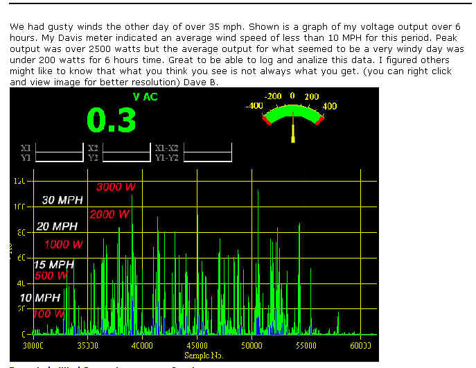
For this reason anemometer sample rates are made the same as windmill response times when used for power calculations. Of course response times vary between different mills for a number of reasons. In general smaller diameter props respond faster to gusts than larger ones. Perhaps in considering response times the feed forward signal could eliminate this variable by coming from prop RPM instead of anemometer RPM? was working fine... til the smoke got out. Cheers Gill _Cairns, FNQ |
||||
| Warpspeed Guru Joined: 09/08/2007 Location: AustraliaPosts: 4406 |
Quite right, rotor inertia will cause a lag in response for the larger machine, which is one issue that always greatly complicates a feedback system. Any feedback always needs to be applied slowly enough to prevent instability. With a PID controller, it is lags in the system that require the I (integral) term to be made adjustable over a wide range. But a feedforward system is quite different, because it can never become unstable. A difference in feedforward response speed will certainly cause some undesirable output fluctuations by correcting too early, but it is possible to add a phase correction lag to the output voltage from the anemometer to duplicate the inertia of the main mill. In effect the fast responding anemometer output, predicts what the main machine will eventually produce. The tuning of the feedforward voltage need not only be in amplitude, but also response time. Simple integration with an adjustable resistor capacitor time constant of the anemometer voltage could be made to duplicate inertia of the main mill fairly closely. Just logging wind speed and battery charging current should show if the MPPT is responding too quickly or too slowly to track properly. The problem with using prop rpm is that once it has been measured, and the feedforward voltage adjusts the PWM, the mechanical load on the prop will change. That alters the prop rpm, which further changes the PWM. The system will always be chasing it's tail. It may not work properly, or it may even become unstable or even run away under certain conditions. Much better to just measure wind speed directly and completely eliminate any possible feedback effect. Cheers, �Tony. |
||||
| GWatPE Senior Member Joined: 01/09/2006 Location: AustraliaPosts: 2127 |
A few comments. I have used PID systems myself. Air conditioner control. good use here, long system responce time constants. Heater element control. This was much faster response, 800 C and arount 200W heater. Even with auto tuning PID, settings for propotional Band, Derivative action time and integral action time still caused oscillations. These PID systems were designed for control of Process systems with long system time constants. Analogue computers provide the best control here. digital is catching up, but processing power would use most of mill output. The graph I posted shows that complete wind gust transients can occur within a 20 second period, from close to 0 power output, to max and down again. Mini gusts can be less than 1 second duration. The response time of the control has to be 100 times faster than the minimum system response time constant to prevent oscillations. It would be possible to use a cup anemometer to measure wind speed and then use a direct control system to control the modulator. The actual power of the mill at all windspeeds expected has to be known. There should be compensation for air temperature as well. We have all seen that power output falls on hot dry days. Gill, what sample rate is the data collected at, and what colours mean what? Maybe you could post a zoomed in portion over say a couple of minutes. I assume the green spilkes are wind gusts and the blue the mill power? My Davis PRO station records wind data. maximum, minimum and average wind speed for the sample interval. At my site, max wind speed is usually 2x average. The mill usually reponds to the peaks by furling above 15 knots. No point in pushing things too far. As I mentioned in a previous post, the MPPT will push the upper limit of a mill to a level you may not expect, so it is important to ensure that the secondary protection systems are working and the electronicsand wiring can handle the extra power. cheers, Gordon. become more energy aware |
||||
| Warpspeed Guru Joined: 09/08/2007 Location: AustraliaPosts: 4406 |
For anyone really interested in control system theory with almost zero mathematics, you need to buy a very inexpensive book it is an absolute treasure !!! Right at the bottom of this web page is a reference to an address in Parkville Victoria where this book may be purchased. http://members.aol.com/pidcontrol/ Cheers, �Tony. |
||||
| vasi Guru Joined: 23/03/2007 Location: RomaniaPosts: 1697 |
I saw two confused Air-X in high winds. The owners been very disapointed. What kind of control it use? Hobbit name: Togo Toadfoot of Frogmorton Elvish name: Mablung Miriel Beyound Arduino Lang |
||||
| Gill Senior Member Joined: 11/11/2006 Location: AustraliaPosts: 669 |
Gordon, Sorry mate that is not my graph so I can't relate the values. I guess the same as you. I used that post from another forum to highlight the mill response lag where in gusty conditions a fast responding anemometer will register high velocity wind but the mill will never reach that corresponding rpm before the gust is gone. ie. response time exceeds gust duration. Just thought to mention this for consideration. was working fine... til the smoke got out. Cheers Gill _Cairns, FNQ |
||||
| GWatPE Senior Member Joined: 01/09/2006 Location: AustraliaPosts: 2127 |
Thanks Gill, I guess that a picture can tell a thousand words, but we still need an interpreter. If we post graphs etc, of measured data, a legend with some explanation should be provided, so comparisons could be made. we have to be careful comparing measured data and predicted values. an example of mill output v windspeed is only useful if the blade area is given as well. 30mph wind on an Air-X would not be comparable to a F&P with 3M dia rotor in same wind. cheers, Gordon. become more energy aware |
||||
Bryan1 Guru Joined: 22/02/2006 Location: AustraliaPosts: 2101 |
I'll back Dennis up here 100% as I was there when we did some tests. I took down my 2 stators a 80sp decogged and the 100sp. The 80sp decogged only showed 15 volts where a non-decogged showed 24 volts. The 100sp proved my 75 amp recifier was good only showing a top of 8 volts as I saw on the tower. Now on reading some mppt threads on otherpower 99% ended up letting out the magic smoke with heaps of work down the tubes. Now by simply adding caps to the genny output has proven a great increase in amps so why bother trying to emulate commercial mppt's which cost the earth and just try the caps out. Either Dennis or I can provide a schematic and with the cost of fluro caps it wont cost the earth to try out. Sorry to dampen the parade here but I think Dennis and local Bruce have hit the nail on the head with this idea. Cheap, simple and effective. Cheers Bryan  and Well Done Dennis and Well Done Dennis |
||||
| Warpspeed Guru Joined: 09/08/2007 Location: AustraliaPosts: 4406 |
I agree Bryan. Even though I have never tried this idea myself, or seen it done, I can see how it should work. The values of the capacitors required will vary, depending on which model F&P you have, and the speed at which it is to be driven. The windings must be made resonant to the right operating frequency and running speed. The capacitor values that work best for someone else, may not be exactly right for you, so some experimentation will probably be required. Definitely worth a try. Cheers, �Tony. |
||||
| RossW Guru Joined: 25/02/2006 Location: AustraliaPosts: 495 |
Which raises an interesting possibility..... Imagine, if you will.... a retro-fittable system that can be applied to virtually any mill, works a little bit like a MPPT system but doesn't need to know too much about the mill itself. A system of a rapidly-controlled variable capacitor (three for 3-phase systems, or as many as required for multiphase) with a control system that "simply" adjusts capacitance for maximum output voltage (resonance) An intrinsically "failsafe" system - if the control failed, it would revert to a "standard" mill operation without needing to actually do anything. By adjusting cap, it could find the ideal value for any given speed/load combination, could adapt to different rotor styles or construction etc. I do have one concern with highly resonant circuits though, and that is the potential for VERY high (dangerous, lethal) voltages - and it'll also put a fair stress on winding and cable insulation. (Thinking out loud - the batteries should keep the volts down - so perhaps resonance can be "inferred" from the current rather than the circuits voltage) |
||||
| Warpspeed Guru Joined: 09/08/2007 Location: AustraliaPosts: 4406 |
The problem Ross, is that once the system suddenly goes into ferro resonance, the output voltage jumps up to some fairly high figure. That depends on the number of turns, number of poles in series, and the mass of metal in the magnetic path (total inductance). That voltage reached may be totally unsuitable for the battery voltage. So there is a very great element of luck involved that the output voltage is going to be suitable. Tuning it to the correct frequency is really a case of reaching ferro resonance at some quite low wind speed and tuning it for that condition. As wind speed and rpm increase, it slides off resonance, but that does not matter because the machine's natural output is increasing anyway. With a little luck the output voltage reached may stay fairly constant, but that does not mean it is going to stay constant at a useful output voltage. So there are a great many things to think about with this, and the results of hooking up a random selection of parts may not be hugely successful at the very first attempt. But the concept is certainly sound, it is just going to take some work to apply it. Cheers, �Tony. |
||||
| FandPwithPVC Regular Member Joined: 09/09/2006 Location: Posts: 64 |
Hi All Why does this post continue with long winded unworkable complicated and unproven formulas over and over. Is it all about ' HOW BRAINY : people think they are. Nobody has proven any of there conceptions as they move further from reality. USE A 80SP IN STAR WITH ONE 50 MFD UNPOLORIZED CAPACITOR IN PARALLEL WITH EACH COIL (TOTAL 3) THE RESULTS DOUBLE THE OUTPUT AT ALL SPEEDS AND NO IT DOES NOT NEED ANYMORE TECHNICAL CRAP. Get up from your computer ,get your hands dirty and do it Regards Dennis L |
||||
| Warpspeed Guru Joined: 09/08/2007 Location: AustraliaPosts: 4406 |
We must all remember never discuss anything novel or new here, because that might just complicate things. Cheers, �Tony. |
||||
| RossW Guru Joined: 25/02/2006 Location: AustraliaPosts: 495 |
Well, its been nice guys, but I'm outta here. If expressing an opinion, or thinking out loud, rather than getting out and getting your hands dirty (regardless of how much or little time, resources or skill you may or may not have) becomes enough justification to be howled down and ridiculed, this isn't the place I thought it was, and isn't somewhere I'm going to bother returning to. In the words of someone much more famous (and dead) than I am ever likely to be, "so long and thanks for all the fish" |
||||
| Gill Senior Member Joined: 11/11/2006 Location: AustraliaPosts: 669 |
RossW, I for one would be disappointed to see your contribution of ideas to this topic go. It is disappointing but a reality of life that some are so insecure they get upset by people holding and expressing different views to their own. I see the topic of this thread is "The MPPT Project" so in no way have you been off subject at all. Of course you have the option to withdraw from the discussion when berated as you choose, thou for my part I will continue to contribute where and when I can. I am hoping it is just a burst of passion and not an attempt at control and censorship as I fail to see what would have induced that level of fear in a forum member. Perhaps you will reconsider and return to the discussion soon. I hope so. was working fine... til the smoke got out. Cheers Gill _Cairns, FNQ |
||||
| Gizmo Admin Group Joined: 05/06/2004 Location: AustraliaPosts: 5182 |
OK I've locked the topic until I get home tonight and have more time to post a reply. I think there is some confusion between a MPPT and a modification to increase the F&P power output. MPPT is a complicated beast by its very nature, but it is do-able and worth investigating. The cap mod, which should have its own thread, is also worth looking into, but it is not MPPT, its a modification to give more power. Till tonight. Glenn The best time to plant a tree was twenty years ago, the second best time is right now. JAQ |
||||
| Gizmo Admin Group Joined: 05/06/2004 Location: AustraliaPosts: 5182 |
OK, had time to sit down and try to sort out this mess before it gets out of hand. First up, this has been a very informative thread. There is a lot of good information up there, most of it I understand, some of it I don't, but that doesn't mater. If I don't understand a post or I think its too complicated to make what the author is explaining, then that doesn't mean other readers cant gain from the post. There is no right or wrong way to make a windmill. I made a 2 stator 6 blade windmill, but I wont say its the only way to go and everyone else is wasting their time trying to make their windmill in a different way. My windmill works fine for me, but I do like some of the idea's floating around here and I may or may not try them on my next windmill. Remember this is a hobby for most of us, and the fun is building you own machine with the tools and skills you have. Each windmill is unique and thats the important bit, how much fun would it be if we all stuck to the same plans? It looks like the MPPT discussion took a few turns off the main road there. Fair enough, it happens. MPPT stands for Maximum Power Point Tracking, and is a way to get the most power out of a solar panel or EXISTING WINDMILL. This is not about modifications to the windmill to make more power, but a way to make the most power from the windmill we already have. The adding of caps is an idea thats been floating around for a while, there is a link to some early research somewhere in the forums but I cant find it. There are definite power gains to be had from adding capacitors across the phases of the alternator, but remember, if you take more power out then you need to put more power in. By that I mean if you increase the power capability of your alternator, then you need to increase the power of the turbine to drive the alternator before you can use the extra capacity. If you only have a small turbine and enough wind to make 2 amps from you F&P windmill, then adding caps isn't going to give you any improvement. I think the discussion needs its own thread as its slightly off topic from the discussion of MPPT. The MPPT discussion has shown that MPPT is indeed a complicated process, and if nothing else comes of this, at least we all have a much better understanding of how it works and just how complicated it is. Thats the point of a discussion forum, to share information and discuss idea's. We have some very clever members here, and I myself appreciate their input, as I'm sure most of you do to. Hope that clears it up. Glenn The best time to plant a tree was twenty years ago, the second best time is right now. JAQ |
||||
| vasi Guru Joined: 23/03/2007 Location: RomaniaPosts: 1697 |
My conclusions: @GWatPE is a very "skilled" person in this area. Remember, Have it's own working MPPT. We have no schematics from him because is not suitable for F&P. GWatPE want more data from a F&P to make a good MPPT. But I think a F&P is all what he need. SO, anyone have a F&P to give? I hope you understand this alien language :( . Hobbit name: Togo Toadfoot of Frogmorton Elvish name: Mablung Miriel Beyound Arduino Lang |
||||
| The Back Shed's forum code is written, and hosted, in Australia. | © JAQ Software 2026 |
