
|
|
Forum Index : Windmills : Working on a 10 hp motorconversion
| Author | Message | ||||
| Janne Senior Member Joined: 20/06/2008 Location: FinlandPosts: 121 |
Hi Peter, i just went over your calculations, and to me they look all to be correct, if you intend to wire it in star. (I just compared my results to yours, without seeing how you did them first). That current density does seem a bit high.. are you sure there weren't any paraller windings in the original configuration, as it would mess up the calculation? Anyways, hoping to see this unit finished, and the monster rotor that is going to power it  If at first you don't succeed, try again. My projects |
||||
SparWeb Senior Member Joined: 17/04/2008 Location: CanadaPosts: 196 |
Hi Peter, I'm working on the math right now. Some hints that come to mind as I read it over the first time: I try to use the terminology of "Phase Leg" to refer to a single unconnected phase, and "across phases" when measuring between any two connected phases, and stating if the connection is Star or Delta, series or parallel. Your calculations refer to "phases" and I will take it as "Phase Leg", which is what you mean in this case. Your calculations of the requred phase leg voltage assume it will ultimately be connected in Star (a safe bet). Another way of counting the turns that fit in the slots would be to use linear dimensions, not circular areas. Ie., in each slot, which measures A x B mm, one can have N wires across and M wires deep, giving the number of turns that fit. Then you can turn the question backwards, solve for the size of wires that give the number of turns needed, and you will be guaranteed enough room in the slot for it. Actually, I would use one less layer of wire, just to be sure there will be enough room. Steven T. Fahey |
||||
| SparWeb Senior Member Joined: 17/04/2008 Location: CanadaPosts: 196 |
I think it's safe to assume that the voltage you measured in your test is Volts AC. If you used your oscilloscope, you may be reporting the peak Volts AC. If you used a multimeter, it could be RMS Volts AC. You have done your analysis like it was RMS VAC, so I will go along with the assumption: Taking your test figure: 120 RPM/Vrms gives: 0.83 Vrms/100 RPM With 22 turns gives: 18.3 Vrms/100 RPM In Star (*1/73) gives: 31.7 Vrms/100 RPM Finding the peak Volts (assuming a perfect unloaded sine): 44.9 Vpeak/100 RPM To acheive cut-in, a voltage greater than 48VDC is necessary. The rectifiers need a voltage drop of at least 1.5 V. (48V+1.5V)/(0.449V/RPM) = 110 RPM cut-in speed I don't have much familiarity with current density so I can't comment on the difference between 4, 8, or 27 amps/mm. Steven T. Fahey |
||||
| SparWeb Senior Member Joined: 17/04/2008 Location: CanadaPosts: 196 |
That compares well with my GE, which has 11V / 100RPM, and requires 220 RPM to reach 24V cut-in. I don't see any estimate of phase resistance in your analysis (maybe I should look at another page). Anyway, the wire you chose has r=11 ohm/1000m. Each turn will be something like 50cm of wire; 22 will be 1100cm, or 1.1 meters, and there are 6 turns per wave in your winding pattern. 6.6 meters. Resistance through one phase leg will be about 0.74 Ohm. Across Star phases the resistance will measure 1.5 Ohm. Now we can create an equation to predict the current produced as RPM increases over the cut-in. I = (0.449 V/RPM * w - 49.5V)*(1.73 / 1.5ohm)*(1 / 1.141) where "w" is the RPM of the generator shaft. I don't remember if I have used the (1/1.141) correctly, but I think it's necessary, and I'll have to check later tonight when at home with the GE conversion data. For example, at 200 RPM, I=(0.449*200-49.5)*(1.73/1.5)*(0.707) = 33 Amperes. Similar analysis will give you the same result for different speeds. Put them into Excel, and you can then work out the resistance Loss power for the same range of speeds. Add to that the power lost to mechanical and eddy currents, and you have the required input power curve. Steven T. Fahey |
||||
| Dinges Senior Member Joined: 04/01/2008 Location: AlbaniaPosts: 510 |
Thanks, Janne and Steven, for the quick and thorough response. |
||||
| GWatPE Senior Member Joined: 01/09/2006 Location: AustraliaPosts: 2127 |
Hi Dinges, I have just calculated the maximum current density in the wires of my AxFx mill. Each wire is 0.15mm dia and there are 10 in parallel and 4 phases for a total of 16 amps. This comes out at 22A/mm^2. There is no wire degradation. See the pic at AxFx photo. Gordon. PS edit: I feel that the resistance involved in the rewire, for the intended output current is too high. There will be significant heating, and this is only the Cu loss. I would expect similar heating contributions from the iron as well. become more energy aware |
||||
| Dinges Senior Member Joined: 04/01/2008 Location: AlbaniaPosts: 510 |
[quote=Gordon]This comes out at 22A/mm^2. There is no wire degradation.[/quote] Interesting. I consider this to be a very high current density, yet if it isn't causing you any problems in your axial flux... then it should be causing me even less problems in this conversion (which has better cooling) [quote=Gordon]PS edit: I feel that the resistance involved in the rewire, for the intended output current is too high. There will be significant heating, and this is only the Cu loss. I would expect similar heating contributions from the iron as well.[/quote] Yes, but there isn't much I can do about this, I fear. I can't go with thicker wire as there's only limited slotspace; or I'd have to reduce turns/coil, but that would increase my cut-in RPM. I can't increase pole number either (which would need fewer turns/coil). And it's practically impossible to stuff more magnet in there than I have already done. So I'm basically at the limit, I don't have any options to improve it. I too am a bit disappointed by these results; I'd have hoped that a 10hp motor would result in a generator that could yield much more than 1kW (even 2kW I find little for this size motor). Still, intuitively I can't believe that this large, heavy 10hp conversion would have the same power rating as a 10ft axial flux generator... Either I'm underestimating the capabilities of this 10hp frame, or the 10ft axial flux is driven way over its rating. Keep in mind that motors are much better cooled (large iron stator, cooling fins on the house) than axial fluxes where the coils are cast in resin (a thermal insulator). 0.56 ohm phase resistance isn't that bad though for a 48V system? Compared to the non-rewound motorconversions, it's at least an improvement (original phase resistance was 1.85 ohm; but I must admit, the reduction isn't as dramatic as I had expected; the 1.85 ohm coils of the motor saw a phase voltage of 400Vac over them; my coils will see 1/20th of that voltage (per phase) but have only ~1/3 the resistance; for equal power dissipation in the windings, the resistance would have to be 1/400th the original of motor winding resistance, i.e. 1.85/20^2= 4.6 milli-ohm...  ). Which is a perfect illustration of the benefit of high-voltage systems (400Vac vs. 20Vac) (20Vac is the phase voltage for a 48Vdc system wired in star). In star, the motor was meant for a 690V supply... (In delta it could be powered by 400V.) Combine that with the fact that we now want power at a much lower RPM than the motor ever ran (110 RPM vs. 1500 RPM) and here we have the result: a seriously reduced output power compared to the high-voltage, high-RPM motor... ). Which is a perfect illustration of the benefit of high-voltage systems (400Vac vs. 20Vac) (20Vac is the phase voltage for a 48Vdc system wired in star). In star, the motor was meant for a 690V supply... (In delta it could be powered by 400V.) Combine that with the fact that we now want power at a much lower RPM than the motor ever ran (110 RPM vs. 1500 RPM) and here we have the result: a seriously reduced output power compared to the high-voltage, high-RPM motor...
Either way, all this has made me even more determined to install a temperature sensor in the windings, to be able to keep a (remote) eye on the temperature of the generator. The real limit to maximum operating temperature in this generator will be the epoxy (West systems 105/205) that was used on the rotor, which has a glass temperature of about 60 deg. C. Peter. |
||||
| SparWeb Senior Member Joined: 17/04/2008 Location: CanadaPosts: 196 |
Sorry for the mis-typed numbers there Peter. You saw through some, but others didn't help at all. 
The use of "Phase Voltage" vs. "Line Voltage" is a good use of terminology, to distinguish between measurements that can only be made from inside the box, to measurements that are convenient after complete assembly. The calculation of current is a bit of a shot in the dark for me. I have a working "formula", but not a deep "understanding". It does work for my GE conversion, but I cannot promise that it's actually true or universal, yet. The line voltage charges the battery. The line voltage will turn the diode ON only when it exceeds battery voltage plus diode voltage drop. 0.449V/RPM is the rate of increase of line voltage. Multiplying by speed in RPM gives you the line voltage for that speed. The remainder of the model is the tried-and-true rule that for any voltage above the battery voltage, the current will be proportional to the voltage difference divided by the generator's total impedance. After that, I thought I had to divide the line resistance by sqrt(3) to represent the parallel current flow in the third leg, and divide the result by sqrt(2) to make the rippling pulsing current somewhat closer to a RMS measurement. There is one of my other typos - I meant sqrt(2)="1.414" My reciprocal "0.707" came out okay, but by then my point had been clouded. This equation provided a close (but not perfect) match to the measured behaviour of my GE conversion. If another rationale can be put forward that make the analysis more straightforward, I would prefer to use it - I'm not 100% confident I have the formula expressed corretly - it just has the right numerical values for my particular case. [quote] ...Conventional symbol for speed in RPM is 'n'. Just a heads up. [/quote] Uh oh. I have aerodynamics textbooks that do the opposite. I also have aerodynamics textbooks that use the greek capital omega for rotational speed, but of course that's what we want to use for Ohms! This is why I bring up terminology, and feel free to compare what you expect with what I use - our different backgrounds can lead to confusion unless we are explicit! Steven T. Fahey |
||||
| SparWeb Senior Member Joined: 17/04/2008 Location: CanadaPosts: 196 |
My experience with the eddy current loss is that it is a fraction of the current loss. My GE sheds 70W to eddy currents at 500 RPM. Scale up to a 10 HP, and I don't see why it should be more than 150W at 250 RPM. (I wish I knew the numbers for my Toshiba 7.5HP conversion off the top of my head for a closer comparison.) Meanwhile the resistance loss at 250 RPM will be something on the order of 1000 Watts. I'm surprised you are disappointed with your results. This looks like a fine job you've done, and there's no doubt in my mind that this will be a solid performer, with its 1kW rating, and room for more. If perfect performance is your goal, you are probably clever enough to find a way to improve it with a MPPT controller, or buy one and understanding its workings, adapt your generator's power curve to rely on the MPPT for better performance. Steven T. Fahey |
||||
| Dinges Senior Member Joined: 04/01/2008 Location: AlbaniaPosts: 510 |
Steven, you're not the only one still struggling occasionally with the 3-phase math . By now I think I understand the normal 3-phase situations properly; but when converting 3-phase AC via rectifiers to DC... I don't feel confident enough that I'm entirely correct calculating that kind of stuff.
|
||||
| SparWeb Senior Member Joined: 17/04/2008 Location: CanadaPosts: 196 |
You can conduct the eddy current (iron) test now. You don't need copper inside for the test to be valid. Steven T. Fahey |
||||
| Dinges Senior Member Joined: 04/01/2008 Location: AlbaniaPosts: 510 |
[quote=Steven]You can conduct the eddy current (iron) test now.[/quote] I'd need to build a setup to measure it (VFD, driving motor, coupling, De Prony brake). No need to build that setup twice if it can be done once, when the genny is finished. Besides, I still have to figure out or find a suitable coupling to connect the motor to the generator. The RPM/V testing was simply done using a cordless drill and RPM counter. (the cordless drill had a part of a ground-off Allen-key in the chuck, which fit into an M12 inner-hex screw which was screwed in the shaft; crude but effective). Peter. |
||||
| Dinges Senior Member Joined: 04/01/2008 Location: AlbaniaPosts: 510 |
. |
||||
| GWatPE Senior Member Joined: 01/09/2006 Location: AustraliaPosts: 2127 |
Hey dinges, that post was not that negative. Gordon. become more energy aware |
||||
| SparWeb Senior Member Joined: 17/04/2008 Location: CanadaPosts: 196 |
VFD, Peter? RPM/V.... P=wQ... Q=dF... K.I.S.S. !!!!!  Steven T. Fahey |
||||
| Dinges Senior Member Joined: 04/01/2008 Location: AlbaniaPosts: 510 |
Gordon, it was intended as a heartfelt compliment. But it was neither the time nor the place for it. Steven: Q.E.D. Peter (who is overwhelmed with joy, for it is the evening of 5 december... Sinterklaas rides again! And I've been a good boy all year (well, mostly anyway)... so I wonder what presents Sint and his Pieten will bring me today... you guys think a Vestas V66 would fit through the chimney...? 
|
||||
oztules Guru Joined: 26/07/2007 Location: AustraliaPosts: 1686 |
Dinges, It's 3 in the morning, and I have a chance to go through all this. I'm not sure you are correct with your star resistance being 1.73xR. Here is a reprint of one of my previous answers regarding this: " What is not obvious at first glance is that for star, the current must go through two coils, so effective resistance is double the resistance of a single coil set, but the voltage is only about 1.73 times the single coil sets voltage because of the vector addition of the two out of phase coil sets. The Delta scenario is even less easily seen at first glance. While we have voltage and current from the single coil set, we also get the vector addition of the other two coil sets adding to get the same voltage as the primary set, and as in star, we get half the current of the single coil set (because it travels through two resistances in the other two coil sets). This gives us 1.5 times the current of the single coil set. So Star gets us 1.73 times the voltage of the delta setup, but has 3 times the effective resistance of the Delta configuration. Power equations: W=ExI and I=E/R so W=E^2/R. So for an example: For a single coil set, that reaches 1v at X test rpm with 1ohm for the coil set, we get this: Star will develop 1.73v. The resistance will be 2ohms (two coil sets in series) so power will be (1.73v x 1.73v)/2ohms = 1.499 watts For Delta it will develop the 1v for the original coil set ... but resistance will be .667 of the original coil set ie .667ohms. So (1v x 1v)/.667ohms = 1.499 watts for Delta as well. So Power will be the same regardless of configuration.." But I have been wrong before with this 3 ph business.  , (although ULR and Flux seem to agree on this) , (although ULR and Flux seem to agree on this)
Thats from the Cu loss perspective. The impedance will change with the frequency I suspect... we'll be back in the land of inductive reactance there, which is a sticky quagmire I haven't extracated myself from yet.
If you have achieved around the 1R for star, you have a fairly powerful alternator there. If you want more power, bring your cutin up (along with the excitement level). I think a 4m blade will have trouble getting up to speed with this setup,(110rpm cutin) so it will be a strong wind that gets over the 1kw level. You may need a bigger blade to get more out of it in lower winds, but set the furling earlier to protect the alt... or 4m and a bit of resistance (external) or caps (remember Zubbly's unit...which you calculated the caps for if I remember correctly....) but thats going from my blades performance, which are anything but perfect. ..........oztules Village idiot...or... just another hack out of his depth |
||||
| Dinges Senior Member Joined: 04/01/2008 Location: AlbaniaPosts: 510 |
Oztules, I think I know now where the misunderstanding came from, after I finished typing a long reply... I'll leave that reply in at the bottom of this post for the masochistic readers. The essence: [Quote=Oztules]So Star gets us 1.73 times the voltage of the delta setup, but has 3 times the effective resistance of the Delta configuration. [/quote] Yes, fully correct. Notice that with 'R' I did NOT mean the source impedance in delta, but the resistance of one single phase (i.e. disconnected from the other 2 phase; 3 loose phases). If we set the resistance of one single, disconnected phase to 'R', then in star the impedance becomes 1.73*R; in delta the source impedance becomes R/1.73. The ratio between star and delta is 1.73/(1/1.73)=1.73^2=3. So, star = 1.73 * R ohm delta = R/1.73 ohm ratio star/delta resistance = 1.73/(1/1.73) = 3 In my previous reply I was talking about phase resistance 'R', not the resistance in delta. I believe that's where the misunderstanding comes from, as we both agree that the difference between resistance in star and delta is a factor 3. Peter. Longwinded explanation below: --------------- [Quote=Oztules]So Star gets us 1.73 times the voltage of the delta setup, but has 3 times the effective resistance of the Delta configuration. [/quote] I agree with the first part: star gets us 1.73 times the voltage of delta. but also there should be: delta gets us 1.73 times the current of star. You only look at half of the complete story... Ok, let's look at this logically, at phase voltage, phase current and phase resistance. I.e. looking at one single, disconnected phase: U=1V I=1A R=1ohm We must compare apples with apples, i.e. both the same amount of power generated in the star situation as in the delta situation; in this case, P = 1.73*U*I = 1.73W. When we put it in delta, we get: Idelta=1.73A (current goes up by sqrt(3)=1.73 times) Udelta=1V (voltage remains the same; line voltage equals phase voltage) Rdelta=Udelta/Idelta = 1/1.73 = 0.58 ohm (and P=U*I=1*1.73=1.73W; verification: P=I^2 * R = 1.73^2 * .58 = 1.73W; verification2: P=U^2/R=1^2/.58=1.73W) Now, when we put it in star, we get: Ustar = 1.73V Istar = 1A (the current stays the same in star) Rstar = Ustar/Istar = 1.73/1 = 1.73 ohm (and P=U*I=1.73*1=1.73W; verification: P=I^2 * R = 1^2 * 1.73 = 1.73W; verification2: P=U^2/R=1.73^2/1.73=1.73W) So, the ratio of source impedance (Rstar/Rdelta) is 1.73/0.58 = 3 times. [quote=oztules]The impedance will change with the frequency I suspect... we'll be back in the land of inductive reactance there, which is a sticky quagmire I haven't extracated myself from yet.[/quote] I'll happily assume for the moment that inductive & capacitive reactances are negligeable (I feel an economist-joke coming up...) and that we deal at the moment only with real, i.e. totally resistive, impedances. Those vectors are hard enough as is without introducing complex mathematics (sqrt(-1)) into the mixture. So, to summarize: I fully agree with you when you say '[Quote=Oztules]So Star gets us 1.73 times the voltage of the delta setup, but has 3 times the effective resistance of the Delta configuration. [/quote]' ---- Ok, let's look at it from another point of view using figures taken from the real world. Here is the nameplate data of the 10hp motor, when it was still a motor: 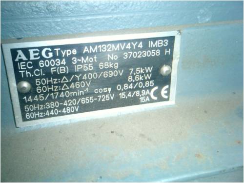
Let's assume a 50Hz system. We get the following figures for that: in star : U=690V; I=8.9A ; P=7.5kW in delta: U=400V; I=15.4A; P=7.5kW From the above, we can deduce that (for one single, disconnected phase, i.e. neither star nor delta) phase voltage = 400V and phase current = 8.9A; then phase 'resistance' (yes, I know, should really be impedance...) becomes 400/8.9= 45 ohm; we will use that phase resistance (45ohm) to verify the next calculations: We can now calculate the 'source impedance' (rather: sink impedance, in the case of a motor): in star : R=U/I= 690/8.9 = 77.5 ohm (verification: 45*1.73=77.9ohm) in delta: R=U/I= 400/15.4 = 26 ohm (verification: 45/1.73=25.9ohm) The ratio between these two impedances is nearly perfectly 3: 77.5/26=2.97 (note that in the above I assumed that impedance is purely resistive, which of course it isn't; the resistance of one single phase was 1.85ohm for this motor... the rest ( sqrt(77^2-(1.85*1.73)^2) ) is inductive reactance.) But still, I hope you see the main point, how it varies with delta vs. star: in star, voltage goes up by 1.73 times; in delta, current goes up by 1.73 times; assuming constant power (i.e. comparing apples with apples), this means the difference in source impedance is a factor 3. [quote=Oztules]I'm not sure you are correct with your star resistance being 1.73xR.[/quote] Note that I meant with R the -phase resistance-, i.e. the resistance of one single phase. In star the -source resistance/impedance- of the 3 phases together would be 1.73 * R; in delta, it would become R/1.73. The ratio is 1.73/(1/1.73) = 1.73^2=3. I believe the thing to be conclusively proven by just looking at the nameplate data of any old 3-phase motor... ? At least, that's how I understand it. But I don't claim to be an expert in 3-phase power calculations. On the contrary. If I'm wrong, please correct me. Peter. |
||||
| oztules Guru Joined: 26/07/2007 Location: AustraliaPosts: 1686 |
No... not misunderstanding, just not agreeing. Delta has 1.5 times the current of a single phase... yes sticking by my post above. The name plate only suggests that they can multiply and divide properly. If we jack up the voltage x 1.7 to go from delta to star (and we both agree that star is 1.73 x delta) we have to divide the current by the same amount, multiply them out...to get the same power rating... no more cunning and no less..... or maybe just maybe they agree with me too. If you look at my example above, the current for star is I=E/R... = 1.73/2 = .865Amps in delta its 1/.667=1.499A The ratio just happens to be 1.499/.865= 1.73 Funny how using the .667R and the 2R figures get the right result.. for the right reasons. Delta gets only 1.5 times the current of a single phase group... not 1.7... just cant do it. It is coil group 1 plus an equivalent current through twice the resistance of the other two phases... so half the current....= 1.5 times a single coil group Star current must run through twice the resistance (cu loss), and that can't be waved away through anything short of resonance... and we don't have that at low frequencies, but the relationship remains the same regardless of frequency. The vector addition is for voltage... which turns out to be 1.73 times a single coil. The current has to wade through two coil groups resistance. It can't avoid this.... so 1/2 the current. Here is a quote from ULR "For a given coil resistance: - Y has all the current passing through two coils at all times. For a small fraction of the time all the current is in one coil and all of it is split (unevenly) between two in parallel. - Delta (except momentarily near certain crossovers) always has the current unevenly split between the parallel combination of one coil with the other two in series, with two-thirds through the single coil. - Jerry rigged has all the current unevenly split between several single coils. At any given moment, in delta connection, one coil produces a given voltage (above the cutin voltage) while the series combination of the other two ALSO produces that voltage (and half the current of a single coil). So the delta connection contributes half again the current of a single coil. " and I tend to agree (coz he's agreeing with me) 
......oztules (whom Dinges is thinking is the scumbag of the universe) Village idiot...or... just another hack out of his depth |
||||
| Dinges Senior Member Joined: 04/01/2008 Location: AlbaniaPosts: 510 |
See at the very bottom of this link: http://www.allaboutcircuits.com/vol_2/chpt_10/5.html That clearly says: 'for delta circuits, Iline=1.73*Iphase'... It does *not* say 1.5 times... [quote=Oztules]Delta has 1.5 times the current of a single phase... yes sticking by my post above.[/quote] If that doesn't convince you... I don't know what will... The above goes for perfectly balanced star and delta in 3-phase distribution systems, with perfectly sinusoďd waveshapes. I'm not sure how the presence of (non-linear) rectifiers changes the above 'ideal' case. I can't really argue this point any more, as I'm at the limit of my knowledge with the previous post and this one. But if you think I'm wrong, could you specifically point out where I made a math error in my previous reply? I'd appreciate that. Because I can't find any errors there. Maybe there's an implicit assumption I (or you?) are making though. Note that I was talking about the case of constant/equal power in star vs. delta. [quote=Oztules]Delta gets only 1.5 times the current of a single phase group... not 1.7... just cant do it.[/quote] [quote=Oztules]Delta has 1.5 times the current of a single phase... yes sticking by my post above.[/quote] See my above remark... P=U*I=constant... if U goes up by 1.73 in star yet current only goes down by 1/1.5 in delta (as you claim)... Then P= 1.73/1.5 = 1.15 != 1... Power in delta would then not be the same as power in star. So, where did the rest of the power go? If I'm wrong, it's probably something big that is staring me right in the face and I just don't see it... In which case you'll be only too happy to publicly flog, err, correct me... Peter. |
||||
| The Back Shed's forum code is written, and hosted, in Australia. | © JAQ Software 2026 |
