
|
|
Forum Index : Windmills : 36 slot stator and a long way to go...lol
| Author | Message | ||||
methanolcat Newbie Joined: 05/08/2008 Location: United StatesPosts: 9 |
wow, good posting, lots of detailed discussion. One thing I would like to add here though is that if all coil ends are brought out of the motor conversion and put into a box as I have done then there are a lot more RPM/ voltage possibilities just by changing connections. That was my plan, high voltage for heating during winter (lots of wind) and lower voltage during the summer for battery charging. The top half of the following sheet show all of my possible connections and voltages for each through various RPM's. Disregard the lower half those numbers are for an auxiliary winding I put in as well for ? RPM sensing, powering a control circuit/ whatever. 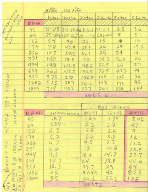
As can be seen paralleling or even tripling the windings will provide lower voltages and be able to handle higher current without overheating as well as giving you more RPM and prop diameter options. Changing the winding configuration is pretty simple using terminal strips and jumper wires. Pick your charging voltage, match your prop diameter, RPM and available power in the wind, remembering max output of around 4,000 watts and set your furling accordingly and your all set. Matt Matt |
||||
oztules Guru Joined: 26/07/2007 Location: AustraliaPosts: 1686 |
Welcome downunder Matt, Yes, that gives you some very useful flexability, but I notice from this picture, that it is not for the disorganised 
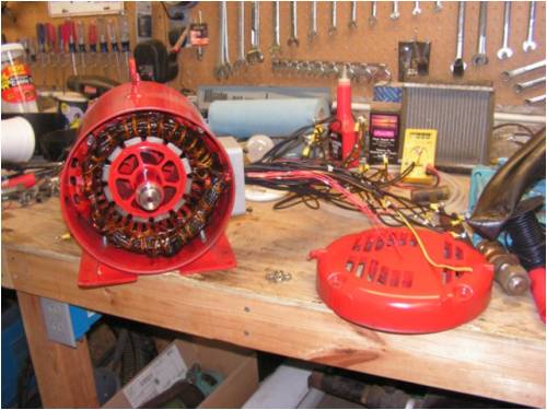
Thats a serious wiring loom you have there. I would forget to file the wiring code where I would ever find it again. 
I think it is an excellent and professional conversion you have done there. Nice work indeed. 
..........oztules Village idiot...or... just another hack out of his depth |
||||
| Dinges Senior Member Joined: 04/01/2008 Location: AlbaniaPosts: 510 |
Oztules, the amount of energy available in the wind is limited too. Like you I wouldn't care much for efficiency when it's blowing a gale but I *would* when the leaves barely move and I desperately need every watt that I can (because if I don't I'd have to start the diesel genny to recharge the batteries). Your argument (not just yours, I've seen it a lot over the years on FL) that we could simply make the blades a little larger to compensate is of course true. But there are costs involved in that: larger blades needs stronger bearings, stronger towers which need larger foundations and stronger guy wires. In short, it's a road that costs extra money. It's a bit like 'work smarter, not harder'. Will you work harder (larger windturbine) or will you work smarter (reduce losses). Both have the same effect: more watts into the batterybank. Working harder (bigger genny) will cost money and effort, a genny with higher overall efficiency will only take effort once (during the design and building phase). I fail to see why the only efficiency we should take into consideration is related to electrical efficiency (low impedance generator). A watt lost is a watt lost, whether it's lost in an inefficient turbine blade (3 planks for blades), lousy bearings, a gearbox (if present), stator loss, copper loss (electrical resistance losses), losses in the rectifier, the wires, the conversion in the batteries from electrical to chemical energy and the reverse, etc. A windgenerating system is a system, where everything interacts with everything. To optimize for one efficiency (least resistance) and ignoring the rest seems unwise to me. As said before, a watt lost is a watt lost. Frankly I couldn't care less exactly *where* I lost that watt, all I know is it is no longer useful to me, and *I want my watt back!* (Dinges said, in a Maggy Thatcher voice). A watt lost in iron losses is just as precious to me as a watt I lost in copper. Again, I fail to see any distinction here. I disagree with the reliable part. Given some proper engineering I doubt the axial flux would have to be any less reliable than a plain induction motor. One shouldn't extrapolate shade-tree shoddy workpractices (not to mention the practice of running axial fluxes far above their ratings due to improper furling) to professionally designed and constructed MegaWatt turbines. (there are exceptions but many axial fluxes I've seen look like they wouldn't be harmed with a little more forethought and care when designing and building. There are good exceptions though. And though motorconversions are usually built to a higher standard than axial fluxes (simply because the people who *can* build conversions are likely to have the tools (lathe, mill, calipers, micrometers) and know how to use them, yet I've also seen one or two conversions that made me cringe.) Of course the windsupply is unlimited (at least when it's blowing) and wind is free. However, extracting wind and turning it into energy that's useful to us isn't. Larger blades cost more money to make and induce more stresses in the rest of the construction so everything else would need to be beefed up too. It still makes sense (within limits) to strive for best efficiencies in the system without having to resort to such stop-gap 'solutions' as simply making everything 10% bigger. And as I've said before, I fail to see the distinction you again make between iron loss and copper loss, or, for that matter, any other kind of loss in the windgenerating system. This is exactly what I've been saying previously; when copper loss = iron loss, the sumtotal of the generator losses should be at a minimum. I tried to illustrate this with my example of the two extreme cases (near-zero flux vs. infinite flux). I'm a bit surprized by your above remark, as (to me) it seems to be opposed to everything you've said before in your reply and the replies before. I can, however, fully agree with your remark; it's basically what I've been trying to say all along. 
This sub-discussion is getting far away from the original thread topic. It's an interesting discussion though. If we feel like continueing it maybe it's best to start another thread, unless we can 'wrap it off' quickly. |
||||
| Dinges Senior Member Joined: 04/01/2008 Location: AlbaniaPosts: 510 |
Nice conversion indeed! I don't recall reading anything about yours yet ? Looks like a 12 pole with skewed stator. Impressive. Yep Methanolcat, and that's exactly how I intend to rewind the 10 hp conversion too: http://www.anotherpower.com/gallery/album68/blue_monster_wir ing_diagram It gives a lot of extra options, as opposed to hardwiring everything and then sealing it. The downside is, of course, that the wiringbox will become quite impressive :) Three phases with 6 coils each, each coil having two wires... 36 wires in the connection box. Do you happen to have a closeup of the inside of the connection box ? I'd be interested in seeing how you solved the practical problem of handling all those stator wires and connecting them up in the configuration of your choice. Edit: that is, if you've in the mean time managed to cram it all in the connection box... :) |
||||
| oztules Guru Joined: 26/07/2007 Location: AustraliaPosts: 1686 |
Dinges I will start another thread under rants tonight, where we can explore it more thoroughly. "I'm a bit surprized by your above remark, as (to me) it seems to be opposed to everything you've said before in your reply and the replies before." We will find it fits the argument perfectly when fleshed out. Partway through painting the chainsawn blades with epoxy paint... can't stop long, and as you pointed out hardly fair on crazie. Later... ..........oztules Village idiot...or... just another hack out of his depth |
||||
| methanolcat Newbie Joined: 05/08/2008 Location: United StatesPosts: 9 |
Dinges, ""It gives a lot of extra options, as opposed to hardwiring everything and then sealing it. The downside is, of course, that the wiringbox will become quite impressive :) Three phases with 6 coils each, each coil having two wires... 36 wires in the connection box. Do you happen to have a closeup of the inside of the connection box ? I'd be interested in seeing how you solved the practical problem of handling all those stator wires and connecting them up in the configuration of your choice. "" 36 wires is correct for the main windings, keep everything neat, number every wire, use terminal strips so you never have to move any winding wires (use jumpers). My box is 10" X 10" X 4", plenty of room as can be seen. 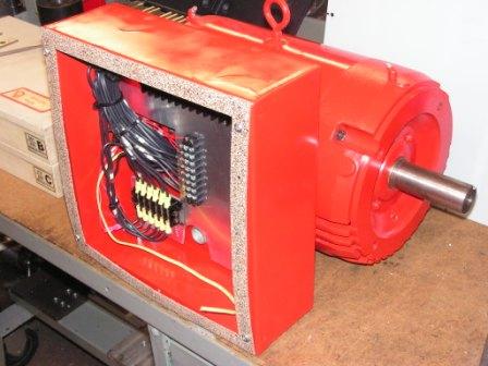
The second pic shows an example of where the jumpers would be for 1 star and 1 delta using relays and also placement for a star/ delta switching circuit which could be powered from the auxiliary windings. Many more pictures and info on this project under my name on FL. Matt Matt |
||||
| methanolcat Newbie Joined: 05/08/2008 Location: United StatesPosts: 9 |
Many thanks up-over oztules ""Thats a serious wiring loom you have there. I would forget to file the wiring code where I would ever find it again."" I'm going to stamp all of the star and delta wiring configurations on the inside of the wiring box cover, as long as I don't lose the cover I think I'll be alright. I don't have this baby flying yet as there was a tower malfunction last fall and I had back surgery this spring but I hope to get her up before this winter. Much testing has been done though and everything is looking good so far. I'll post a complete story on it when I get it done, so be looking for that. There is also a much larger generator (25hp motor conversion) currently in the works (40- 2 X 1 X .5 neo's), it probably won't be finished until next summer though. Matt Matt |
||||
| oztules Guru Joined: 26/07/2007 Location: AustraliaPosts: 1686 |
Oh dear, I suspect there will be a certain gentleman from the Netherlands with a degree of rotor envy .... 25hp... yikes. Knowing the standard of your work, I can't wait to see it. Your first attempt was a beauty, the second will be well worth watching.... I will be looking out for it Matt. "I don't have this baby flying yet".... so we don't know how the dump load controller performed then? It is something CraziestOzzy will need to address as well... roughly the same size. ..........oztules Village idiot...or... just another hack out of his depth |
||||
| Dinges Senior Member Joined: 04/01/2008 Location: AlbaniaPosts: 510 |
Darn. My 10 hp is obsolete even before it's finished. 25 hp ?! It's hard to keep up with the Joneses... Impressive connection box. Room for star/delta switching too. Nice. I was hoping you managed to cram it all in the original connection box but that would have been too much to ask. 40 magnets for the 25 hp looks a bit little though; I managed to cram 36 2"x1"x.5" magnets into the 10 hp; I'd expect you should be able to cram a lot more magnet into the 25 hp motor ? See also the discussion with Oz about achieving as high flux density as possible. I know Zubbly had a 25 hp motor lying about and was contemplating using it. My hat is off to you, I will not be going any bigger than the 10 hp. I can still lift and drag the 10 hp by hand, can't do that with a 25 hp (without back pain). That, plus the fact that my mate had plenty of trouble machining the 10 hp rotor. It was at the limits of his lathe, mill and grinding machine. So no bigger gennies for Dinges. 
Looking forward to reading more about that project of yours. |
||||
| methanolcat Newbie Joined: 05/08/2008 Location: United StatesPosts: 9 |
Oztules ""I don't have this baby flying yet".... so we don't know how the dump load controller performed then? It is something CraziestOzzy will need to address as well... roughly the same size." No, it's not flying yet but I have bench tested the load controller and had it hooked up to a small windmill (8 foot diameter blades hooked up to large servo motor) and it worked well, may have to make some adjustments for the bigger mill though. Matt Matt |
||||
| methanolcat Newbie Joined: 05/08/2008 Location: United StatesPosts: 9 |
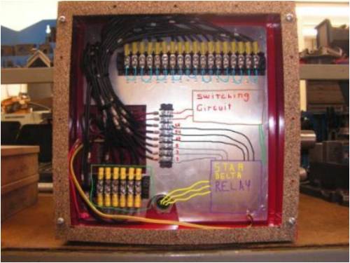
Here is a pic of the controller, still need to mount it in a box with all the SSR's and a heat sink. 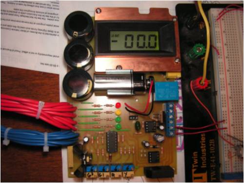
Matt Matt |
||||
| oztules Guru Joined: 26/07/2007 Location: AustraliaPosts: 1686 |
Wow Matt, looking very nice. Did it drive the ssr's ok, or do they load it up too much. or put another way, did you or will you get away without a buffer stage? .........oztules Discussion on this controller is here link Village idiot...or... just another hack out of his depth |
||||
| methanolcat Newbie Joined: 05/08/2008 Location: United StatesPosts: 9 |
OZ, I guess I'm not sure what you mean. Matt Matt |
||||
| methanolcat Newbie Joined: 05/08/2008 Location: United StatesPosts: 9 |
Dinges, "40 magnets for the 25 hp looks a bit little though; I managed to cram 36 2"x1"x.5" magnets into the 10 hp; I'd expect you should be able to cram a lot more magnet into the 25 hp motor ? See also the discussion with Oz about achieving as high flux density as possible." It's going to be 20 pole, 60 coils, large diameter. I estimate around 6,000 watts max capacity using 40 mag's. I guess I could get 20 more and make the poles 6 inches long, I would estimate it to put out around 9,000 watts max then. I guess my main goal at this point in the larger one is high voltage output at low RPM. My blades will be around 20 - 24 foot diameter with a torque pitch controlled hub, so with blades that size and I don't want to use gearing I need to construct a large diameter gen with plenty of poles and coils. Matt Matt |
||||
| oztules Guru Joined: 26/07/2007 Location: AustraliaPosts: 1686 |
Matt, From my last guess, you are using about 3k3 for the pull up resistors. These provide the power to drive the ssr's. Was it enough to drive three in parallel or did you need to decrease the 3k3. If you did , did the 393 get hot or was 3k3 alright to drive the three ssr's and the led. 24 feet diam..... wow. remember to take the camera with you when you start this monster. ..........oztules Village idiot...or... just another hack out of his depth |
||||
| methanolcat Newbie Joined: 05/08/2008 Location: United StatesPosts: 9 |
oztules, Yes still using 3k3 for pull up's, the ssr's draw amazingly low current and only 5 volts to turn them on. I'm guessing they are using optocouplers in the ssr's which don't draw much anyhow. The 339 gets warm but I also designed up a separate temp control circuit that will turn on a fan to ventilate the enclosure. I had thought of trying to place a small heat sink on top of the 339 just to make sure it didn't get too warm (longer life). What is a buffer stage and how would it work? I had also considered using 4 small transistors one for each set of ssr's if needed that would remove some load from the 339, that would work as well, am I right? There is a lot of electronics info to take in but I am constantly researching and learning new things every day. I'm learning a broad range of the field but mostly concentrating on power control systems. I also have a basic stamp 2 that I am learning to use, maybe implement it in my controls at some point or another (probably way down the road maybe attempt mppt, not real concerned with that at this point though, still have much to learn). Technology isn't it a great thing. And yes, I'll take lot's of pic's. I want to start a discussion sometime on this bigger gen. I'm planning to build, still tossing ideas around at this point. Matt Matt |
||||
| oztules Guru Joined: 26/07/2007 Location: AustraliaPosts: 1686 |
Matt "What is a buffer stage and how would it work? I had also considered using 4 small transistors one for each set of ssr's if needed that would remove some load from the 339, that would work as well, am I right?" You have answered your own question. The four transistors will be / are the buffer stage. Buffer stage is just a fancy way to say "isolate the load from the driver", the transistors do just that. They take the "weight" of the load off the 339. It will still have no effect until you change the 3k3 to maybe 4k7 or higher. It is this set of resistors that is heating up the 339. If you like, you can try 4k7 and see if the ssr and led still trigger. If the 339 is still not to hot to hold your finger on, you are less than 60 degrees C, so it should be fine even without the buffer stage (4 x transistors stage). Discussion on the 25hp should be interesting. Look forward to it, but you are an old hand at it now 
.........oztules Village idiot...or... just another hack out of his depth |
||||
| Dinges Senior Member Joined: 04/01/2008 Location: AlbaniaPosts: 510 |
Matt, I had a look at the story of your construction of the conversion. Very impressive. Somehow I managed to miss this story at the time. One thing about the solid-state relays (SSR) though. I can't really find out from your story whether you will be heating with the raw AC or be using DC, but keep in mind that most SSR can only switch AC, as they need the zero-crossing of the waveform to switch off. Should you use DC (I can't see any advantage for converting to DC for heating purposes anyway) the SSRs may turn on but won't be able to turn off, unless you use SSRs that are specifically designed for this. SSRs are really very nice. Have a box of Opto22 ones here that switch on with just 3V @ 1mA. They leak much more in the off-state than mechanical relays but in applications where that isn't an issue their simplified driving is simply a joy. 16A/380V switched by less current than it'd take to light a LED. |
||||
| GWatPE Senior Member Joined: 01/09/2006 Location: AustraliaPosts: 2127 |
Hi dinges, I have some 30V@100A DC SSR's. These are good value for isolated high side low frequency switching. Gordon. become more energy aware |
||||
| The Back Shed's forum code is written, and hosted, in Australia. | © JAQ Software 2026 |
