
|
|
Forum Index : Windmills : Making blades with a ChainSaw
| Author | Message | ||||
| GWatPE Senior Member Joined: 01/09/2006 Location: AustraliaPosts: 2127 |
Hi oztules, I am a great fan of the "KISS" principle. I do sometimes go overboard in complexity to strive for the best result, and usually revert back to KISS when reliability becomes important. Gordon. become more energy aware |
||||
imsmooth Senior Member Joined: 07/02/2008 Location: United StatesPosts: 214 |
This is for Gordon or Oztules, or anyone else that wants to respond. I am preparing my gig for cutting my blades. I am going back and forth between doing a straigth line for the cut, going from 3deg to 16deg linearly, and from doing a non-linear increase in the pitch according the the blade calculator. It is certainly easier to cut along a line, and easier to setup; but, is there a real difference in performance? |
||||
oztules Guru Joined: 26/07/2007 Location: AustraliaPosts: 1686 |
not enough to worry about if my results are any thing to go by. ..........oztules Village idiot...or... just another hack out of his depth |
||||
| oztules Guru Joined: 26/07/2007 Location: AustraliaPosts: 1686 |
Been thinking about this. If you have a cogging machine, or significant iron loss, then perhaps more attention to the root should be paid for better start-up. If for an axial flux, then don't bother with the root area, you won't need the start up torque anyway, and it will reduce drag higher up. (very marginal I think). That said, we used a straight profile on the set we built for the AWP, and it starts a little later than it did with the deep rooted AWP glass blades, but develops more power in the upper ranges then the original blades.... swings and roundabouts I guess. The AWP has significant iron drag, but no cogging. For the first set, straight is the ticket, as if you have too much curve going on, it may bind the chainsaw blades a little. ..........oztules Village idiot...or... just another hack out of his depth |
||||
niall1 Senior Member Joined: 20/11/2008 Location: IrelandPosts: 331 |
hi all ...looks like i,m the culprit with the chainsaw in ireland stealing oz,s ideas so i better own up 
.. a few of us tried having a go at oz,s idea one evening with hugh during his last course in galway (kind of entertainment for grown ups with beer)...the gig was very rushed but we managed a few cuts which showed its potential ,and more weirdly you can cut a curved blade which definetly dosent come to mind looking at a chainsaw , a few ideas were bounced around about add ons for the saw ......also oz mentioned using stronger gigs so i went about making some after the course ,simpler ones would have been proobabely be just as good ...i tried for as big an angle at the root as possible but i think compromising a bit there would be a better idea , i think the chainsaw would really come into its own for say making props over 2 m next idea oz ??............ niall |
||||
| GWatPE Senior Member Joined: 01/09/2006 Location: AustraliaPosts: 2127 |
Hi oztules, looking at the above posts and Hugh's involvement, and blades being produced with a deep chord at the blade root would suggest some value in going this way. These irish blades were for an axial flux mill. I suppose, that is, if you make a jig, you may as well make blades to the best formulae. Gordon. become more energy aware |
||||
| niall1 Senior Member Joined: 20/11/2008 Location: IrelandPosts: 331 |
i should have mentioned that i tried to follow hughs guidelines for the my 3.6 m machine , cutting these angles down to the root was fairly straight foreward , easy even ,i,m not sure but a very deep cord at the root might force you to compromise on its ideal angle niall |
||||
| oztules Guru Joined: 26/07/2007 Location: AustraliaPosts: 1686 |
Your right of course Gordon, if you are going to make a jig, it may as well be the best you can do..... except if you only intend to make a single set, and you have an axial. My jig was a five minute affair, the Irish version is very much more sophisticated and would have taken a deal of time and effort to achieve. The difference in power production is hard to guess at, Dan is happy with his results, (and so am I ) and the AWP works better with the simple formula at power. The difficult thing to gauge with the AWP is that Jamie has heaps of wind, so it may be a poor comparison for normal machines, although on calmer days, it does very well also. However, if your serious about it, then a proper twist is easy to achieve, but longer to set up for. Once set up of course, it is only a matter of how much dust and smoke you can stand as to how many you make..... over here there was plenty of wind to blow the smoke and dust away, and so it was not a consideration. ............oztules Village idiot...or... just another hack out of his depth |
||||
| imsmooth Senior Member Joined: 07/02/2008 Location: United StatesPosts: 214 |
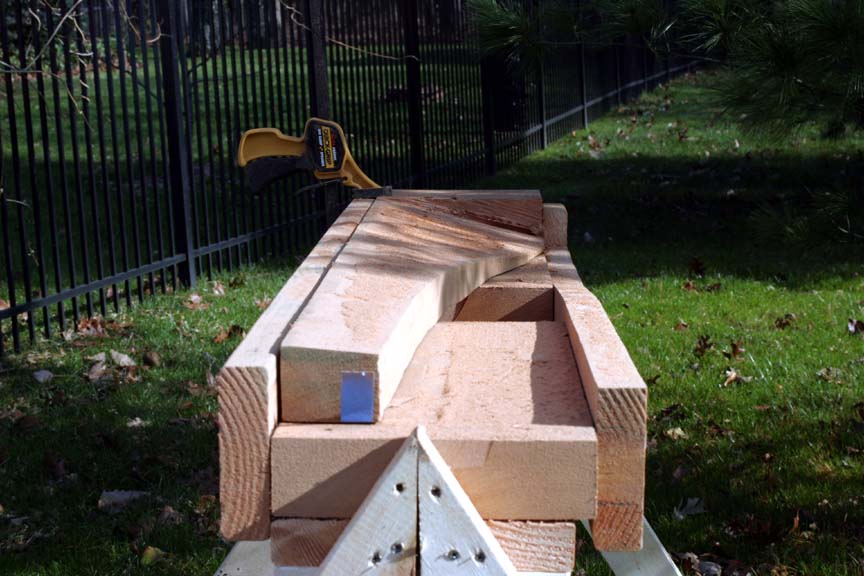
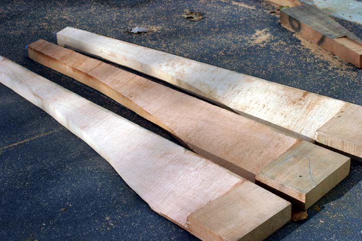
Oztules, your legacy will live on. I just carved the profiles for three blades using a chainsaw. I felt like an ice sculptor artist. I will have to get two more block of cedar since the weights before I plane and sand are 9.7, 9.5 and 7.5lbs. I would like to get two closer to the 7.5lb weight. I spent a lot of time setting the theoretical profile using a complex curve rather than a tapering line. Here are the pictures. 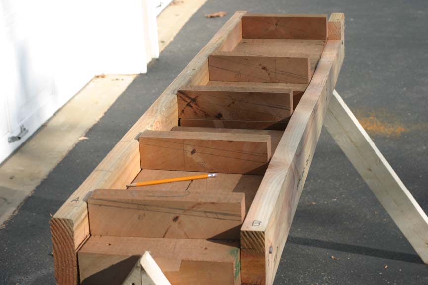 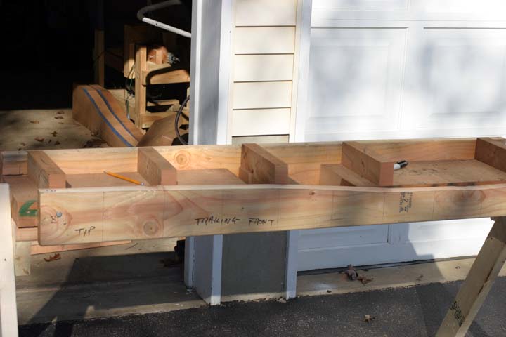 
   |
||||
| oztules Guru Joined: 26/07/2007 Location: AustraliaPosts: 1686 |
I'm keen to see them finished. Don't get too excited about the weight differential, you may find that you can get a little closer when you tidy them up some. Heavy, or light blades, makes little difference to overall performance. A light set may accelerate faster but it looses faster too. Final balancing will sort out the differentials anyway. It doesn't take long to go from rough to finished profile, so do-em all, you may be surprised how close they come out.. and good practice too. The complex curve makes it slightly trickier, but everyone else but me seems to be able to do it. Niall did that too. I don't think I would want to try to get the two profiles the same  straight was easy. straight was easy.
I would still tend to leave the taper until I had cut the twists... just to keep it steadier in the jig.... although my jig was pretty rickety I guess. If your chain was tight and sharp, it should have eaten that pretty quickly.. Well done, looking forward to seeing them finished. ......oztules Village idiot...or... just another hack out of his depth |
||||
| niall1 Senior Member Joined: 20/11/2008 Location: IrelandPosts: 331 |
great work and pics imsmooth ! getting stuck right in there is the only way to figure how its done and every run you do teaches you something you didnt know before..its nice to get the optimum curve in the blade to... funny this is my old blades have a constant 4 angle all the way down to the root same dimensions no twist.. and i was really surprised how well they worked , a bit slow to start maybe but when they got going you wouldnt want to be standing next to them so i,m in no rush to change them ,i think i just like the look of a twisted blade (maybe i need to get out more) ....like oz says finish yours off ,you,ve just got the delicate work left (if wont take long) and you,ve got a result ! niall |
||||
KarlJ Guru Joined: 19/05/2008 Location: AustraliaPosts: 1178 |
any chance you guys can get together and write a book? Truly awesome work congratulations. Karl Luck favours the well prepared |
||||
| KarlJ Guru Joined: 19/05/2008 Location: AustraliaPosts: 1178 |
BTW very intrigued as to your technique for pumping back into the grid, any chance you could explain? Karl Luck favours the well prepared |
||||
| oztules Guru Joined: 26/07/2007 Location: AustraliaPosts: 1686 |
Karl, a quick version goes like this. I used a 4pole 1 phase induction motor in my latest grid driver. It is about 1500w, just previously, I used a 4pole 7kw induction motor... anyway it does not matter which, but the 3 ph is smoother and has better results, but the system is the same... dead simple. We'll use the single phase one for this. I direct coupled a motor to a 4kw 36vDC brush motor. I ran the induction motor connected to the grid, to check it's direction, and wire the DC motor for the same rotation. I then removed the run capacitor from the motor. This is to stop self excitation should the grid drop out.... islanding I believe it's called. (and it drops out all the time over here so was relevant). Next I hooked up a 275 amp dc motor drive to the battery bank. Started the DC motor to drive the induction motor. when I guessed it was around just under 1500 rpm, turn on grid to the induction motor. It pulls the dc motor up to grid HZ-slip.... approx 1440rpm. I then slowly increase the rpm on the dc motor with the motor controller, and the sound of the hum changes, and the DC motor starts to dig in. We are now driving the asynchronous motor, and the grid is magnetising it at grid frequency. The rotor is now over 1500rpm (synchronous frequency) and drives EMF into the grid. We turn the DC motor up further, and watch the meter run the household power, and run the meter backwards. We drive a bit harder, and it spins backwards quite quickly, as well as driving the house. If the power grid fails, the output stops immediatly, as the magnetising current disappears, and the emf stops, the DC motor is now unloaded, and just spins the ac motor for no effect.... islanding. This is exactly how the grid tied windmills work (without the windy boy inverters)... just replace the DC motor with your favourite windmill with a approx 13:1 step up gearbox and 20 foot blades, and a bigger 3ph motor. (they use a soft start system to interface, but they are also pushing out lots more KWH than this experiment. Hope that helps. Village idiot...or... just another hack out of his depth |
||||
| KarlJ Guru Joined: 19/05/2008 Location: AustraliaPosts: 1178 |
so please tell me why we are not all building grid tied windmills if it is this simple and (appears) cost effective. It doesn't appear too automated in your system requiring a deal of user input. Excuse my ignorance but could you do this on a small scale? I'm not really up to speed yet on the induction theory. Your mill uses permanent magnets right? and an induction modor induces a mangnetic field in the rotor instead so no brushes are required and no permanent magnets and its output is regulated by the frequency of the grid right? So what is stopping you clever fellas coming up with your own grid connect induction system? You have the chainsaw for the 20 foot blades, wouldnt be hard to make them a little tougher with a routed channel full of carbon uni tape and some glass over the top for weather resistance. Luck favours the well prepared |
||||
| oztules Guru Joined: 26/07/2007 Location: AustraliaPosts: 1686 |
Hi Karl, I answered a similar question regarding the breezy 5.5kw home grid connect induction "kit".. over here I fit the category, and the blades will be fine without any impregnation.... just wood is as good as you require.... probably as good as it gets if the truth be known. The soft start system is simply some hefty chokes in series for a second or so, then switched out of circuit. Because of startup gearbox, torque requirements, and the associated losses when running 18' is probably as usefully low as you can sensibly go. This a a fair handful of machine... not for everyone. .........oztules Village idiot...or... just another hack out of his depth |
||||
| Dinges Senior Member Joined: 04/01/2008 Location: AlbaniaPosts: 510 |
Oztules, that was an interesting explanation of yours on FL. One thing that has always bothered me about the Breezy is the mysteriosity that surrounds the controller. But from your description I understand that all it does is compare motor/generator frequency to grid frequency, and then connects the motor to the grid; first via chokes for a few seconds, then directly? That all? An off-the-shelf PLC with a simple program would be all that is needed in that case. From your playing around with the 275A motorcontroller, DC motor and 3-phase induction generator, it seems it should be a piece of cake to program the 'human intelligence' (the sequence of actions you perform with the DC motor controller and induction motor/genny) into a PLC. But I wonder: why the chokes; to limit inrush current? If so, are the chokes really needed if the turbine is running at, say, 1450 RPM (just before connecting) and then connects to a grid which is at 50Hz (1500 RPM)? And I don't recall you using chokes in your experiment with the DC-motor/controller/induction generator? Probably I'm missing something here... Personally I'd love to see a block diagram or schematic of exactly what this famous Breezy controller entails. From your remarks it seems to be blown out of proportion. Guess the unknowness/secretiveness of it is part of its mysterious 'charm'? Then again, if the controller is anything like the rest of the 'Breezy 5.5', I doubt there'd be much worth looking at. Just had a look again at the Breezy website... building such a turbine from an off-the-shelf motor with gearing seems much easier for the average bloke than building an off-grid windgenerating system. I wonder why people actually need plans to build one... not to say it's easy; will take a lot of physical labour. But there seems to be very little specific knowledge required to make it work: take a 10hp motor with reduction, slap on a coupler of suitable rating, weld a frame, install pillow block bearings, insert shaft, slap prop on, raise tower... Don't want to sound too negative but I can't say I've seen a lot of sophisticated constructions on the Breezy website. And IMHO this mystery game of the controller has lasted long enough. But who am I. Curious Peter. |
||||
| oztules Guru Joined: 26/07/2007 Location: AustraliaPosts: 1686 |
Hehehe, what's in the box he says..... Not as much as I would like to see actually. As you can appreciate, I cant publish their stuff on the web, it would be a breach of faith (nevermind the legal stuff), and no circuits are supplied anyway. They are their property rights. That said, it is not really worth messing with their black box, as it is simply a simple pic to hook up when conditions are right, disconnect when they are not. Shut down is case of grid loss, or over speed.... and from memory that's about all it tries to handle. I feel that in this instance, getting up to this size, I would add the following. 1. Over wind speed averaging shutdown (from anemometer), 2. Vibration sensor shutdown (if you lose a blade or guy wire at worst, or something less severe.) So some simple analogue sensors (freq, voltage, vibration, and windspeed voltage comparator/averager (window comparator perhaps better), and a few relays and a vibration sensor to detect unbalance and you have a better system (theirs is very sufficient as it is), but with playing with the larger ones over here, this is how I would do it. They sound more complicated than they are. The voltage sensing can be as simple as a modified Ghurd controller. Use under/over voltage as a stop condition. Frequency metering is done by nearly everyone here (except me actually). Tone decoder chip out of your phone will probably suffice to detect 50hz... etc.... shaft not AC is the important one.... AC as well if you want to be fancy for over freq shutdown. But the shaft is the important one. A window comparator with r/c time delay from the anemometer will suffice for your wind speed window device (range to have the brake released) No point rotating the gearbox, if no-one is paying for it. It is not like the battery things, where you treasure every watt however you get it. These things either generate heaps of power you couldn't hope to store, or turn off. The lower power ranges are not viable or sensible to use. Bank the power and be happy. You'll get more useable power than the battery setup anyway. Vibration device can be a simple mercury switch driving a latched relay (if set, we don't want restart) If we keep capacitors well away, then grid loss will stop the mill (because the brake will come on if it looses power.) The frequency sense (shaft speed) and voltage comparators would likely go off at almost the same time. If Caps are used for power factor correction, then the freq and voltage comparators will catch it. (the mill will spin up, and freq will rise as it tries to find a balancing rpm for the self excitation to work at load, so revs will rise, and voltage will swing about the place. So one or the other or both (most likely) will turn it off. I prefer a spring loaded normally on brake, and hydraulically pushed off, held off by a normally open hyd valve. Any power loss would loose pressure, and the brake will come on reasonably gradually (rather than trying to break the gearbox with the electric brake). I would build the brake onto the prop shaft like the ones over here... no chance of breakage. (motor/pump and small ram out of a forklift is what I have for this part. That about covers the wish list I think. Simple stuff. Their blades are sensible constant pitch, constant chord... simple as it gets. Very well done actually, as that design will effectively help stall limit after a certain point (forgive me Sparweb, I don't know how else to describe it). Sparweb could probably explain the how and why. The chokes would not be necessary on little ones like this, but work as you describe, theirs do not use them either as I recall. By not using the coupler, the unit can be considerably smaller as most of the space is used up by the extended shaft and coupler. Not required for direct braking (using a truck drum or similar)... but messier than thir electric type (with torque coupler) Furling should not be required, as the wind averager will turn it off if conditions are too bad, and you can use all the power you can deliver with these things at windspeeds less than the window you set. eg, If it exceeds 35mph for 15 seconds, then shutdown. The window comparator will start it up again when conditions are met. Anything else you wish to know about these things? I may do one of these yet. For anyone else pondering doing this style of thing, I say this. It would be extremely short sighted to not buy their book, and if you are not an electronics person, their controller. There is a wealth of experience in there from people who HAVE done it, and very successfully. In the scheme of things, the book in particular are very very cheap adjuncts which will all but guarantee success, if you go it alone, best of luck. It is simple.... but so are battery wind turbines, and first timers NEVER get it right first time on their own (this includes the Dans, Hugh and dare I say it M Jacobs, and this is not a toy project.. it is an expensive project. The book and controller are probably cheaper than the bits of string and turnbuckles you'll use to hold the tower straight. .........oztules Village idiot...or... just another hack out of his depth |
||||
| Dinges Senior Member Joined: 04/01/2008 Location: AlbaniaPosts: 510 |
Thanks Oztules. For a while I've been pondering what it'd take to build a grid-connected turbine. There's some information here too, too bad it's only in Dutch (Belgian guys): http://www.windmolensite.be/ Ok, first something else I need to get off my chest... [start off-topic rant] (rant deleted) [/rant] There. I feel better now. 
For a while I've been thinking about this grid connection thing. I'll try to set up a list of requirements I'd want in my (hypothetical) grid-connected turbine, and how I'd implement it (flowchart). Will post something on this forum for discussion when I have something worthy for submission here. Still have a lot of things to ponder over. BTW... instead of inductors... one could use lightbulbs or resistors in the line to more softly connect the motor/generator? Bit like the trick of a series lightbulb when powering possibly defect electronics appliances. The downside of lightbulbs is that they can burn out, of course. The Belgians in the link above used 3-phase DIY triac-controller. BTW, a few weeks ago I saw a *very* nice 3-phase industrial thyristor phase-angle controller which would be just the ticket... United Automation HFM36A... 370E though. http://www.farnell.com/datasheets/123079.pdf Peter. [quote=oztules]what's in the box he says...[/quote] Mr. Schr�dinger could not tell. |
||||
| oztules Guru Joined: 26/07/2007 Location: AustraliaPosts: 1686 |
Dinges, here is the poor mans grid connect kit complete but for batteries: 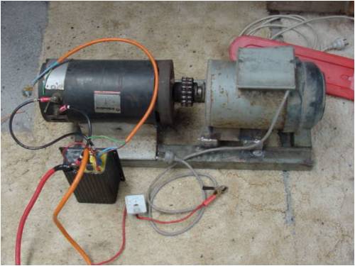
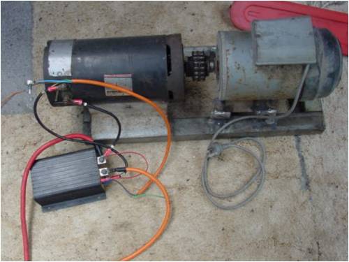
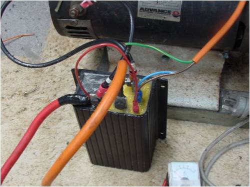
Note the hot glue holding the front of the power controller. Thats after I fixed it up, couldn't think what else to weather proof it with. The motor has NO capacitors in it at all. I run the dc motor up to about 1200 rpm, then turn on the ac motor. It pulls up to 1440, then wind the dc one up to however many amps of battery you wish to sacrifice... thats it. Replace dc motor with motor gearbox and blades, add black box from breezy or brew your own... (so you don't have to sit there and turn it on and off), and your done.... oh and a tower... and brakes.. ........oztules Village idiot...or... just another hack out of his depth |
||||
| The Back Shed's forum code is written, and hosted, in Australia. | © JAQ Software 2026 |
