
|
|
Forum Index : Microcontroller and PC projects : PicoMite/PicoMiteVGA V5.07.03 release candidates
| Author | Message | ||||
| Volhout Guru Joined: 05/03/2018 Location: NetherlandsPosts: 5999 |
Hi Geoff, Maybe Calli has a point. The [Quote] - Otherwise the cursor is placed on the last line edited. [/Quote] Is not behaviour in MMBasic for the picomite 5.070028 Cursor returns to top of file. Volhout PicomiteVGA PETSCII ROBOTS |
||||
| Volhout Guru Joined: 05/03/2018 Location: NetherlandsPosts: 5999 |
Hi Geoff, Maybe Calli has a point. The Is not behaviour in MMBasic for the picomite 5.070028 Cursor returns to top of file. Volhout PicomiteVGA PETSCII ROBOTS |
||||
| matherp Guru Joined: 11/12/2012 Location: United KingdomPosts: 11673 |
There is a bug. At the moment the cursor is placed at the top of the file UNLESS there is an error. I've found and fixed it ready for the next release |
||||
| wolfme Regular Member Joined: 26/10/2021 Location: GermanyPosts: 43 |
  |
||||
| matherp Guru Joined: 11/12/2012 Location: United KingdomPosts: 11673 |
Just playing  Grogster, fancy doing an adapter? 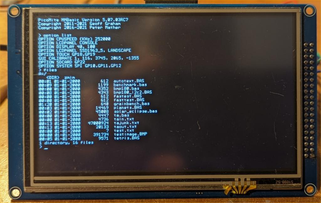 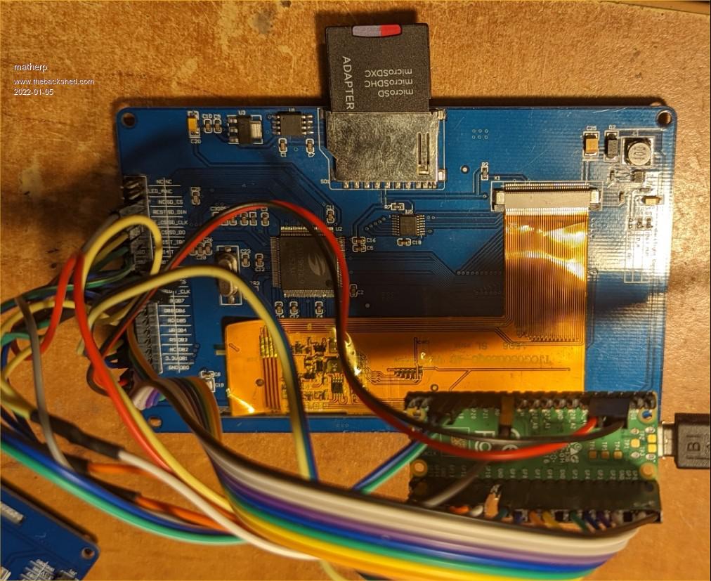 Edited 2022-01-05 03:54 by matherp |
||||
| thwill Guru Joined: 16/09/2019 Location: United KingdomPosts: 4380 |
What are we looking at, is this some sort of parallel display panel ? Tom MMBasic for Linux, Game*Mite, CMM2 Welcome Tape, Creaky old text adventures |
||||
| Mixtel90 Guru Joined: 05/10/2019 Location: United KingdomPosts: 8981 |
It is, yeah. I got one some time ago to go with my F4 (but still never got the two connected together as it involves some serious cross connecting when you put them back-to-back)! It's a pot-boiler project. Mick Zilog Inside! nascom.info for Nascom & Gemini Preliminary MMBasic docs & my PCB designs |
||||
mobluse Newbie Joined: 10/02/2013 Location: SwedenPosts: 24 |
PicoMiteVGA MMBasic Version 5.07.03RC7 Copyright 2011-2021 Geoff Graham Copyright 2016-2021 Peter Mather > option f1 "files"+chr$(13) > option list OPTION MONO VGA ON OPTION COLOURCODE ON OPTION SDCARD GP15, GP10, GP11, GP12 OPTION Audio GP18,GP19, on PWM channel 1 OPTION F5 files OPTION F6 files OPTION F7 files OPTION F8 files OPTION F9 files > files A:/ 00:38 01-01-2000 6991 aritm.bas 04:49 01-01-2000 6991 aritm2.bas 0 directories, 2 files > F1 does nothing, but is defined. Maker Pi Pico Rev1.2, DuinoMite-Mini, Raspberry Pi 0-4, iCE40HX8K, Arduino Uno, VM111, STK500, ZX81 |
||||
| Mixtel90 Guru Joined: 05/10/2019 Location: United KingdomPosts: 8981 |
AFAIK OPTION FNKey string$ only applies to F5 to F9. F1 to F4 are already allocated. See manual page 71. Mick Zilog Inside! nascom.info for Nascom & Gemini Preliminary MMBasic docs & my PCB designs |
||||
| Mixtel90 Guru Joined: 05/10/2019 Location: United KingdomPosts: 8981 |
@matherp That would be cool with a surface-mount PicoMite with a female header that just plugs straight onto the back of the display. :) Even nicer if there's still an I2C port to do some expansion with. Edited 2022-01-05 05:54 by Mixtel90 Mick Zilog Inside! nascom.info for Nascom & Gemini Preliminary MMBasic docs & my PCB designs |
||||
| fred777 Regular Member Joined: 01/07/2021 Location: United KingdomPosts: 99 |
Yippie SSD1963 on the Picomite... or not? PicoMite MMBasic Version 5.07.03RC7 > option LCDPANEL SSD1963_5, LANDSCAPE Error : Invalid display type  Aaaargh how can I get my hands on that version? Edited 2022-01-05 05:55 by fred777 |
||||
| thwill Guru Joined: 16/09/2019 Location: United KingdomPosts: 4380 |
Just experienced on the Maker Pi Pico at 133K what appears to be the same SD card problem I reported earlier using Mixtel90's backpack with the ILI9341 display/SD card. Does anyone know if the Maker Pi Pico board also has the offending resistors on the SD card lines? I can't find a schematic of the board but there are certainly a 4.7K and and two 3.3M resistors in the vicinity. Best wishes, Tom MMBasic for Linux, Game*Mite, CMM2 Welcome Tape, Creaky old text adventures |
||||
| Mixtel90 Guru Joined: 05/10/2019 Location: United KingdomPosts: 8981 |
According to the circuit I found it doesn't use resistors, Tom. Mick Zilog Inside! nascom.info for Nascom & Gemini Preliminary MMBasic docs & my PCB designs |
||||
| dMajo Newbie Joined: 18/05/2020 Location: ItalyPosts: 29 |
@matherp I am sorry for the misunderstandings probably due to my bad english as it is not my mother-language ... actually it is the third. I will try to explain the concepts better. Yes, the code is for a device. This code transforms the RP2040 in a sort of 2x FT232R or FT2232D/HL (dual-channel) FTDI USB slave to UART converter. ____________ _______ The aim is to allow the PC for eg.:_______ | HW COM1 |---| Dev.A | | | | | |_______| | PC | | PicoMite | | USB |--<CDC-VCOM1&2>-----| | _______ |_______| | HW COM2 |---| Dev.B | |____________| |_______| - to update the RP2040 FW, then download MMBasic app to it, then ask/activate the serial bridge through the console communication and (by changing the baudrate) manage FW updates of the downstream devices A and B - or configure Device A & B from the PC, where full command set is available while the MMBasic app implements only the limited/needed command set to deal with these devices in the field - or read the logs from downstream devices without MMBasic needing to process them - or simply experiment with the device during R&D - ... While, when enabled, the RP2040's COM2 will be constantly bridged to PC's CDC-VCOM2 (using its OPEN comspec$ BRI setting sfrom MMBasic app), for the COM1 instead: - when the PC sets eg 1800 (or 600 or it could be option defined) baudrate the CDC-VCOM1 traffic will go to the console (as now) and thus to the MMBasic app/interpreter - with any other PC's baudrate setting the traffic will be bridged to the RP2040's hardware COM1 port using comspec$ baudrate from MMBasic app (like the COM2 bridge). So the PC can eg.: - request a bridge-enable through the console - comunicate natively to both, the MMBasic app and the downstream device, using the baudrate as a switch/multiplexer between them - close the bridge by requesting it to the console through the defined baudrate setting - the MMBasic app will follow by opening and closing the COM-port with or without the BRI parameter. When in BRIn mode the MMBasic app will not be able to exchange data with the COMn peripheral. Any print#/input# statement will be ignored. I presume that open/close already empties the rx/tx buffers thus, since switching between BRI and normal mode requires OPEN/CLOSE commands, the MM app will not have a trashed buffer. The BRI option can't be used if the same port is already used with OPTION-SERIAL-CONSOLE. Now the PicoMite is also an easily programmable replacement for the FTDI USB2UART bridge similarly to the Tibbo's EM2000/1 and WM2000 that can do the same with 4/2 channels but over Ethernet/WiFi. Yes, the RP2040's UART supports only 8bit data + parity. The idea was to use the parity bit as 9th data bit by controlling its state after all the system's (?MMBasic) calls, to open the COMn channel, has been done. The slave's receiver is setup for 9bit while the slave's transmitter have 8bit configured, both without parity. Other COM params are the same as the master's ones. The RP2040 is the single-master of the bus. To do that you: - let the regular 'open com' happen when invoked, but without parity - set (directly into the UART's register UARTLCR_H) the SPS bit - ? if register UARTLCR_H bit FEN enabled disable it - then, when need to transmit, manage (interfere with) the transmit part: -- set, directly into UART's register UARTLCR_H, the PEN bit -- repeat the next steps for the required bytes to transmit (the tx buffer starts empty, N=1) --- analyze the N-pointed byte for how many 1 are in it --- verify that transmitter is empty (bit TXFE from UARTFR register) --- write (directly UART's register UARTLCR_H) the EPS bit accordingly to the desired value of the 9th bit you want to obtain --- pass the single byte to the transmitter for regular transmission --- repeat the above until end of transmission (N=N+1) -- when EOT in the UARTLCR_H register reset the PEN bit and ? re-enable FEN if you have disabled it Perhaps I should have written: Transmits 9bit data to serial communication port opened with file number @nbr and USR parity setting Syntax: PRINTWP #nbr,9thBitVal,expression [[,;]expression] Example: PRINTWP #5, 1, addr$ 'Transmit data with 9th bit set to 1 PRINTWP #5, 0, h$,d$,t$ 'Transmit data with 9th bit set to 0 That means choosing on the fly odd or even parity before the byte is delivered to the uart and then let it do its job. I was doing that already in early '90s between DOS (and even Win3.1/3.11) and 8051/2 slaves. But this, as said, is just a minor issue as to solve this on other platforms I have made a custom RS232<>RS485 with a "multi-uart" MCU which takes two bytes from one UART (up to 460kBps) and combines them in one 9bit on the other UART (up to 230 kBps) that could be appended also to the RP2040. Of course you can use also 8bit and define 7bit for data and use the 8th (MSB) bit as a switch between address and data ... or any other protocol. But the issue here is that the slaves have to be continuously listening and processing (even other's traffic) while with 9bit uarts they can do other things awaiting for their address to pass on the bus. At the end, if overcomplicated, this is irrelevant as there exists other solutions even if not cost-free, it was only to explain it better. ALLdataEE.com EDU Promos |
||||
Grogster Admin Group Joined: 31/12/2012 Location: New ZealandPosts: 10002 |
That works fine. Thanks! If I click the link in the forums, it won't for some reason, but copy the link to a new tab, "Paste and go" and it downloads fine. Perhaps just a quirk of the Opera browser I use. Smoke makes things work. When the smoke gets out, it stops! |
||||
| Grogster Admin Group Joined: 31/12/2012 Location: New ZealandPosts: 10002 |
Sure. Send me the schematic or post it here, and I can whip one up. Are there any pins left on the Pico after connecting a parallel LCD and touch? Smoke makes things work. When the smoke gets out, it stops! |
||||
| phil99 Guru Joined: 11/02/2018 Location: AustraliaPosts: 3325 |
"Are there any pins left on the Pico after connecting a parallel LCD and touch?" Looking at Peter's photo just a handful, If a keyboard and RTC are added it's about full. |
||||
| Mixtel90 Guru Joined: 05/10/2019 Location: United KingdomPosts: 8981 |
You only need 4 pins. Two for a keyboard, two for an I2c. An external I2C DAC would be fine if you want analogues, or a 28-pin Micromite for mixed IO. RTC can go on the same I2C bus. There are I2C keyboard designs around, in which case you only need two pins. :) Or use a "soft" on-screen keyboard, of course. Edited 2022-01-05 17:24 by Mixtel90 Mick Zilog Inside! nascom.info for Nascom & Gemini Preliminary MMBasic docs & my PCB designs |
||||
| matherp Guru Joined: 11/12/2012 Location: United KingdomPosts: 11673 |
https://geoffg.net/Downloads/picomite/PicoMite_Beta.zip PicoMite/PicoMiteVGA V5.07.03RC8 Enables F1 as a user programmable function key Fixes bug in cursor positioning in editor Fixes bug in error message when an invalid flash page is selected Implements support for SSD1963 parallel displays Check the video SSD1963_4, SSD1963_5, SSD1963_5A, SSD1963_7, SSD1963_7A, SSD1963_8 OPTION LCDPANEL SSD1963_n, orientation NB: SSD1963_8 also supports the 9" Eastrising display It is assumed the SSD1963 is configured for 1963_PWM backlight control in which case the BACKLIGHT command will work as expected Pin connections are as follows: DB0 pin 1:GP0 DB0 pin 2:GP1 DB0 pin 4:GP2 DB0 pin 5:GP3 DB0 pin 6:GP4 DB0 pin 7:GP5 DB0 pin 9:GP6 DB0 pin 10:GP7 RS pin 17:GP13 WR pin 19:GP14 RD pin 20:GP15 RESET pin 21:GP16 SSD displays support RGB666 and are much faster than SPI displays. The firmware includes full support for console mode. The downside is the number of pins used. A typical configuration could be: GP0-GP7 SSD1983 GP8-GP9 PS2 Keyboard GP10-GP12 SPI for touch and SDcard GP13-GP16 SSD1963 GP18-GP19 Touch CS and IRQ GP22 SD CS Leaving: GP17 I2C_SCL/COM1_RX/PWM0B GP20 I2C_SDA/COM2_TX/PWM2A GP21 I2C_SCL/COM2_RX/PWM2B GP26 ADC0/SPI2_CLK/I2C2_SDA/PWM5A GP27 ADC1/SPI2_OUT/I2C2_SCL/PWM5B GP28 ADC2/SPI2_IN/I2C_SDA/COM1_TX/PWM6A Notes for Grogster: The 4.3" display works fine using the Pico 3.3V supply The 7" display and bigger work using VUSB to provide the 5V assuming the USB supply is good enough The 5" display does not work reliably with the Pico 3.3V supply and would need an external 3.3V An adapter that supported both the normal 40-pin connection and the Eastrising variant would be great I haven't included defined pinout for RTC but would suggest GP20,21 I haven't included defined pinout for audio but would suggest GP26,GP27 but only as an option Keyboard connection would need a suitable level conversion ZVNL110A works perfectly as a cheap widely available MOSFET (RS 751-5278) Test Code Option explicit Option default none Dim x%(9),xd%(9) Dim y%(9),yd%(9) Dim integer i,c,f, xp, yp Dim float s CLS For i=0 To 9 Step 2 x%(i)=-(Sin(Rad(i*36))*200) y%(i)=-(Cos(Rad(i*36))*200) x%(i+1)=-(Sin(Rad((i+1)*36))*76) y%(i+1)=-(Cos(Rad((i+1)*36))*76) Next i Do c=Rnd()*255 + ((Rnd()* 255)<<8) + ((Rnd()* 255)<<16) f=Rnd()*255 + ((Rnd()* 255)<<8) + ((Rnd()* 255)<<16) xp=Rnd()*MM.HRes yp=Rnd()*MM.VRes s=Rnd() For i=0 To 9 xd%(i)=x%(i)*s+xp yd%(i)=y%(i)*s+yp Next i Polygon 10,xd%(), yd%(), c, f Loop Edited 2022-01-05 20:19 by matherp |
||||
| Grogster Admin Group Joined: 31/12/2012 Location: New ZealandPosts: 10002 |
This is what I have so far - just doing the major component placement at this stage:  PM down the bottom of the board to give easy access to its USB socket. ER connector at left side, standard 4-7" TFT connector at right(both on bottom) 3940 1A LDO 3v3 regulator to power both types of screen.(won't use the PM 3v3 output) Four-channel 5v/3v3 bi-directional level corrector(two channels for keyboard, the other two for COM1) Standard RTC module. Six-way PCB header for the six pins left over after all the tracks are laid. I plan to squeeze this layout a bit more horizontally, to make it 100x100. Once complete, I will certainly release all gerbers and drill data files etc. I think I will start a new thread for this board, so as to not hijack this one. Smoke makes things work. When the smoke gets out, it stops! |
||||
| The Back Shed's forum code is written, and hosted, in Australia. | © JAQ Software 2026 |
