
|
|
Forum Index : Microcontroller and PC projects : Pico Radar
| Author | Message | ||||
| Volhout Guru Joined: 05/03/2018 Location: NetherlandsPosts: 5994 |
Hi Gerald, When you post your test code, I will take a look to use framebuffers. I only have a ILI9341 with RP2350 combination, but it should be able to show what it takes. Which is actually quite simple. FRAMEBUFFER CREATE (creates framebuffer F, this is the background) FRAMEBUFFER LAYER (creates framebuffer L, layer on top) FRAMEBUFFER WRITE F write the grid to framebuffer F FRAMEBUFFER WRITE L DO read data from radar calculate X/Y coordinates on screen CIRCLE x,y,r,,,rgb(red),rgb(red) FRAMEBUFFER MERGE 0,b 'copies the merged data to LCD by second cpu, black -transparent LOOP Good luck Volhout Edited 2025-12-09 02:41 by Volhout PicomiteVGA PETSCII ROBOTS |
||||
| v.lenzer Senior Member Joined: 04/05/2024 Location: GermanyPosts: 124 |
Hi Volhout! I tried to buffer the graphic according to your instructions. I obviously did something wrong, because the graphic is only displayed for a moment. This is definitely happening right after the radar grid is generated. framebuffer create framebuffer layer arc 160,240,60,,285,75,rgb(green) arc 160,240,120,,285,75,rgb(green) arc 160,240,180,,298,62,rgb(green) arc 160,240,240,,318,42,rgb(green) line 0,0,160,240,,rgb(green) line 160,0,160,240,,rgb(green) line 320,0,160,240,,rgb(green) line 0,150,160,240,,rgb(green) line 320,150,160,240,,rgb(green) font 7:text 0,220,vers 'shows version in left bottom corner framebuffer write F framebuffer write L After that, I inserted the merge command into the subroutine that draws the dot. I commented out the CLS command in the program. Only one CLS command remains at the beginning of the program. sub draw_data circle x_draw, y_draw, 5, 1, 1, rgb(black), rgb(black) 'delete old position if param_arry(0,0) <> 0 then x_pos = param_arry(0,0)*h_fact 'scale to display y_pos = param_arry(0,1)*v_fact x_draw = x_0 + x_pos 'get display position y_draw = y_0 - y_pos circle x_draw, y_draw, 5, 1, 1, rgb(white), rgb(white) 'draw new position end if framebuffer merge 0,b end sub I was able to follow your instructions in the manual. However, it still doesn't work. Do you have any ideas? Edited 2025-12-09 04:07 by v.lenzer Best wishes! Joachim |
||||
| v.lenzer Senior Member Joined: 04/05/2024 Location: GermanyPosts: 124 |
I played around with "framebuffer" a bit. Now it works. It should look like this: framebuffer create framebuffer layer framebuffer write F arc 160,240,60,,285,75,rgb(green) arc 160,240,120,,285,75,rgb(green) arc 160,240,180,,298,62,rgb(green) arc 160,240,240,,318,42,rgb(green) line 0,0,160,240,,rgb(green) line 160,0,160,240,,rgb(green) line 320,0,160,240,,rgb(green) line 0,150,160,240,,rgb(green) line 320,150,160,240,,rgb(green) font 7:text 0,220,vers 'shows version in left bottom corner framebuffer write L No error messages appear! The RP2450 is running at 200000 kHz. The network lines are not overwritten. Edited 2025-12-09 04:34 by v.lenzer Best wishes! Joachim |
||||
| lizby Guru Joined: 17/05/2016 Location: United StatesPosts: 3812 |
How are people connecting these pins which are not .1", 2.54mm O/C like Dupont wires? PicoMite, Armmite F4, SensorKits, MMBasic Hardware, Games, etc. on FOTS |
||||
| Pluto Guru Joined: 09/06/2017 Location: FinlandPosts: 411 |
Among many other scrap wires, I had a cable coming probably from an old laptop display. It was a long connector with many, many twisted cable pairs. Cut off a suitable piece of the connector and 15cm of the (thin) cables. Attached dupont contacts to the cutted ends. There is still left over of the connector for several more radars.  Recycling as usual. Pluto |
||||
| ville56 Guru Joined: 08/06/2022 Location: AustriaPosts: 550 |
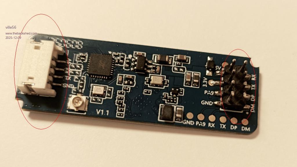
On my sensor (LD-2450) there are 2 connectors 1) 8-pin pin-header: From the manual it shows that the pin pitch is 2mm and the pins are 0.5 mm square. Mating connectors could be something like this: Connector if you are good in soldering, you can solder thin wires at the pins directly or at their pads on the pcb. 2) 4-pin inline housed connector: this is the one where pigtail cables are offered with the sensor. Both connectors offer the same signals (Vcc, GND, TX, RX), the 8-pin connector has some additional signals of, to me, unknown usage. Note: the RD-03 seems to miss out the 8-pin header, but I'm not sure as the manuals are not very precise (in every respect). 73 de OE1HGA, Gerald |
||||
| ville56 Guru Joined: 08/06/2022 Location: AustriaPosts: 550 |
 73 de OE1HGA, Gerald |
||||
| Volhout Guru Joined: 05/03/2018 Location: NetherlandsPosts: 5994 |
I was just starting to work on this, but saw you already solved it. Happy coding, Volhout PicomiteVGA PETSCII ROBOTS |
||||
palcal Guru Joined: 12/10/2011 Location: AustraliaPosts: 2039 |
Don't have a Pico2 but now running the CPU at 200000 I added the frmebuffer code but had problems, I had to add FRAMEBUFFER CLOSE F and FAMEBUFFER CLOSE L. Now it runs but I have the moving ball but no grid. "It is better to be ignorant and ask a stupid question than to be plain Stupid and not ask at all" |
||||
TassyJim Guru Joined: 07/08/2011 Location: AustraliaPosts: 6547 |
RD-03D 4pin connector is 1.25mm jst. The only other connection possibility is the test point pads which are 2.54mm spacing so if necessary, a standard header could be soldered on. This is what I did while waiting for some 1.25mm jst plugs. Jim VK7JH MMedit |
||||
| ville56 Guru Joined: 08/06/2022 Location: AustriaPosts: 550 |
- So the 4-pin connectors are the same on RD-03D and LD2450 - the test pads on the RD2450 do not have a Vcc pad ... 73 de OE1HGA, Gerald |
||||
| v.lenzer Senior Member Joined: 04/05/2024 Location: GermanyPosts: 124 |
@palcal: Maybe that helps. Radar_v.1.1.2.bas.zip Best wishes! Joachim |
||||
| palcal Guru Joined: 12/10/2011 Location: AustraliaPosts: 2039 |
@ v.lenzer, Loaded and ran that code but no go I get this when I have 'Trace On' .png) it gets stuck on line 594 Although it runs the code to display the grid nothing appears on the display. I have never used FRAMEBUFFER before, it's all new to me. Edited 2025-12-09 12:26 by palcal "It is better to be ignorant and ask a stupid question than to be plain Stupid and not ask at all" |
||||
| ville56 Guru Joined: 08/06/2022 Location: AustriaPosts: 550 |
Palcal, the code loops waiting for characters on the serial line in order to find the header of a datagram (synchronizing). Please check the lines 32 to 42 in the code for the setup of the serial line. You have to set the following 2 lines matching your setup: first define your pins for the serial line and assign com1 or com2. You can find more info in the MMbasic manual in appendix A (Serial Communications) setpin gp0,gp1,com1 next define the com, baudrate, buffersize, interrupt handler, interrupt threshold in a string const s_comspec = "com1:256000, 256, ser_int, 30" Looks like the sensor is not connected to the com that is used by Joachim, or you just rewire your com-port setup. Gerald 73 de OE1HGA, Gerald |
||||
| ville56 Guru Joined: 08/06/2022 Location: AustriaPosts: 550 |
Joachim, what is the MMbasic version you are running "Radar_v.1.1.2.bas"? Just tried in V6.01.00RC24 but got a crash .... [335] FRAMEBUFFER merge 0,b Error : Invalid character: ( Error: Invalid address - resetting 08:36:35 Port: COM22 removed Disconnected 08:36:36 Port: COM22 inserted Connected to COM22 at 115200 BTW: are you using PSRAM ? 73 de OE1HGA, Gerald |
||||
| Volhout Guru Joined: 05/03/2018 Location: NetherlandsPosts: 5994 |
Hi Gerald, The code Joachim is using is for a picomite with LCD screen attached. The FRAMEBUFFER MERGE 0,b is a command that works on LCD's only. See user manual. If your setup is different (i.e. VGA/HDMI) then the "FRAMEBUFFER MERGE" is not needed since the merging happens automatically in the PIO and second ARM in these platforms. You do not even have to assign a framebuffer F. FRAMEBUFFER LAYER (creates framebuffer L, layer on top) 'write the grid to layer N (the VGA screen). arc .... arc .... line ..... FRAMEBUFFER WRITE L DO 'read data from radar 'calculate X/Y coordinates on screen 'draw the dot FRAMEBUFFER WAIT 'optional to minimize screen flicker CLS : CIRCLE x,y,r,,,rgb(red),rgb(red) PAUSE 50 'whatever speed suits you LOOP This is how it works for VGA/HDMI Volhout Edited 2025-12-09 17:59 by Volhout PicomiteVGA PETSCII ROBOTS |
||||
| ville56 Guru Joined: 08/06/2022 Location: AustriaPosts: 550 |
Joachim, have removed your framebuffers again and now it uses BLIT display area copy. Before the ball is drawn, the display area of the ball is saved with BLIT READ and then the ball drawn. For the next display run, the area is restored with BLIT WRITE, the buffer is returned with BLIT CLOSE and the processing starts again. This works in the current implementation only for 1 ball as it uses only 1 buffer (#1). Its just for demonstration. But if you rewrite proc_data a bit ... there is idx pointing to the target (0 to 2). This can be used to have a seperate buffer for each target (idx+1) and pass the target info on to draw_data it should be easy. Had this running under RC24. Radar_v.1.1.2-blit.zip Gerald 73 de OE1HGA, Gerald |
||||
| v.lenzer Senior Member Joined: 04/05/2024 Location: GermanyPosts: 124 |
This is my setup: PicoMite MMBasic RP2040 Edition V6.00.03 OPTION SYSTEM SPI GP6,GP3,GP4 OPTION AUTORUN ON OPTION COLOURCODE ON OPTION CPUSPEED (KHz) 200000 OPTION LCDPANEL ILI9341, LANDSCAPE,GP7,GP2,GP5 OPTION GUI CONTROLS 10 I'm using a Zero with an RP2040. I haven't enabled PSRAM. My COM ports are GP0 and GP1. This corresponds to "config 1" in the source code. I defined the GUI controls because I want to offer a configuration menu. However, I haven't gotten that far yet. While experimenting, I accidentally added the line "framebuffer merge 0,b" twice in the `draw_data` subroutine (lines 335 and 346). While this doesn't cause any harm, it's unnecessary. One entry in line 346 is sufficient. After switching it on, the white dot might not appear immediately. Just wait a little while or wave your hands in front of the antenna. I have the Bluetooth antenna connected to my LP2540 and can operate the radar simultaneously with the Zero and the mobile app. Today I received the RD-03D. I'll try it with that as well. Perhaps there is a difference in sensitivity.  Best wishes! Joachim |
||||
| v.lenzer Senior Member Joined: 04/05/2024 Location: GermanyPosts: 124 |
Hi Gerald! The BLIT version works for me too. However, the lines over which the dot has passed become thinner. 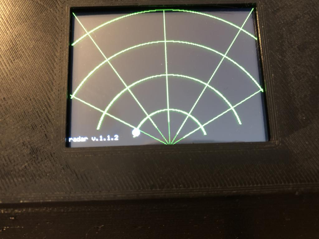 P.S: My BAUD-Rate ist 225000. You can change the baud-rate in the mobile app. Edited 2025-12-09 20:36 by v.lenzer Best wishes! Joachim |
||||
| ville56 Guru Joined: 08/06/2022 Location: AustriaPosts: 550 |
that is strange .... in fact I already found it couriouos that your gridlines were more than 1 pixel wide as you did not specify a width. This may have something to do with (line) drawing algorithm used in the firmware. btw, the fact that the dot does not always appear immediatela is because the sensor deliveres data with "no target" and that is suppressed in draw_data, statement if param_arry(idx,0) <> 0 then .... so you have to insert a target into the radar beam (hand) to get data which are worth to be displayed. You can look at the numerical data with no target just by pressing P and Z. 73 de OE1HGA, Gerald |
||||
| The Back Shed's forum code is written, and hosted, in Australia. | © JAQ Software 2026 |
