Notice. New forum software under development. It's going to miss a few functions and look a bit ugly for a while, but I'm working on it full time now as the old forum was too unstable. Couple days, all good. If you notice any issues, please contact me.
Mixtel90 Guru Joined: 05/10/2019 Location: United KingdomPosts: 9174
Posted: 03:57pm 16 Aug 2026
Copy link to clipboard
Print this post
It's still in the tweaking stage at the moment. Since that picture I've tidied up some traces that I wasn't happy with, moved the fuse to a cooler place, moved the Heartbeat link (which was colliding with the RTC), moved the VUSB light, tucked resistors under the hub to tidy things up and added a diode for the HDMI 5V feed.
It's coming along nicely but I've spotted something else I'd like to change a bit... :)Mick
@dddns Yes it is the Waveshare CoreBoard, ( step A2 )
JanVolk Guru Joined: 28/01/2023 Location: NetherlandsPosts: 414
Posted: 08:20pm 16 Aug 2026
Copy link to clipboard
Print this post
A simple test program to measure the core temperature and possibly apply cooling with a cooling plate or fan.
> save "core temperature.bas > run > F1=help F2=run F3=list F4=edit F5=clear F9=fm Ctrl+C=stop > OPTION CPUSPEED xxx000 (kHz) 48-348 MHz for RP2350B + PSRAM The room temperature :? 26.2 The core temperature of the PicoMite RP2350B is 47.2°C at 348 MHz at room 26.2°C The core temperature of the PicoMite RP2350B is 45.8°C at 348 MHz at room 26.2°C The core temperature of the PicoMite RP2350B is 47.2°C at 348 MHz at room 26.2°C > list Dim Float temp, Tin Print "> F1=help F2=run F3=list F4=edit F5=clear F9=fm Ctrl+C=stop" Print "> OPTION CPUSPEED xxx000 (kHz) 48-348 MHz for RP2350B + PSRAM" Input "The room temperature :";t Do Tin = Pin(temp) Print "The core temperature of the ";MM.DEVICE$;" is "; Print Str$(Tin,2,1);Chr$(176);"C at "; If Len(MM.Info(cpuspeed)) < 9 Then Print LEFT$(MM.Info(cpuspeed),2); Else Print LEFT$(MM.Info(cpuspeed),3); EndIf Print " MHz at room";t;Chr$(176);"C" Pause 6000 Loop >
Jan.
phil99 Guru Joined: 11/02/2018 Location: AustraliaPosts: 3407
Posted: 09:56pm 16 Aug 2026
Copy link to clipboard
Print this post
For an automatic approximation of Room Temperature you could replace
if you are using a DS3231 RTC. It reads the temperature every 64 seconds, holding the value in registers 17 & 18.
Edit. A bit shorter:-
RTC GetReg 17, T : RTC GetReg 18, T.25 : t = T + (T.25 >> 6) / 4
Edited 2026-08-17 10:22 by phil99
Mixtel90 Guru Joined: 05/10/2019 Location: United KingdomPosts: 9174
Posted: 09:45pm 17 Aug 2026
Copy link to clipboard
Print this post
Done more tidying up, most of the BOM (I need to add a pic or nine), changed the PROG socket to micro USB (trickier than it sounds), moved the power switch slightly and sorted out the silkscreen. Realized that the RTC was the wrong way up for easy installation and access so turned that over.
I'm not intending to do a manual as such for this, just a BOM (with some pics of the more awkward components) and a schematic. After that I'll probably release the gerbers for anyone who fancies fault finding an untested design. :) I'll probably order some boards too.Mick
JanVolk Guru Joined: 28/01/2023 Location: NetherlandsPosts: 414
Posted: 08:52pm 18 Aug 2026
Copy link to clipboard
Print this post
phil99,
Thanks for sharing. I’ve tested it with various PicoMite modules, and it works perfectly. Do keep in mind the type of DS3231 you are using, as this affects accuracy.
RTC GetReg 17, T : RTC GetReg 18, T.25 : t = T + (T.25 >> 6) / 4
Jan.
Mixtel90 Guru Joined: 05/10/2019 Location: United KingdomPosts: 9174
Posted: 06:54am 19 Aug 2026
Copy link to clipboard
Print this post
Yesterday was quite fruitful: Did the circuit diagram. I think that's all completed now. Did the bill of materials with pictures and a couple of notes done. GPIO port changed to include the system I2C pins, as on the later PC3 versions. Added PCB holes in case someone wants to screw the RTC down.
Ran the DRC checks again, and a lot of the point to point checks. Almost there now.Mick
This hasn't been built or tested at this stage, it's hot off the design table. If anyone wants to have a play they are welcome. I don't claim any originality for the original design, I've only done my best to translate it into modules. There's obviously no guarantee that it will work in an identical way to a PC3 (or even work at all for that matter!).Mick
matherp Guru Joined: 11/12/2012 Location: United KingdomPosts: 11974
Posted: 09:10am 19 Aug 2026
Copy link to clipboard
Print this post
Looks great Mick. I've done a cursory review of the schematic and it all looks OK but I can't check the module pinouts. One question: have you checked whether the pinout of the PGA2350 the same as the Waveshare version ? If it is it would give non-UK buyers another source.
Mixtel90 Guru Joined: 05/10/2019 Location: United KingdomPosts: 9174
Posted: 09:31am 19 Aug 2026
Copy link to clipboard
Print this post
It doesn't seem to be. I had a glance and there don't seem to be the same GND pins on the Waveshare. I will check further though.
Edit: No, they aren't pin compatible at all. Only the physical size is the same. :(
Mixtel90 Guru Joined: 05/10/2019 Location: United KingdomPosts: 9174
Posted: 09:44am 19 Aug 2026
Copy link to clipboard
Print this post
WARNING! Something might be odd with the gerbers. Some of the oval pads on the USB connectors seem to rotate for no apparent reason, even after I've reset them. I need to sort something out there.Mick
Mixtel90 Guru Joined: 05/10/2019 Location: United KingdomPosts: 9174
Posted: 10:18am 19 Aug 2026
Copy link to clipboard
Print this post
I *think* I can make a version of this board for the Waveshare CORE2350B. I'll have a look. There are a few pin changes but generally down the "controls" side.
I reloaded my SL6 file from the last save before I did the gerbers and it loaded ok. No pads had spun round.Mick
Mixtel90 Guru Joined: 05/10/2019 Location: United KingdomPosts: 9174
Posted: 12:16pm 19 Aug 2026
Copy link to clipboard
Print this post
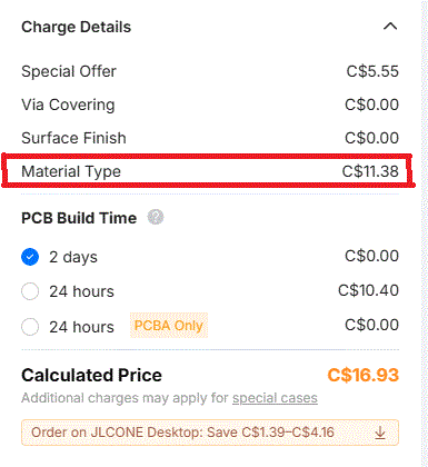
I'll be surprised if 0.01mm concerns them. I must confess that SL6 measures this at 100.008mm, but I've already had several boards made using this outline already without incurring extra charges.Mick
dddns Guru Joined: 20/09/2024 Location: GermanyPosts: 916
Posted: 01:38pm 19 Aug 2026
Copy link to clipboard
Print this post
After all basic components work, I have no success getting the Pimoroni RM2 Breakout board to work. I've tried it with the latest WebMite firmware and get:
WebMite MMBasic RP2350B Edition V6.03.01 Copyright 2011-2026 Geoff Graham Copyright 2016-2026 Peter Mather
I have tried it with WebMiteRP2040 and an all pinout RP2040 clone. It doesn't say hdr mismatch but immediately fails with initialization.
Edit: if I unplug the RM2 module on my PC3 clone the output is:
WebMite MMBasic RP2350B Edition V6.03.01 Copyright 2011-2026 Geoff Graham Copyright 2016-2026 Peter Mather
Total of 6 Mbytes PSRAM available [CYW43] Failed to start CYW43 [CYW43] Failed to start CYW43
repeated forever Edited 2026-08-19 23:56 by dddns
matherp Guru Joined: 11/12/2012 Location: United KingdomPosts: 11974
Posted: 02:01pm 19 Aug 2026
Copy link to clipboard
Print this post
I would suspect a duff board with either a short or dry joint where the rm2 mounts on the carrier. Assuming you have followed the wiring precisely as per the Pimoroni website there is nothing else obvious that could be the cause (unless the rm2 module itself is duff or the resistor values on the carrier are wrong)
Page 4 of 6
Print this page
The Back Shed's forum code is written, and hosted, in Australia.

 Notice. New forum software under development. It's going to miss a few functions and look a bit ugly for a while, but I'm working on it full time now as the old forum was too unstable. Couple days, all good. If you notice any issues, please contact me.


 Print this post