
|
|
Forum Index : Windmills : The MPPT Project.
| Author | Message | ||||
Highlander Senior Member Joined: 03/10/2006 Location: AustraliaPosts: 266 |
MMPT looks a bit too hard for me. 
Ross, take it easy mate. Your skill is quite clear, I've seen the pics of your setup. 
Dennis your knowledge is also to be envied, countless hours of testing has given you an edge. Can you start a thread on your cap conversion? My attempt at using caps was a failure here Central Victorian highlands |
||||
| GWatPE Senior Member Joined: 01/09/2006 Location: AustraliaPosts: 2127 |
Hi all, The discussion had stalled for a bit and has now some direction. Firstly, Gizmo, I almost completely agree with your interpretations about MPPTing vs power increasing. You cannot get something for nothing. Remembering that most testing is done with constant rpm, make change and compare result. I am aware that F&PwithPVC has the luxury of testing with 2 mills at the one site and making changes to one and not the other and visually comparing outcomes in the same air. This demonstrates that if a power output gain occurs following a change that the alteration has allowed the blade to extract more energy from the same wind, and the change has made the total system more efficient. My experience has been, match the mill maximum output for the maximum wind the mill is expected to operate at safely, given the number and length of blades, tower strength, furling, system battery voltage. May be other constraints as well. The blade rpm should be 400-500 so noise does not become a problem. The 80SP in star would fill that requirement. The blade length and number should give approx 400W at the 400rpm, when directly connected to the battery. This combination has to provide sufficient torque to start the mill in say 5-6knots. the power available at the bottom end is < 10W. 80SP star produces 9V OC at around 100rpm. My cct design would enable battery charging from the 80SP, when voltage output rose above 9V. A little positive feedback hysterysis in the cut in voltage reduces start up oscillations. I have attached some photos. I have described how the cct works in previous posts. pic 1...mill in operate mode, red light ON means caution when working on mill. 
pic 2...mill in brake mode. green light ON means safe to work on mill. 
pic 3...cct includes control 12v supply, modulator and fixed low end current shunt. 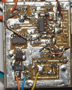
pic 4...cct includes swithing transistor and steering diodes and bypass caps. 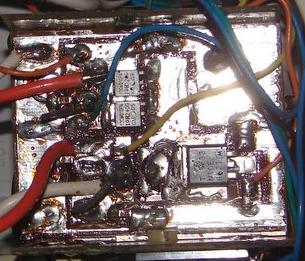
pic 5...topside of pic3 showing input and output main filter caps and pot core inductor. 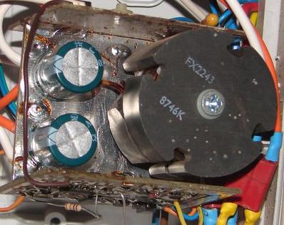
pic 6...cct includes voltage controlled shunt and mill overvoltage detection and protection cct. 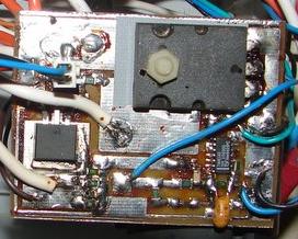
I think you can see that the construction should not be breadboarded. each of the cct boards require screening with an earth plane to reduce coupling that causes detrimental feedback. I may have been a little lucky with this design. I may be able to help out in the micro control dept. I am not familiar with the picaxe micro. Does it require programming software. I am very familiar with the stampII system. The code posted above is very similar to the BS2 basic interpreter code. I have thought about the problem from a software aspect. All that has to be measured is the voltage across the shunt and the mill voltage. If the boost cct is used, then almost the full output of the micro PWM could be used. I think that all combinations of ideas will help, as the less work the electronics have to do, then the simpler and cheaper they should become. I totally agree with the parallel tuned cct with caps approach as introduced by Dennis. This helps by reducing the demands on the electronics. I do not believe that current electronic components allow for one cct to be used for all types of F&P windings. The data to date suggests that for 24V system that 80SP star would be the best stator to match the voltage. The blade arrangement is where more variables come into play and these will be location dependent as well. I hope we don't lose too much sight of the overall objective. cheers, Gordon. become more energy aware |
||||
| RonS Newbie Joined: 19/06/2007 Location: AustraliaPosts: 18 |
Hi Warpspeed. Have you worked with magnetic amplifiers? They are nice and robust (being based on transformer technology for those unfamiliar with them)but I wonder if the variable frequency might cause some grief? What are your thoughts? (The military love these things because they are essentially immune to radiation and EMP overloads. They are a teensy bit slow, in some respects,though). regards, Ron Avoid strong drink. It makes you shoot at tax collectors ...and miss. |
||||
| GWatPE Senior Member Joined: 01/09/2006 Location: AustraliaPosts: 2127 |
Gizmo, I have just ordered some pic axe007M-sm devices. Should have them by next week. I will prototype test cct to see if software response time is adequate to use as MPPT controller. A working mill cct will still be a way off yet. Was a bit of bad luck with your mill. Looks as though the mill did not furl and the blade load was too much. You may get away with uPVC cement. I would drill some pinning holes, or cut some slots across the break and glue in some PVC and then sand all back and repaint. This will reduce blade imbalance problem. has any one calculated wind energy per m^2 blade energy at increasing wind velocity? cheers, Gordon. become more energy aware |
||||
| RonS Newbie Joined: 19/06/2007 Location: AustraliaPosts: 18 |
Hi Gordon. I have a handy little nomograph for wind velocity versus wind pressure, if that would be any use. It is in Imperial units, however. Regards, RonS Avoid strong drink. It makes you shoot at tax collectors ...and miss. |
||||
| GWatPE Senior Member Joined: 01/09/2006 Location: AustraliaPosts: 2127 |
Hi RonS, A table might be easier to post, but a scanned version would be OK. A prelim Pic AXE007m code follows ' this relies on a voltage controlled shunt sensor in the generator output negative ' system shuts down generator if generator voltage exceeds 29.5V ' system will not start if input3 is LOW, has on board pullup on it ' system senses if load is disconnected ' requires separate bridge rectifier cct ' The idea is to modulate and keep the value of Shunt sense voltage at 100, this is about 2.5 V ' pin 6, ADC1 is generator voltage ' pin 3, ADC4 is current shunt sense voltage ' pin 5, PWM2 is mosfet drive output ' pin 7, OUT0 is shutdown control output ' pin 3, IN3 is load voltage sensing and manual, system shutdown control input Symbol Shunt = W0 Symbol GenVolts = W1 Symbol PulseWidth = b7 Start: pwmout 2, 62, 0 Main: if pin3 = 0 then ShutDownAll ' either no output load or switched OFF readadc10 1, GenVolts 'Read a generator voltage value readadc10 4, Shunt 'Read a shunt voltage value if GenVolts < 200 then ShutDown 'Not rotating fast enough yet, wait a while if GenVolts > 800 then ShutDownAll 'Generator OverVoltage shutdown if Shunt = 500 then goto main 'system steady, leave alone if Shunt < 450 then RealFastUp if Shunt > 550 then RealFastDown if Shunt < 480 then FastUp if Shunt > 520 then FastDown if Shunt < 500 then Up 'Load generator a bit more if Shunt > 500 then Down 'Unload generator a bit goto main ' not really needed as all tests done above ShutDown: pwmout 2, 62, 0 PulseWidth = 100 'Set a mid range pulsewidth when control resumes goto Main ShutDownAll: pwmout 2, 62, 0 PulseWidth = 100 'Set a mid range pulsewidth when control resumes" high 0 sleep 10 'Wait for about 20 seconds low 0 goto Main RealFastUp: PulseWidth = PulseWidth + 5 gosub OutputPWM goto Main RealFastDown: PulseWidth = PulseWidth - 5 gosub OutputPWM Goto Main FastUp: PulseWidth = PulseWidth + 2 gosub UpdatePWM goto Main FastDown: PulseWidth = PulseWidth - 2 gosub OutputPWM Goto Main Up: PulseWidth = PulseWidth + 1 gosub OutputPWM goto Main Down: PulseWidth = PulseWidth - 1 'if PulseWidth < 1 then PulseWidthOne gosub OutputPWM Goto Main OutputPWM: pwmout 2, 62, PulseWidth PulseWidth=PulseWidth min 5 PulseWidth=PulseWidth max 200 return Runs properly on the simulator. This code will only properly work using a voltage controlled shunt. I hope to make the test cct next week. cheers, Gordon. become more energy aware |
||||
Gill Senior Member Joined: 11/11/2006 Location: AustraliaPosts: 669 |
G'day Gordon, Just a little problem in transferring the programme to the forum. Seems you missed a bit as "gosub UpdatePWM" does not syntax check. UpdatePWM is missing???? And for us dummies, what is cct???? Following with great interest and looking forward to a new BIG BOY TOY ADD-ON if all goes well.  was working fine... til the smoke got out. Cheers Gill _Cairns, FNQ |
||||
| GWatPE Senior Member Joined: 01/09/2006 Location: AustraliaPosts: 2127 |
sorry gill, one rename slipped through. The code will be of no use without the cct layout as well, so I wasn't too careful. I did not make any comment on gizmo's pmwout on the post above. I guess gizmo's code example above must have produced a myriad of syntax errors and was not meant to work either! I suppose as this was a 20 minute effort, and with me having never programmed this chip before, that I haven't done too bad a job. a cct is just shorthand for printed circuit board. This may all still be a pointless exercise, as all that so far has been achieved is replacing one IC with another IC. All the important bits cannot be put in software. I still have my concerns with the clunky PWM digital output, compared to an analogue PWM like a 494 or 3524. I have other plans for the picaxe if the response is too slow. enough for now, Gordon. become more energy aware |
||||
| vasi Guru Joined: 23/03/2007 Location: RomaniaPosts: 1697 |
[quote=GWatPE]I am not familiar with the picaxe micro. Does it require programming software. I am very familiar with the stampII system. [/quote] Is a very detailed pseudocode and mean one thing: GWatPE is ready to handle PICAXE chips. Hobbit name: Togo Toadfoot of Frogmorton Elvish name: Mablung Miriel Beyound Arduino Lang |
||||
herbnz Senior Member Joined: 18/02/2007 Location: New ZealandPosts: 258 |
Hi good see topic back on track. I personally will carry on working on a switch mode cct that will bring a high voltage down computers use 300 volts down to 5 volts. Instead of a simple inductor they use a secondary winding. I think there is a lot to be gained out of FP on high volts reducing the ampere turns Also many situations where distance is involved. Control wise tho any one into neural logic ? Herb |
||||
| GWatPE Senior Member Joined: 01/09/2006 Location: AustraliaPosts: 2127 |
Hi HerbNZ, Switchmode PS have been around a long time in the PC field. Most PC's have 300-500W PS. Most require a fan. I know of a handful that don't, but these passive systems have very large convectively cooled heatsinks. I have 24V switchmode battery chargers and measured efficiency is only 80%. PC PS is lower efficiency still. These all use secondary windings for mains isolation. I am not sure if users would agree to lose 20% of mill power instead of rewiring. and losing < 5%. your thoughts. cheers, Gordon. become more energy aware |
||||
| herbnz Senior Member Joined: 18/02/2007 Location: New ZealandPosts: 258 |
Hi Gordon You are more than likely right I can not get eff but until I exhaust all possibilities I will try. Nothing wrong in going down the wrong path sometimes suprises at the end learning along the way is the thing. Inverters using switching have acheived 90+% My interest in higher volts is not i confess only related to windmills i would like to use higher speeds on FP smart drives . also eff on smart drives is not as high as people believe there is room to gain. Herb |
||||
| GWatPE Senior Member Joined: 01/09/2006 Location: AustraliaPosts: 2127 |
Hi all, Have revised the code and made a simple test cct. the picaxe micro code posted produced glitches in PWM output. too many decisions had to be made. I have simplified the code and with only 11 lines of code within the control loop I have a glitch free output. The full span response is quite slow, about 2 seconds. real life testing will see if it can meet the task. Oscillations may occur as the cct responds to the changing wind. In comparison the analogue version can respond in < 2ms. This is a pic of the test cct. This includes micro, regulated power supply, 6V-35V in, and on board serial programming port. the mill cut in and overvoltage can be real time simulated as well as the measured current and a visual indication of the output PWM signal. The picaxe PC simulator and debug commands cannot respond fast enough. 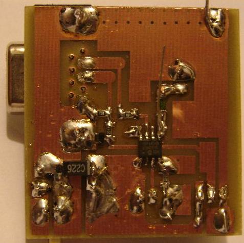
If all goes well I will publish experimental test data from an F&P mill. cheers for now, Gordon. become more energy aware |
||||
Megawatt Man Senior Member Joined: 03/05/2006 Location: AustraliaPosts: 119 |
Hello RossW, if you are still reading this forum, please recognise that only one member has made an unfortunate response and that perhaps the other 10 (I didn't count) contributors, like myself have valued your considered input. Please ride with the punches, we're only here once and community contributions from our specialities are the most valuable things we have to offer. Megawatt Man |
||||
| GWatPE Senior Member Joined: 01/09/2006 Location: AustraliaPosts: 2127 |
Hi RossW, I have a similar sentiment to Megawatt Man, This post is for discussion on a MPPT system. I am working within the spirit of this thread. It is possible that other opinions posted here do increase the power output of a mill and allow a particular mill to capture more energy. This does not mean that this system is a MPPT. We could easily increase the maximum power by reducing the tail furling and push the mill harder in stronger wind. We should consider the thread is for all to see and negative posts can be taken personally. We should be objective when figures are posted. MPPT is getting more power from the available wind by keeping the rotor at the most efficient rpm at that wind speed(wind energy) My MPPT only performs its function in the bottom 60% of the wind energy spectrum. At the top end the mechanical overload and then electronic overload systems are working to prevent overload damage, so there is no point in trying to MPPtrack. I have asked if anyone has a graph of wind energy v wind speed per m^2 I have used, energy = 1/2 air density x blade area x air velocity ^3 [consistant units have to be observed] The graph would be very useful to all. I hope that I am not working alone, rebuilding my electronic version of a MPPT. On a previous post, commercial MPPT were mentioned. I think AERL has a cct that matches a wind generator to a battery load. I do not think it is a MPPT though. Does anyone have a brand name? cheers, Gordon. become more energy aware |
||||
| domwild Guru Joined: 16/12/2005 Location: AustraliaPosts: 873 |
Friends, Thanks must go to Glenn for warming up this "holy grail" question. I am disappointed at the many unrelated suggestions, such as forgetting all about MPPT as capacitors give you more power, etc. Let's stick to Glenn's structure and let's reiterate what Glenn has already solved and what needs still to be solved: Glenn has already achieved the following so let's not try to reinvent the wheel. Picaxe hardware and software for the following: Wind speed RPM Voltage into battery Amps into battery via resistor voltage drop, Allegro hall sensor solution is given in jimovonz's solution Dump load switching Suggested code for PWM Glenn has already tried to structure the solution by suggesting blocks, i.e., a solution of a huge problem by top-wise decomposition into "blocks". The block crying out for a solution are the buck converter. Let's stick to buck and let's not muddy the waters with suggesting boost as we are interested in higher power only - "keep it simple". One buck converter solution + wind mill I have come across is inefficient and is listed as a student project for India (Gujarat) by "American Engineers", I believe. If there is interest, then I can dig up the web page. This buck solution also uses caps as has been suggested by PVC man Latham. Another PWM solution I have come across is a totem pole schematic on Fieldlines; I believe this forum member is driving the dump load via PWM. Once again, if this solution is not known I can dig up the web page if it is useful for Glenn's MPPT project. Please do not muddy the waters and get off-topic. Regards, Taxation as a means of achieving prosperity is like a man standing inside a bucket trying to lift himself up. Winston Churchill |
||||
| herbnz Senior Member Joined: 18/02/2007 Location: New ZealandPosts: 258 |
Hi All I believe the topic is getting bogged down in control technics before we have something to control. Gordons ideas of boost are very valid but myself I will investigate getting eff out of voltage reducing requlators I am told computers etc can not get eff but I see many still using transistors commercial development is not always after eff.I would like to built up a unit using like push pull cct into a transformer a transformer can then help reduce voltage. The clever chips around nowdays appear to offer simple interfacing. |
||||
| Gill Senior Member Joined: 11/11/2006 Location: AustraliaPosts: 669 |
Gordon, The commercial wind MPPT controllers below are way to expensive. http://www.solacity.com/Scirocco.htm http://www.leonics.co.th/support/brochure/2_gwt300_en.pdf Whilst I understood there to be MPPT devices available for wind generators, I cannot find any of what I was expecting(stand alone type). I see all the wind ones quoting MPPT are grid interactive and are incorporated into a system usually including an inverter and the grid tie stuff. This story http://www.otherpower.com/guemes07.shtml tells how the Outback techs modified one of their MX60 solar MPPT controllers for wind use, but it is only mentioned and no details are given. I always thought the MX60 was one but that is not so. So sorry Gordon I can't produce a product number or a manufacturer for a stand alone device. Perhaps someone else has the info? If indeed they are so rare, then they are indeed difficult to design. Perhaps we should be a bit more flexible about software control because even a hardware one that works is still good? was working fine... til the smoke got out. Cheers Gill _Cairns, FNQ |
||||
| GWatPE Senior Member Joined: 01/09/2006 Location: AustraliaPosts: 2127 |
Thanks Gill, I did a lot of checking before I made my MPPT cct. The grid interactive one I know of is called a WindyBoy by SMA. As I understand, this requires a digital model of the wind generator output curve. Control is similar to automotive engine management. This unit still only loads according to the output voltage of the mill. on other business, The picaxe code works on the test unit. Will now design new board and incorporate micro with current sensing and Mosfet drive and Shutdown components. Hi Gizmo, The 256 byte program and 14 byte variable allocation of a picaxe-07M severely limit number crunching and decision making. Hi domwild, Please be aware that picaxe chip, similar to those used by Gizmo were chosen as they are cheap. I think that Gizmo will confirm that his code pretty well fully used the picaxe micro. Do you suggest any way of interfacing the modules. We need to measure analogue and digital signals, and then combine these with other analogue and digital signals. How do you suggest Digital numeric transfer of information between modules? I have just finished another application of the picaxe micro. I measured 2 analogue and 2 digital inputs and had a single digital output. Some code for upper and lower bounds on the analogue inputs and some digital timing delays. Even using byte variables and minimal word variables, I used all the variable space and 80% of the program space. This project has to use minimum power and be stand alone. It cannot require a PC for operation. I think we all need to understand that commercial units as mentioned above cost thousands of dollars per KW. None of us have a wind tunnel to produce a power output profile for our mill so we cannot really use a commercial unit either. cheers for now, Gordon. become more energy aware |
||||
Cliff Newbie Joined: 23/07/2006 Location: AustraliaPosts: 4 |
Hi all A few post ago GWatPE mentioned that he had some problems with the PicAxe code similar to Gizmo. The problem is the use of the 'SLEEP' command it will turn off the pwm output, 'PAUSE' will work and does not stop the drive to the fet. Regards Cliff |
||||
| The Back Shed's forum code is written, and hosted, in Australia. | © JAQ Software 2026 |
