
|
|
Forum Index : Electronics : Good money after bad - Solar upgrade time
| Author | Message | ||||
| oreo Senior Member Joined: 11/12/2020 Location: CanadaPosts: 133 |
Well, from January to November the hydro rates have gone up about 6% here. There was no price increase in the cost per KWH, however the electricity rebate was reduced from 19.3% to 13.1%. No big deal. However the new rates that just started in November are considerably more expensive. The rate plan I am currently on has increases ranging from 28.7% to 39.3% (different increases for different usage times). I suspect that they will initially employ a much higher rebate to reduce the number of complaints and then just reduce the rebate over time. Of course this just gives me more reason to stop being so lazy and finish building up the second transformer so I can move more stuff over to the inverter. The items I would like to move over are A/C, stove and dryer. I have all the materials for the inverter, but will need some items to beef up the battery charger. Note: After a little googling, I see that the rebate has gone from 13.1% to 23.5%, which makes the effective increase from 16% to 22%. I guess the party is over.  Edited 2025-11-08 13:44 by oreo Greg |
||||
| KeepIS Guru Joined: 13/10/2014 Location: AustraliaPosts: 2177 |
Love the photo, we will be facing a similar problem here before long. I can report that I'm still 100% off grid with total disregard to the power we are using, dual ovens, Hotplates, washer dryer, big hot water system, 3 aircons, workshop, and on it goes, through winter and a few days with low solar and two days with almost none, lowest battery level was 38% after two days of no solar. I'm still amazed, the Inverter has seen 14kW at times, and often runs with constant cycling between 8kW to 10kW for an hour or so each day. It runs virtually cold, highest FET heatsink temps were 38° and the Toriods have never gone above 42°, which basically feels like a slight warmth to the touch on a 37°c day . Edited 2025-11-08 14:00 by KeepIS NANO:Inverter V 8.2ks - Linux AvrDude GUI script V4.1 |
||||
| oreo Senior Member Joined: 11/12/2020 Location: CanadaPosts: 133 |
I hope everyone had a wonderful Christmas and are set for an eventful 2026! I did a bit of work in December on the system, mainly because I got my hands on a few more batteries on the really cheap. I was not planning on expanding the battery, but you know how these things go. So right now I have 2 batteries, one with 26 internal 36v packs and one with 20 internal 36v packs. On top of the smaller battery, I have the MPPT and battery charger mounted. So the plan was to relocate these 2 items, so I could add another 6 packs to the 20pack battery. Moving the MPPT was fairly easy, as I just moved it to the wall. 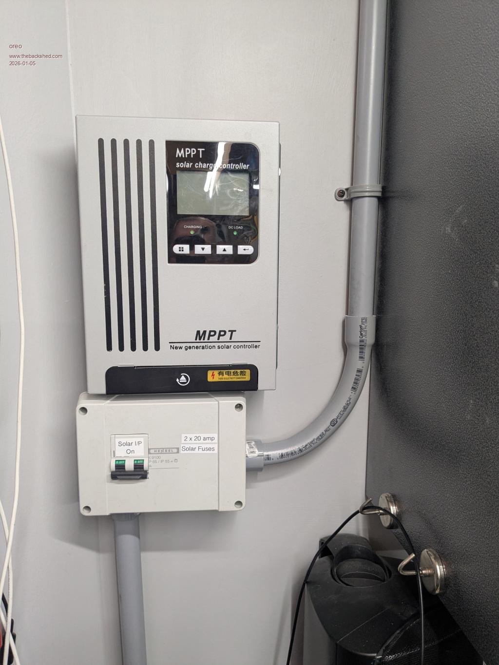 Rather than just move the charger, I decided to upgrade it. Theoretically, my previous charger should have been able to charge at 25amps (~1950w), however it used 2 12.5amp 54v power supplies in parallel, and each supply tended to hog all the current, and then shut down. I jury rigged it by putting some resistance in series with each power supply, but every once and a while they did not play nicely. This led me to reduce the current to about 20amps. On top of that, the efficiency of the setup was not ideal, due to this resistance and also the fact that I had a diode array in series with the supply to stop back flow of current. This array had a drop of about .68v across it. So I ended up replacing the 2 12.5a 54v power supplies with 5 12v power supplies. (2 are SUPERMICRO PWS-1K02A-1R and 3 are HP HSTNS-PL29) I also purchased another Mean Well HEP series 24v supply, with adjustable current limit, however this was a 13.3 amp unit to put in parallel with the 25amp unit I have. In all, this should theoretically yield close to 3kw of charging power. I replaced the series diode bank with more V40100C diode pairs to drop the forward voltage to .40v. One of the problems with using these cheap 12v power supplies, is that as supplied each connects the -ve rail to the ground pin on the AC and they have many capacitors between the -ve terminal, and the live AC for noise suppression. When you string a bunch of these power supplies in series, even with their AC ground pins unconnected, there is quite alot of AC being injected into the dc by all those capacitors in the group of supples. So I opened up the supplies and removed the capacitors. 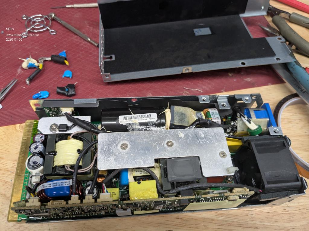 Some of these supplies are 96% efficient, and I see they are using FET's to reduce the forward drop on the AC side bridge rectifier. Very cool. 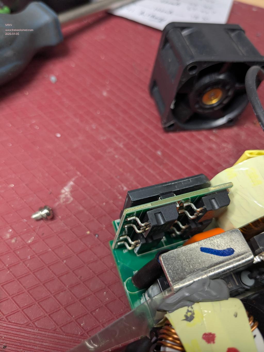 Anyway, I mounted these supplies in some boxes I got off marketplace, and mounted them on the wall. I still have work to do here, as the 13.3amp supply has not arrived, and I want to add more functionality to the charger. 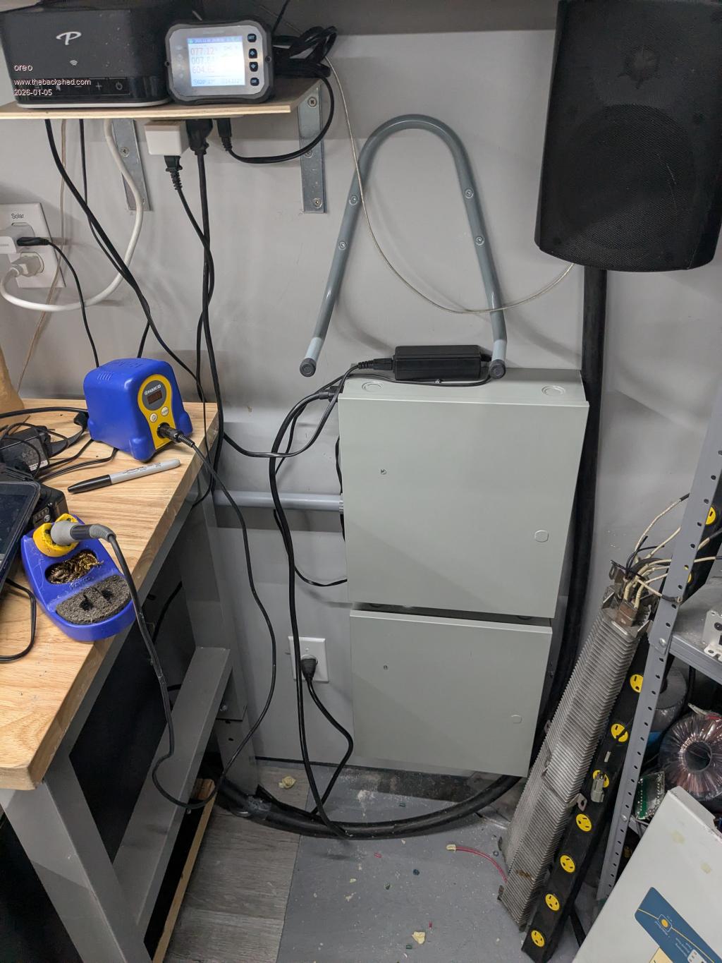 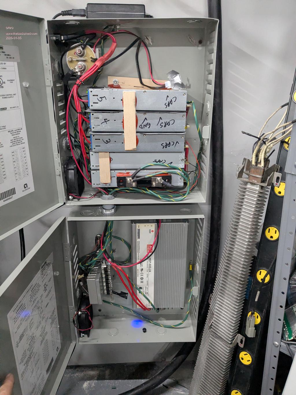 Greg |
||||
| oreo Senior Member Joined: 11/12/2020 Location: CanadaPosts: 133 |
So now the top of the battery was clear, however I had added items onto the battery in a hodge podge manner and had wires entering the battery on 3 sides. So I took to opportunity to improve this by both increasing wire sizes and moving all entry into the box to the rear of the battery on a separate panel. I also changed out the couloumeter to a Junctek KM110F which has wireless, so I can view the battery condition anywhere. This is what it looks like now. 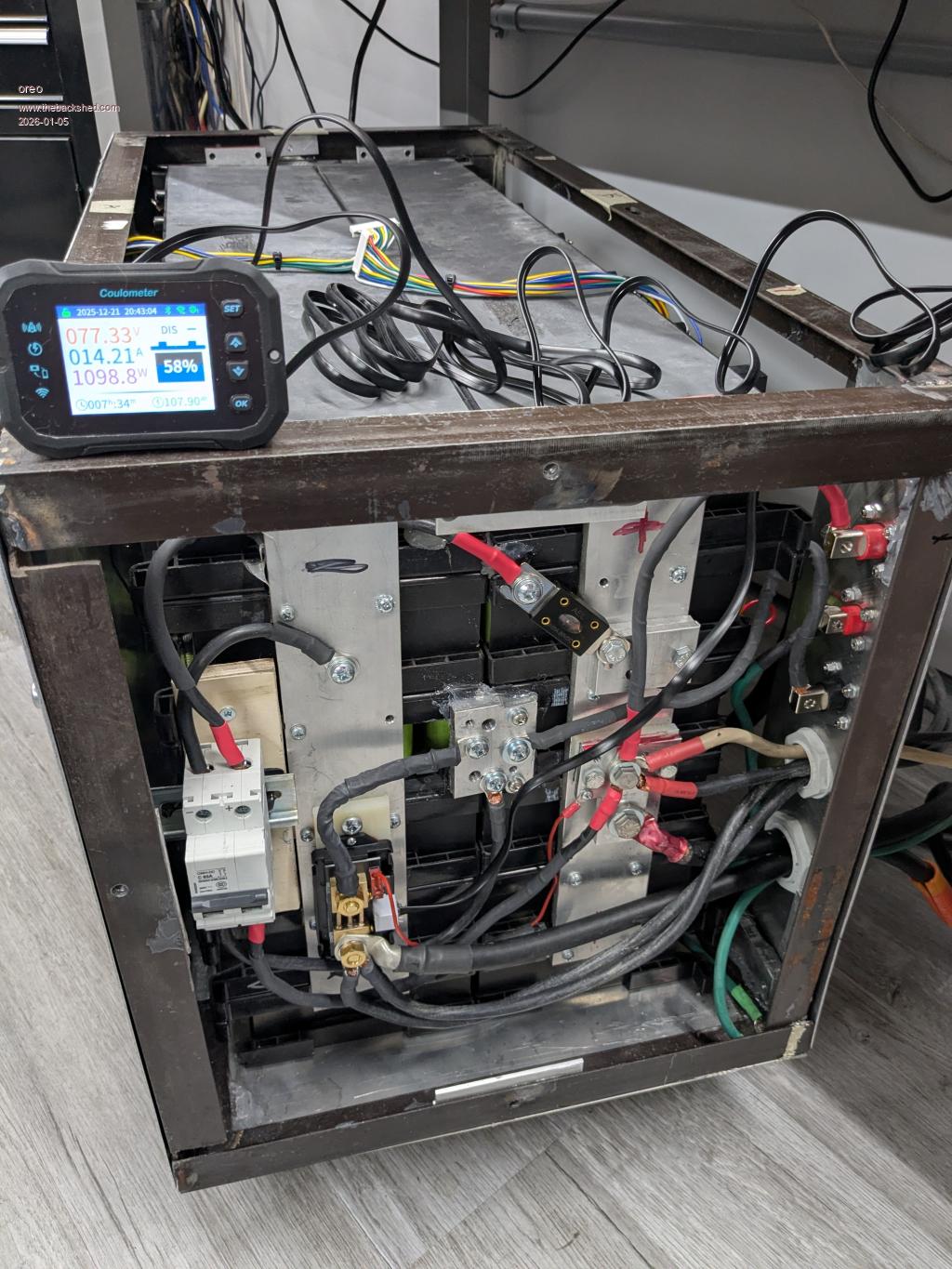 Everything seemed to be working well, and I was getting ready to install 6 more battery packs on the top of my battery, when the inverter popped. I was in the basement at the time, and there was no change in noise level or anything, just the breakers on the batteries and inverter tripped. It was in the middle of the day, so there would not have been much of a load on the inverter. In testing I can only find that Q5-Q8 and Q13-Q16 have failed. The little power supplies and driver transistors are ok. I am thinking of using my back up board as replacement rather than fixing this one.. I can't see any other issues at this point. Thoughts on what else to check? 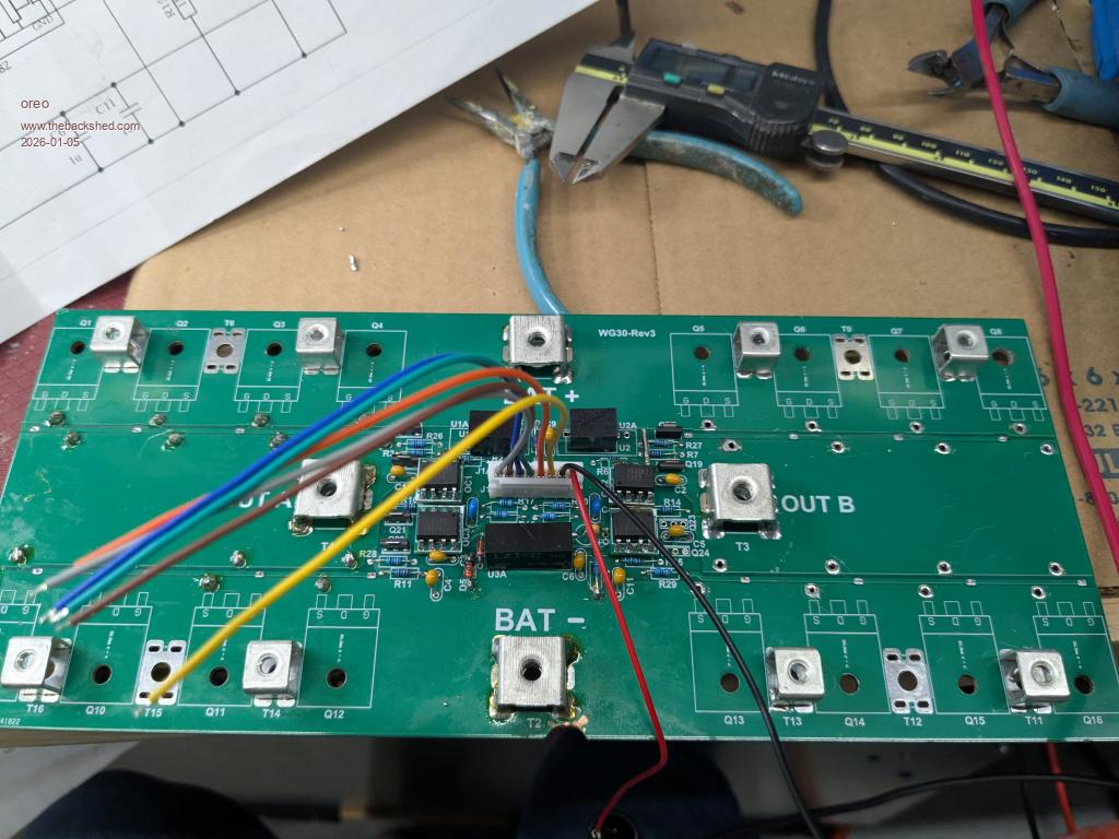 thanks Greg |
||||
| KeepIS Guru Joined: 13/10/2014 Location: AustraliaPosts: 2177 |
Replace the gate resistors, they can be compromised, I had that issue after the old changeover ATS I was using arched Mains AC to Inverter AC and took out a few FETs. I hope you can find the cause as this really should not happen with this inverter unless something like a flaky component failure or other external device fault. NANO:Inverter V 8.2ks - Linux AvrDude GUI script V4.1 |
||||
| wiseguy Guru Joined: 21/06/2018 Location: AustraliaPosts: 1296 |
I have re-read the last few pages of your thread and now I have a question, what choke cores are you using now? The page link you posted for amorphous nanocrystalline cores, I did not follow the link at the time as I assumed that you had found suitable similar cores. After taking a closer look, the ferrite in my opinion is totally unsuitable for this type of inverter. It is usually used for transformers and EMI filters which require no energy storage, just energy transfer. Maybe I read it wrong but it sounded like you gapped some of these cores so they would have lower inductance and have some energy storage characteristic. I strongly advise you reconsider those cores and go for the powdered iron type cores instead. I would use steel c cores gapped due to their softer saturation behaviour before I would use gapped ferrite . Sorry to hear of the failure - maybe you no longer use the ferrite amorphous nanocrystalline cores in which case I will have a rethink as to what else may have caused the failure ? Great pictures and good to see the setup you have put together. Edited 2026-01-05 11:13 by wiseguy If at first you dont succeed, I suggest you avoid sky diving.... Cheers Mike |
||||
| oreo Senior Member Joined: 11/12/2020 Location: CanadaPosts: 133 |
Thanks for the comments! I did measure them, but you're right they're easily replaced. I never actually used the gapped amorphous nanocrystalline cores on the inverter. I have always used 2 sets of 5 stacked MS-184040-2 cores (sendust) with 9 turns, each resulting in 38uH at 5 amps, 25uH at 80 amps, dropping to 15uH at 160 amps. I need to look further to see if I can find any other issues... Greg |
||||
| analog8484 Senior Member Joined: 11/11/2021 Location: United StatesPosts: 203 |
Since you are not using the typical 48V battery bank with the HY4008/HY5608 setup ... Did you ever check the gate drive waveforms? Just to rule out potential anomalies that could have degraded the MOSFETs over time. |
||||
| oreo Senior Member Joined: 11/12/2020 Location: CanadaPosts: 133 |
Thanks for the suggestion. I believe I did check the waveforms when I first got things running, because the power draw was a little more than I was expecting. Of course this is a while ago, so I don't remember details exactly. At this point, I have a few parts on order from Digikey, so I can complete the build on 2 complete sets of boards. This way I will have 2 complete running sets of boards to play with/compare. Once I have these boards running, I should have some time to review everything. Greg |
||||
| oreo Senior Member Joined: 11/12/2020 Location: CanadaPosts: 133 |
Update I was watching the Australian open a few weeks ago, and saw highs at the courts of slightly over 45C. That is warm! Meanwhile, we had 29 consecutive days of below zero weather, due to a shifted polar vortex. This is a record for this area. This also lead to higher than normal snow accumulation. 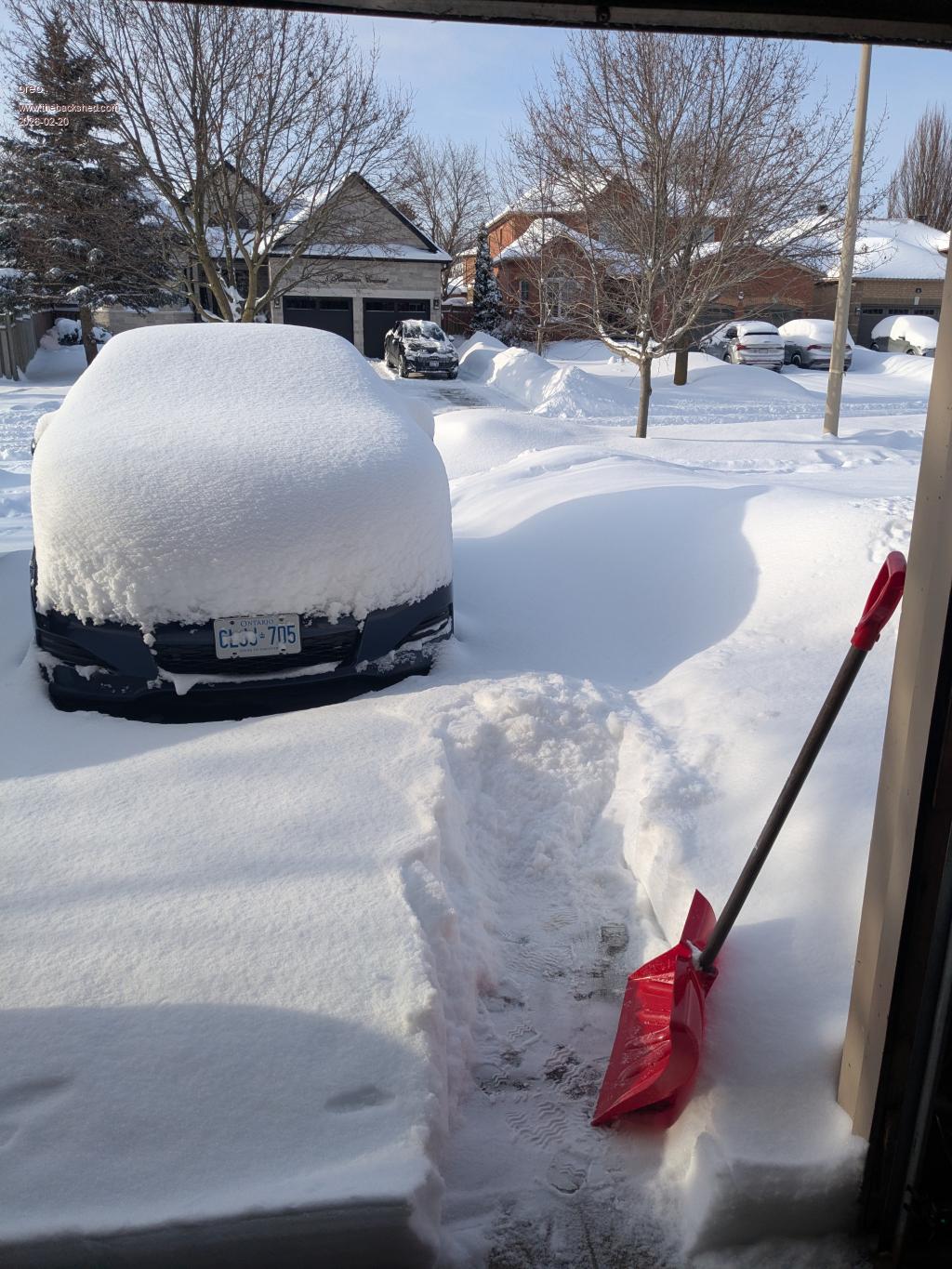 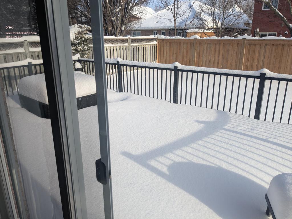 So not bad compared to lots of other areas, but more than we expect. Regarding the inverter, I have done a few things. -the 8 Fets (Q5-Q8 and Q13-Q16) were blown, so I replaced those and the the inverter ran. -I then also replaced the driver transistors, gate resistors and thermal pads just because. -I had a spare power FET and aurduino board mostly built, so I completed those and made another aluminum mounting plate for the power FET board. These new boards were installed into the inverter, and the old ones kept as backup. I had a piece of audio gear that drew a huge inrush current (120A at 120v). I modified it so most it draws now is about 10 amps. This allowed me to greatly reduce the over current trip point of the inverter. Things have been running fine for the last few weeks, although the frequency on this new arduino is not particularly good. So all is good... Greg |
||||
| The Back Shed's forum code is written, and hosted, in Australia. | © JAQ Software 2026 |
