
|
|
Forum Index : Microcontroller and PC projects : PicoMite V6.01.00 betas
| Author | Message | ||||
| lizby Guru Joined: 17/05/2016 Location: United StatesPosts: 3815 |
Use LINE INPUT instead of INPUT. PicoMite, Armmite F4, SensorKits, MMBasic Hardware, Games, etc. on FOTS |
||||
| dddns Guru Joined: 20/09/2024 Location: GermanyPosts: 875 |
Thank you so much, Sir :) That works! I'm blind, it's mentioned in the manual.. |
||||
| mozzie Guru Joined: 15/06/2020 Location: AustraliaPosts: 403 |
G'day Peter, Some further testing of V6.01.00b7 has shown a possible gremlin with the LCD SPI versions. The FRAMEBUFFER MERGE command either locks up the PicoMite, requiring a reboot and occasional loss of all options and program, or "Incorrect Address - Resetting" (I think) possibly depending on whether the buffered driver is used or not. Same with ILI9341, ILI9488 and ST7796S LCD's This does not appear if the LCD is connected to SYSTEM SPI. Also noticed the Waveshare ST7796S LCD with the buffered driver on LCD SPI: CPUSPEED OUTCOME 48-172MHz Works 176-180MHz Corrupt/No display 184-300MHz Works 304-332MHz Corrupt Display - Photo to follow 332-344MHz Works most of the time 344-360MHz Corrupt/No display The LCD SPI / Circles per second wrap @ 180MHz so the above makes sense, possibly just reaching the maximum data rate this display can handle. > option list PicoMite MMBasic RP2350A Edition V6.01.00b7 OPTION LCD SPI GP14,GP15,GP12 OPTION SYSTEM I2C GP20,GP21 OPTION FLASH SIZE 4194304 OPTION COLOURCODE ON OPTION CPUSPEED (KHz) 352000 OPTION LCDPANEL ST7796SBUFF, LANDSCAPE,GP19,GP18,GP17,GP13,INVERT > This has also been discussed in the following thread: https://www.thebackshed.com/forum/ViewTopic.php?TID=18198&P=1#243212 Regards, Lyle. |
||||
| mozzie Guru Joined: 15/06/2020 Location: AustraliaPosts: 403 |
G'day Peter, Further to previous post, this is a photo of the corrupt display on ST7796S: 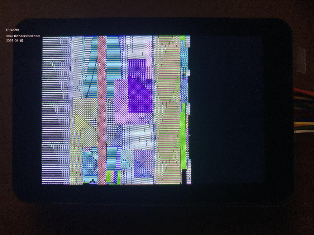 And this is probably the more relevant part of the thread re FRAMEBUFFER https://www.thebackshed.com/forum/ViewTopic.php?FID=16&TID=18198#243343 Regards, Lyle. |
||||
| matherp Guru Joined: 11/12/2012 Location: United KingdomPosts: 11645 |
Just run your Lissajous program all night on an ILI9341 with the buffered driver and no issues. Also tested with the non-buffered driver and again no issues FRAMEBUFFER MERGE 0,b '<======== copy both layers to the screen PicoMite MMBasic RP2350B Edition V6.01.00b7 OPTION SYSTEM SPI GP10,GP11,GP12 OPTION LCD SPI GP2,GP3,GP4 OPTION FLASH SIZE 16777216 OPTION COLOURCODE ON OPTION PICO OFF OPTION CPUSPEED (KHz) 360000 OPTION LCDPANEL ILI9341BUFF, LANDSCAPE,GP26,GP27,GP28,GP5 OPTION PSRAM PIN GP47 Not for me - works perfectly at all speeds (4" ST7796S display) |
||||
| mozzie Guru Joined: 15/06/2020 Location: AustraliaPosts: 403 |
G'day Peter, I notice both Kevin (Bleep)and I are not using PSRAM, is it possible the PicoMite is trying to access it when it doesn't exist? All LCD's work correctly on SYSTEM SPI and with most other commands on LCD SPI, seems strange FRAMEBUFFER MERGE looks like the only culprit. Thanks again for your time. Regards, Lyle. |
||||
| Volhout Guru Joined: 05/03/2018 Location: NetherlandsPosts: 5994 |
Is there a speed difference between SYSTEM SPI and LCD SPI. I seem to remember SYSTEM SPI runs at 8MHz. If there is a higher speed used, LCD wiring/grounding could cause this. Is there a SPI TOUCH involved ? What are the differences between Peter's setup and yours. Volhout PicomiteVGA PETSCII ROBOTS |
||||
| phil99 Guru Joined: 11/02/2018 Location: AustraliaPosts: 3321 |
If the touch chip is connected but not configured in Options a pullup on T_CS will prevent it affecting MISO. 10kΩ works. |
||||
| matherp Guru Joined: 11/12/2012 Location: United KingdomPosts: 11645 |
One thought - please explain how the displays are wired. In my test environment the LCD SPI pins connect ONLY to the LCD. Touch and SDcard are wired to the SYSTEM SPI. This is essential you mustn't have anything other than the display connected to the LCD SPI pins. There is nothing tidy about my wiring and yet it seems completely stable. Every display, touch, SDcard uses different SPI speeds. I am pushing the ST7796SBUFF to the extreme (90MHz) - see the config table below. The default LCD_SPI_SPEED is 25MHz. We need to identify what is different about the configuration of those experiencing issues compared to my setup. 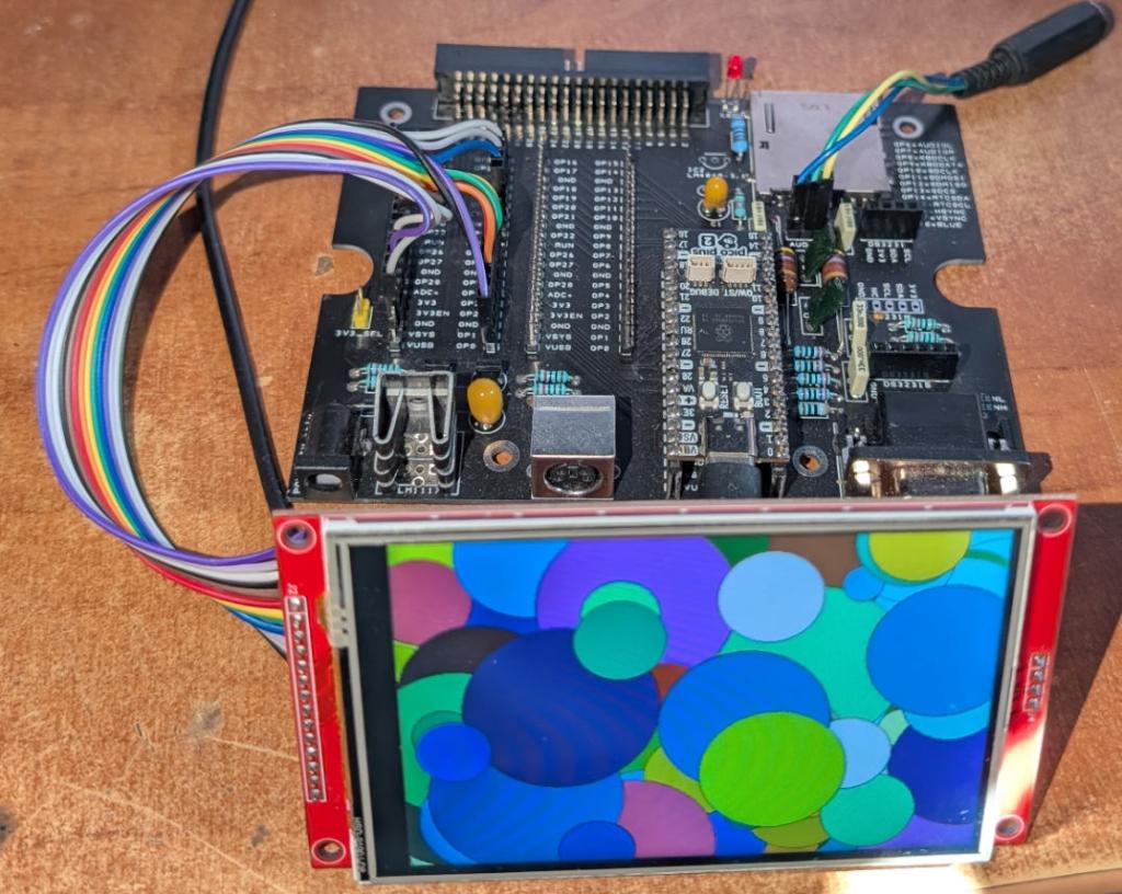 const struct Displays display_details[]={ {0,"", SDCARD_SPI_SPEED, 0, 0, 0, 0, SPI_POLARITY_LOW, SPI_PHASE_1EDGE}, {1,"", SDCARD_SPI_SPEED, 0, 0, 0, 0, SPI_POLARITY_LOW, SPI_PHASE_1EDGE}, {2,"SSD1306I2C", 400, 128, 64, 1, 1, SPI_POLARITY_LOW, SPI_PHASE_1EDGE}, {3,"SSD1306I2C32", 400, 128, 32, 1, 1, SPI_POLARITY_LOW, SPI_PHASE_1EDGE}, {4,"ILI9163", LCD_SPI_SPEED, 128, 128, 16, 0, SPI_POLARITY_LOW, SPI_PHASE_1EDGE}, {5,"ILI9341", 50000000, 320, 240, 16, 0, SPI_POLARITY_LOW, SPI_PHASE_1EDGE}, {6,"ST7735", LCD_SPI_SPEED, 160, 128, 16, 0, SPI_POLARITY_LOW, SPI_PHASE_1EDGE}, {7,"ST7735S", LCD_SPI_SPEED, 160, 80, 16, 0, SPI_POLARITY_LOW, SPI_PHASE_1EDGE}, {8,"SSD1331", LCD_SPI_SPEED, 96, 64, 16, 0, SPI_POLARITY_LOW, SPI_PHASE_1EDGE}, {9,"ST7789", LCD_SPI_SPEED, 240, 240, 16, 0, SPI_POLARITY_LOW, SPI_PHASE_1EDGE}, {10,"ILI9481", LCD_SPI_SPEED, 480, 320, 16, 0, SPI_POLARITY_LOW, SPI_PHASE_1EDGE}, {11,"ILI9488", LCD_SPI_SPEED, 480, 320, 16, 0, SPI_POLARITY_LOW, SPI_PHASE_1EDGE}, {12,"ILI9488P", LCD_SPI_SPEED, 320, 320, 16, 0, SPI_POLARITY_LOW, SPI_PHASE_1EDGE}, {13,"ST7789_135", LCD_SPI_SPEED, 240, 135, 16, 0, SPI_POLARITY_LOW, SPI_PHASE_1EDGE}, {14,"ST7789_320", 50000000, 320, 240, 16, 0, SPI_POLARITY_LOW, SPI_PHASE_1EDGE}, {15,"ILI9488W", LCD_SPI_SPEED, 480, 320, 16, 0, SPI_POLARITY_LOW, SPI_PHASE_1EDGE}, {16,"ST7796S", 50000000, 480, 320, 16, 0, SPI_POLARITY_LOW, SPI_PHASE_1EDGE}, {17,"ST7796SP",50000000, 320, 320, 16, 0, SPI_POLARITY_LOW, SPI_PHASE_1EDGE}, {18,"ST7735S_W", LCD_SPI_SPEED, 128, 128, 16, 0, SPI_POLARITY_LOW, SPI_PHASE_1EDGE}, {19,"GC9A01", LCD_SPI_SPEED, 240, 240, 16, 0, SPI_POLARITY_LOW, SPI_PHASE_1EDGE}, {20,"ILI9481IPS", 12000000, 480, 320, 16, 0, SPI_POLARITY_LOW, SPI_PHASE_1EDGE}, {21,"N5110", NOKIA_SPI_SPEED, 84, 48, 1, 1, SPI_POLARITY_LOW, SPI_PHASE_1EDGE}, {22,"SSD1306SPI", LCD_SPI_SPEED, 128, 64, 1, 1, SPI_POLARITY_LOW, SPI_PHASE_1EDGE}, {23,"ST7920", ST7920_SPI_SPEED, 128, 64, 1, 1, SPI_POLARITY_HIGH, SPI_PHASE_2EDGE}, {24,"", TOUCH_SPI_SPEED, 0, 0, 0, 0, SPI_POLARITY_LOW, SPI_PHASE_1EDGE}, {25,"SPIReadSpeed", 12000000, 480, 320, 16, 0, SPI_POLARITY_LOW, SPI_PHASE_1EDGE}, {26,"ST7789RSpeed", 6000000, 320, 240, 16, 0, SPI_POLARITY_LOW, SPI_PHASE_1EDGE}, {27,"", SLOW_TOUCH_SPEED, 0, 0, 0, 0, SPI_POLARITY_LOW, SPI_PHASE_1EDGE}, {28,"User", 0, 0, 0, 0, 0, 0 ,0}, {29,"Dummy", 0, 0, 0, 0, 0, 0 ,0}, {30,"Dummy", 0, 0, 0, 0, 0, 0 ,0}, {31,"Dummy", 0, 0, 0, 0, 0, 0 ,0}, {32,"Dummy", 0, 0, 0, 0, 0, 0 ,0}, {33,"Dummy", 0, 0, 0, 0, 0, 0 ,0}, {34,"Dummy", 0, 0, 0, 0, 0, 0 ,0}, {35,"Dummy", 0, 0, 0, 0, 0, 0 ,0}, {36,"SSD1963_4", 0, 0, 0, 0, 0, 0 ,0}, {37,"SSD1963_5", 0, 0, 0, 0, 0, 0 ,0}, {38,"SSD1963_5A", 0, 0, 0, 0, 0, 0 ,0}, {39,"SSD1963_7", 0, 0, 0, 0, 0, 0 ,0}, {40,"SSD1963_7A", 0, 0, 0, 0, 0, 0 ,0}, {41,"SSD1963_8", 0, 0, 0, 0, 0, 0 ,0}, {42,"ILI9341_8", 0, 0, 0, 0, 0, 0 ,0}, {43,"SSD1963_4_16", 0, 0, 0, 0, 0, 0 ,0}, {44,"SSD1963_5_16", 0, 0, 0, 0, 0, 0 ,0}, {45,"SSD1963_5A_16" , 0, 0, 0, 0, 0, 0 ,0}, {46,"SSD1963_7_16", 0, 0, 0, 0, 0, 0 ,0}, {47,"SSD1963_7A_16", 0, 0, 0, 0, 0, 0 ,0}, {48,"SSD1963_8_16", 0, 0, 0, 0, 0, 0 ,0}, {49,"ILI9341_16", 0, 0, 0, 0, 0, 0 ,0}, {50,"IPS_4_16", 0, 0, 0, 0, 0, 0 ,0}, {51,"SSD1963_5E_16", 0, 0, 0, 0, 0, 0 ,0}, {52,"SSD1963_7E_16", 0, 0, 0, 0, 0, 0 ,0}, {53,"ILI9486_16", 0, 0, 0, 0, 0, 0 ,0}, {54,"VIRTUAL_C", 0, 320, 240, 0, 0, 0, 0}, {55,"VIRTUAL_M", 0, 640, 480, 0, 0, 0, 0}, {56,"VS1053slow", 200000, 0, 0, 0, 0, SPI_POLARITY_LOW, SPI_PHASE_1EDGE}, {57,"VS1053fast", 4000000, 0, 0, 0, 0, SPI_POLARITY_LOW, SPI_PHASE_1EDGE}, #if defined(PICOMITE) && defined(rp2350) {58,"ST7796SPBUFF",90000000, 320, 320, 16, 0, SPI_POLARITY_LOW, SPI_PHASE_1EDGE}, {59,"ILI9341BUFF",50000000, 320, 240, 16, 0, SPI_POLARITY_LOW, SPI_PHASE_1EDGE}, {60,"ST7796SBUFF", 90000000, 480, 320, 16, 0, SPI_POLARITY_LOW, SPI_PHASE_1EDGE}, {61,"ILI9488BUFF", 45000000, 480, 320, 16, 0, SPI_POLARITY_LOW, SPI_PHASE_1EDGE}, {62,"ILI9488PBUFF", 45000000, 320, 320, 16, 0, SPI_POLARITY_LOW, SPI_PHASE_1EDGE}, {63,"ILI9488WBUFF", 45000000, 480, 320, 16, 0, SPI_POLARITY_LOW, SPI_PHASE_1EDGE}, {64,"ST7789_320BUFF", 50000000, 320, 240, 16, 0, SPI_POLARITY_LOW, SPI_PHASE_1EDGE}, #endif |
||||
| Volhout Guru Joined: 05/03/2018 Location: NetherlandsPosts: 5994 |
Hi Peter, Measured in a RP2350A equipped Game*Mite the SPI clock on the ILI9341 is 42MHz. This is exactly 1/6th of the CPU speed (252MHz) of this Game*Mite. So SPI is not running at LCD_SPI_SPEED (25MHz) or the 50MHz ({5,"ILI9341", 50000000,....) that is in the shown information above. Of coarse this is SYSTEM SPI, and not buffered LCD SPI. But it could explain the relation they see with the CPU speed. Volhout Edited 2025-08-15 20:41 by Volhout PicomiteVGA PETSCII ROBOTS |
||||
| Bleep Guru Joined: 09/01/2022 Location: United KingdomPosts: 817 |
Hi Peter, From other thread:- I've tested the Framebuffer Merge, as it looked like there might be a problem on the 6.01.00b and I do believe there is a problem. I am using :- PicoMite MMBasic USB RP2350A Edition V6.01.00b7 OPTION SERIAL CONSOLE COM2,GP8,GP9,BOTH OPTION SYSTEM SPI GP18,GP19,GP16 OPTION LCD SPI GP26,GP27,GP28 OPTION SYSTEM I2C GP20,GP21 OPTION FLASH SIZE 4194304 OPTION COLOURCODE ON OPTION KEYBOARD US OPTION CPUSPEED (KHz) 360000 OPTION LCDPANEL CONSOLE 7,,, 50,NOSCROLL OPTION DISPLAY 40, 80 OPTION LCDPANEL ST7796S, LANDSCAPE,GP12,GP13,GP14,GP15 OPTION LCD BACKLIGHT 50 OPTION TOUCH GP17,GP7 OPTION SDCARD GP22 OPTION AUDIO GP10,GP11', ON PWM CHANNEL 5 OPTION RTC AUTO ENABLE OPTION DEFAULT FONT 7, 1 The LCD SPI is only connected to the LCD, nothing else. I have tried various CPU speed setting, again, no difference. The simpelest program to demonstrate is:- Framebuffer Create Framebuffer Layer Framebuffre write f Framebuffer Merge 'Or Framebuffer Merge 0 'Or Framebuffer Merge 0,r,100 This will completely lock up the Pico, no output to LCD screen or USB console, though the heartbeat is still flashng, it requires a power off and on. I have done a full Option Reset and manually put everything back in and the problem was still present. Regards, Kevin. Edited 2025-08-15 20:52 by Bleep |
||||
| matherp Guru Joined: 11/12/2012 Location: United KingdomPosts: 11645 |
SPI speeds can only be simple divisors of the system clock. The system chooses the divisor that gives a clock speed less than or equal to that requested so what you are seeing is completely correct. Kevin Please simplify your options to try and make it work. I would start with removing the display as a console Edited 2025-08-15 20:58 by matherp |
||||
| Volhout Guru Joined: 05/03/2018 Location: NetherlandsPosts: 5994 |
Aha... so if I set the Game*Mite CPU SPEED to 250MHz (versus 252MHz) the SPI will switch from 42MHz to 50MHz, and the Game*Mite will be faster. It's worth a try... Volhout EDIT: it does not choose a divider ratio lower than 6. So 250MHz and 240MHz and 220MHz all result in a slower SPI clock. The only way to increase the SPI clock is to increase the CPU SPEED. 300MHz result in 50MHz. Edited 2025-08-15 21:21 by Volhout PicomiteVGA PETSCII ROBOTS |
||||
| Bleep Guru Joined: 09/01/2022 Location: United KingdomPosts: 817 |
Hi Peter, Did a Option Reset, so completly default, then only put back the LCD SPI and the LCD definition itself, then using the simpelest test below, the screen goes white, then clears, but the Pico looks like it has rebooted, ie I'm seeing the re-initialisation of the USB ports message, as below. > run > US USB Keyboard Connected on channel 1 > USB Mouse Connected on channel 2 If I attempt a background merge with:- Framebuffer Merge 0,b I do get a invalid address error. > RUN Error: Invalid address - resetting > > US USB Keyboard Connected on channel 1 > USB Mouse Connected on channel 2 Framebuffer Create Framebuffer Layer Framebuffre write f Framebuffer Merge 'Or Framebuffer Merge 0 'Or Framebuffer Merge 0,r,100 Hope this helps. Regards Kevin. |
||||
| matherp Guru Joined: 11/12/2012 Location: United KingdomPosts: 11645 |
Maximum SPI speed is CPU/2 so at 250MHz divide by 1 gives 125MHz (much too much), divide by 2 gives 62.5MHz (too much), divide by 3 gives 41.666MHz Kevin Please confirm this is a USB version only issue (PSRAM makes no difference) 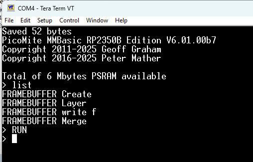 Edited 2025-08-15 22:16 by matherp |
||||
| mozzie Guru Joined: 15/06/2020 Location: AustraliaPosts: 403 |
G'day, I forgot to mention in the first post that this appears to be related to the RP2350 only, possibly only RP2350A only. Some further testing, I can read / copy from / copy to the screen so I figure this means the SPI can read ok The touch controller is pulled high by 2 parallel 10k res, "two you say - to be sure, to be sure...." I am using the "PicoMite LCD backpack" as printed in Silicon Chip magazine, nothing connected to the LCD SPI except the touch controller, disabled by resistors mentioned above. ST7796S touch is I2C and no SD card inserted so should be no interference there. ILI9341 will work with MERGE on ILI9341BUFF driver, hadn't tried this before. ILI9341 won't work with MERGE on ILI9341 driver - "Error: Invalid address - resetting" PicoMite RP2350 version: 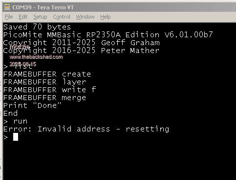 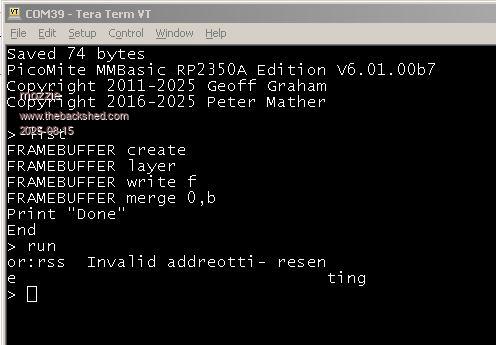 > option list PicoMite MMBasic RP2350A Edition V6.01.00b7 OPTION LCD SPI GP18,GP19,GP16 OPTION FLASH SIZE 4194304 OPTION COLOURCODE ON OPTION CPUSPEED (KHz) 150000 OPTION LCDPANEL ILI9341, LANDSCAPE,GP14,GP13,GP12 > Regards, Lyle. Edited 2025-08-15 22:43 by mozzie |
||||
| Volhout Guru Joined: 05/03/2018 Location: NetherlandsPosts: 5994 |
@Peter, CPUSPEED SPI CLOCK DIVIDER 126 32 4 150 38 4 180 45 4 220 37 6 252 42 6 300 50 6 Apparently the clock divider uses even divider ratio's only. That is where I got confused. I was expecting divide by 5 at 250MHz. No bug, no issue, only building up knowledge. Volhout PicomiteVGA PETSCII ROBOTS |
||||
| matherp Guru Joined: 11/12/2012 Location: United KingdomPosts: 11645 |
No: as I explained above the base clock for SPI is CPU/2 which is then divided by 1,2,3,4,5... SPI by definition needs 2 base clocks as it has to output a bit and read a bit in one SPI clock duration Edited 2025-08-16 00:16 by matherp |
||||
| Bleep Guru Joined: 09/01/2022 Location: United KingdomPosts: 817 |
Hi Peter, Sorry for the delay I've just been out MTB'ing before it gets too hot. ;-) I dont have a non USB 2350, so I've installed the non USB firmware onto my USB. I can confirm that the Merge command does work on :- PicoMite MMBasic RP2350A Edition V6.01.00b7 OPTION SYSTEM SPI GP18,GP19,GP16 OPTION LCD SPI GP26,GP27,GP28 OPTION FLASH SIZE 4194304 OPTION COLOURCODE ON OPTION CPUSPEED (KHz) 150000 OPTION LCDPANEL ST7796S, LANDSCAPE,GP12,GP13,GP14,GP15 As does the Lissajous program now as well. :-) Regards, Kevin. |
||||
| matherp Guru Joined: 11/12/2012 Location: United KingdomPosts: 11645 |
See answer on the other thread |
||||
| The Back Shed's forum code is written, and hosted, in Australia. | © JAQ Software 2026 |
