
|
|
Forum Index : Microcontroller and PC projects : Pico Radar
| Author | Message | ||||
palcal Guru Joined: 12/10/2011 Location: AustraliaPosts: 2039 |
Thanks all, I got it working OK. "It is better to be ignorant and ask a stupid question than to be plain Stupid and not ask at all" |
||||
TassyJim Guru Joined: 07/08/2011 Location: AustraliaPosts: 6547 |
A different version where the target has grown a tail. radar2.zip DIM cro ' used for timing with CRO DIM FLOAT Yscale = 4000/MM.VRES ' 400 = max reading = 4M DIM FLOAT Xscale = -Yscale '-8000/mm.hres 'keep x and y the same DIM Xmid = MM.HRES/2 DIM multi = 0 ' single or multiple targets DIM samplerate = 5 ' plot every nn signals DIM tailsize = 20 ' length of tail I use a spare pin as timing. This can be ignored. The plotting takes 40mS For full range, set Yscale as 8000/mm.vres plotting every 2 or 5 readings looks good to me. A tail longer than 20 causes problems. I am not sure why yet. You will need to change line 39/40 and 49/50 to suit your serial port settings Jim Footnote added 2025-12-10 06:38 by TassyJim The family are awake now so I can se that a tail doesn't work very well with multiple targets. The "number one" target keeps changing between targets and confuses the tail. It will take some maths to guess which tail belongs to who. Footnote added 2025-12-10 07:02 by TassyJim I will change the tail from line to points. That should look better with multiple targets. VK7JH MMedit |
||||
| lizby Guru Joined: 17/05/2016 Location: United StatesPosts: 3813 |
Ok. I had some 2mm female header. Soldered it on to a 2.54m female header after bending pins on both, and plugged that into the white connector on the HLK-LD2450. I plugged it into a USB-serial module, plugged it into my PC, set the baud rate at 256000, and could see characters. Mostly not printable ASCII. I plugged it in to a Pico1 with latest firmware and ILI9488 LCD, downloaded the .bas file from Radar_v.1.1.2-blit.zip, set the serial port (double checked pin # and Rx/Tx, but could be wrong), and got this: 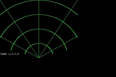 So that's a good start, but I have no dot, so 2 questions: How should I determine whether I'm getting serial input, and Where do I make changes for the ILI9488 480x320 LCD? PicoMite, Armmite F4, SensorKits, MMBasic Hardware, Games, etc. on FOTS |
||||
| TassyJim Guru Joined: 07/08/2011 Location: AustraliaPosts: 6547 |
Try this ARC MM.HRES/2,MM.VRES,60,,285,75,RGB(GREEN) ARC MM.HRES/2,MM.VRES,120,,285,75,RGB(GREEN) ARC MM.HRES/2,MM.VRES,180,,298,62,RGB(GREEN) ARC MM.HRES/2,MM.VRES,240,,318,42,RGB(GREEN) LINE 0,0,MM.HRES/2,MM.VRES,,RGB(GREEN) LINE MM.HRES/2,0,MM.HRES/2,MM.VRES,,RGB(GREEN) LINE MM.HRES,0,MM.HRES/2,MM.VRES,,RGB(GREEN) LINE 0,150,MM.HRES/2,MM.VRES,,RGB(GREEN) LINE MM.HRES,150,MM.HRES/2,MM.VRES,,RGB(GREEN) The target should appear after it sees movement. Wave a hand in front should be enough. Jim VK7JH MMedit |
||||
| palcal Guru Joined: 12/10/2011 Location: AustraliaPosts: 2039 |
If I open a terminal and run the code it prints out the information as it changes. "It is better to be ignorant and ask a stupid question than to be plain Stupid and not ask at all" |
||||
| ville56 Guru Joined: 08/06/2022 Location: AustriaPosts: 550 |
lizby, if you open a console terminal you can see if the datastream from the sensor can be synced or sync is lost and regained, you can type P for printing the converted data and when pressing Z it displays also data when there is no target tracked. This situation will not display the ball on the LCD as there is no target to be displayed. For getting the sensor to recognise a target waveing a hand in front of the sensor usually is sufficient. Pressing H prints some help text. Gerald 73 de OE1HGA, Gerald |
||||
| ville56 Guru Joined: 08/06/2022 Location: AustriaPosts: 550 |
have just made a version that adapts the radar-grid automatically to the lcd (or whatever is used) size and also extends the straight lines up to the lcd borders. Also arc is replaced by circle because its easier to code and probably faster. The BLIT technique is kept, as it really saves cpu cycles and/or ram compared with redrawing the grid or using layers. Introduced a new sub "get_intercept" which gets the nearest intercept point with one of the lcd borders in order to draw the lines up to the border. It's a simple intercept calculation of 2 lines, border and gridline using good ole substituion method. See my comments in the code .... Radar_v.1.1.2-blit-2.zip Gerald 73 de OE1HGA, Gerald |
||||
| lizby Guru Joined: 17/05/2016 Location: United StatesPosts: 3813 |
Beautiful screen now with Radar_v.1.1.2-blit-2.bas. 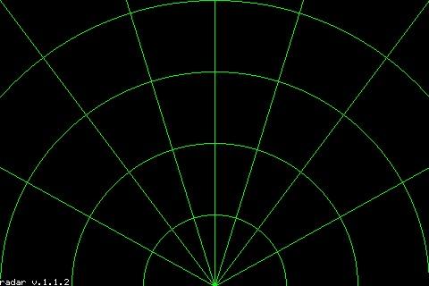 But still no dot. I swapped Rx & Tx just in case, but no difference. Tomorrow I'll hook up those Rx & Tx pins from the PicoMite through a USB-serial module to confirm whether I've got them right. BTW, "H", "P", and "Z" did not result in any output. Are the arcs at any predictable distance from the module? ~ Edited 2025-12-10 12:01 by lizby PicoMite, Armmite F4, SensorKits, MMBasic Hardware, Games, etc. on FOTS |
||||
| TassyJim Guru Joined: 07/08/2011 Location: AustraliaPosts: 6547 |
Try this short test program ' OPTION EXPLICIT OPTION DEFAULT INTEGER OPTION BASE 0 DIM n, rec$ SETPIN GP5, GP4, COM2 OPEN "com2: 256000" AS #3 DO rec$ = INPUT$(255,#3) IF LEN(rec$)>0 THEN FOR n = 1 TO LEN(rec$) PRINT HEX$(ASC(MID$(rec$,n,1)),2); IF (n MOD 40) = 0 THEN PRINT NEXT n ENDIF LOOP Change the setpin and open com lines to match your setup The output should look like this: AAFF 03006D810E81000068010000 000000000000000000000000000055CC AAFF 030084810881000068010000 000000000000000000000000000055CC AA FF03009781018100 0068010000000000000000000000000000000055CC AA FF03009E81F58000 Jim Edited 2025-12-10 13:18 by TassyJim VK7JH MMedit |
||||
| ville56 Guru Joined: 08/06/2022 Location: AustriaPosts: 550 |
lizby, - you still do not get any data from the sensor, if the program does not react on keys pressed, there is no sync with the sensor. Again, please check the wiring and the com-port settings in the program or your sensor may be dead. Are you using 5 Volts for Vcc as stated in the datasheet? I Think 3.3 Volts may be too low if used. The little beast draws some current for the transmitter .... I've connected my sensors Vcc to the Vbus pin on the pico. A good GND connection also always helps. If you have a scope, check the sensor TX line for bits coming along. From the short ones you can calculate the baudrate. I also use one of this 10$ USB logic analyzers from Aliexpress. They work up to 20 Mhz reliably and let you have the data from the serial line also decoded into hex or ascii. Have modified their python script a bit to also show control chars, Great for debugging. edit (forget the rubbish I wrote before): - The arcs can be made to show a predictible distance. the factors are in the program at the lines const v_fact = mm.vres/8000 const h_fact = mm.hres/6200 set them to whatever pixel/mm you want to show on the display, but make sure both corrdinates have the same factor in this case. Gerald Edited 2025-12-10 18:26 by ville56 73 de OE1HGA, Gerald |
||||
| PhenixRising Guru Joined: 07/11/2023 Location: United KingdomPosts: 2005 |
I wonder what would be the best sensor technology for clip-on (or permanent) vehicle guidance. I was reversing the van up to the doors of a factory in the dark. The bright lighting around the building was putting glare on my reversing camera. All kinds of obstacles to avoid. I ended-up inching along and periodically jumping out to walk around the van to be sure I had clearance. I "expressed my frustration" to a regular truck driver there and he said that they had to deal with this problem every day. Battery-powered clip-on device with wireless comm's? Thinking clip-on (or magnetic) to allow placement at the area of interest. Edited 2025-12-10 23:54 by PhenixRising |
||||
| v.lenzer Senior Member Joined: 04/05/2024 Location: GermanyPosts: 124 |
As promised, I connected the RD-03D today for testing purposes. Nothing happened. I checked the connections and tried all the possible combinations. Has anyone had success with the radar_v.1.1.2 software or other programs? I'd also like to remain compatible with Gerald's "Blit version" to participate in future expansions and improvements. Does anyone have any idea why my network lines are wider than Gerald's? Is it the firmware? In the line command, I entered ",", for LW. This sets LW=1. PS: I just noticed that Jim has already worked with this RD-03D (using the Poodle program). His software doesn't work for me either. So I must be doing something wrong with the connections. I'll keep working on it. Edited 2025-12-11 20:57 by v.lenzer Best wishes! Joachim |
||||
| ville56 Guru Joined: 08/06/2022 Location: AustriaPosts: 550 |
Joachim, just rechecked with the RD-03D datasheet. The defaults should be the same as with LD2450, regarding protocol, serial baudrate and format. So I guess the other parts of the LD2450 protocol (modes and settings etc.) are the same as well. Try it with Jims test program, if that prints out data having "AAFF0300" then 24 bytes of payload and then "55CC" you can be sure the sensor deliveres data. for this connect the tx line from the sensor to GP5 and the RX to GP4 or change the pins and com in the OPEN statement accordingly. Jims testprogram ' OPTION EXPLICIT OPTION DEFAULT INTEGER OPTION BASE 0 DIM n, rec$ SETPIN GP5, GP4, COM2 OPEN "com2: 256000" AS #3 DO rec$ = INPUT$(255,#3) IF LEN(rec$)>0 THEN FOR n = 1 TO LEN(rec$) PRINT HEX$(ASC(MID$(rec$,n,1)),2); IF (n MOD 40) = 0 THEN PRINT NEXT n ENDIF LOOP The sensor draws over 200mA at 5V and the datasheet recommends 2x 100nF bypass capacitors between 5V and Gnd close to the sensor. Depending on your PS and wire length this may be necessary. I use the Vbus pin to get the 5V from USB to the sensor, no 100nF caps though. Wires are abt 15 cm. You can also try with a terminal program (connecting the sensor to a Serial->USB converter) that can display the received bytes in hex. I use RealTerm for that. 256000 baud, 1 stopbit, no parity. Gerald Edit: please use the latest V6.01.00RC25 as this is also the version I develop currently with. There may well by a different behaviour of the arc/circle/line drawing compared to earlier versions. Edited 2025-12-12 01:19 by ville56 73 de OE1HGA, Gerald |
||||
| v.lenzer Senior Member Joined: 04/05/2024 Location: GermanyPosts: 124 |
Hi Gerald! Jim's Poodle program finally got it working with the RD-03D. Before that, I had measured with an oscilloscope. It might have just been a loose connection. Then I switched back to the ILI9341 display and reset the options. I don't know why, but the lines in the radar grid are now as thin as yours. It couldn't have been the display change because on the Zero, which is housed in a case and runs the radar software, I still have the thicker lines with an ILI9341 LCD that's never been changed. Anyway, whatever the reason, everything is working now and version 1.1.2.blit.2 is running. I've done the firmware upgrade. We should rethink the program name and versioning. I'd like to follow your suggestion since you developed the program. Best wishes! Joachim |
||||
| ville56 Guru Joined: 08/06/2022 Location: AustriaPosts: 550 |
Joachim, good to hear it was just some hardware issue and that the RD-03D is compatible so far. I've had a logic error in the blit.2 version regarding the blit save/restore logic in multi-target configuration. Hopefully it's rectified now in this new version. Tests looked good. New command "R" introduced to redraw the grid-lines. Reason is that it managed to spoil the screen occasionally but I dunno why yet. Regarding the verion .... I've renamed it now to "Radar-V2.0.0" and yes, I'm the original author of most of the code BUT if I publish code in the forum it belongs to all members of course and everybody is free to do whatever he/she wants to do with it. That is part of the idea of this forum, I suppose. And you contibuted the grid-lines idea so it's also part of your work and hopefully others will contribute too. Radar-V2.0.0.zip Have fun, Gerald 73 de OE1HGA, Gerald |
||||
| lizby Guru Joined: 17/05/2016 Location: United StatesPosts: 3813 |
Working now, thanks, all. The pin labelled "0V" on my PCB was not actually connected to 0V. 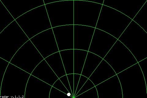 This will be fun to play with. I'd like to map it to the area around my shed. How far out does it range, and any suggestions as to how to label the arc distances from the module--perhaps at the intersection of each arc with the line which goes to the upper right corner? (Sorry to be asking these questions, when I could investigate. AI has me spoiled for asking questions. Nice also to have some non-artificial intelligence to query.) ~ Edited 2025-12-12 06:30 by lizby PicoMite, Armmite F4, SensorKits, MMBasic Hardware, Games, etc. on FOTS |
||||
| ville56 Guru Joined: 08/06/2022 Location: AustriaPosts: 550 |
Lizby, no need to interrogate AI, this is natural NI (No Intelligence) answering  - as I wrote, a good GND connection is always your friend (had that already myself several times) - the max range of the sensor is 8000 mm as of the datasheet. It certainly also depends on the size of the target how far the actual range will be. - the attached V2.0.1 has now distance labels. You can modify the parameters as you like. They are at line 101 onwards, please read the comments. But labeling in feet and inches may be a bit of a challenge ... at least for me as a metric guy. Radar-V2.0.1.zip Gerald 73 de OE1HGA, Gerald |
||||
| lizby Guru Joined: 17/05/2016 Location: United StatesPosts: 3813 |
Thank you very much. 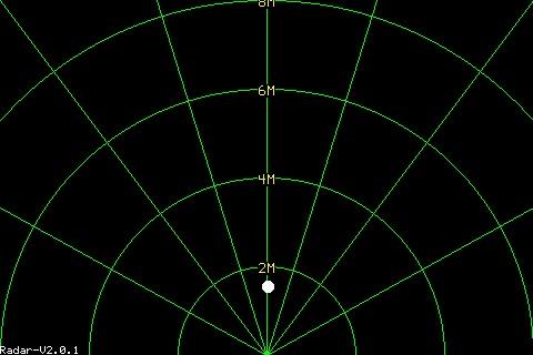 I changed to meters instead of mm and increased the font size. I'm a U.S. citizen, so grew up with feet and inches, but am a Canadian permanent resident, so familiar enough with metric. On the other hand, dimensional lumber is still sold in Canada in feet and inches (2x4 studs, 4x8x1/2 plywood), and the carpenters I know work in feet and inches (though I did hire a laborer once who could not read a tape in feet and inches and fractions of an inch). What does the entry of "1" do? I tried it and saw no difference in the screen and no files produced. I'm tempted to map movement by writing "01 " through "99 " to the screen when the dot location changes significantly (about 3 character-widths horizontally and/or one character height vertically, and also, with a time stamp and location, to a file. Then I could replay steps 1-99. ~ Edited 2025-12-13 04:57 by lizby PicoMite, Armmite F4, SensorKits, MMBasic Hardware, Games, etc. on FOTS |
||||
| ville56 Guru Joined: 08/06/2022 Location: AustriaPosts: 550 |
You could as well have hired me, still have my problems with fraktions of inches  If you type 1 or M you switch between single (1) and multiple (M) target mode. So you need at least 2 moving targets to see the difference. 73 de OE1HGA, Gerald |
||||
| Amnesie Guru Joined: 30/06/2020 Location: GermanyPosts: 763 |
Hi, this is really amazing and reminds me of the ALIEN movies in which there was some kind of handscanner to detect the aliens. Also one could built a sentry gun (same movie) and even the graphical user interface for that. Wow  I've ordered some sensor modules, too. Very interesting project! For what do you use it? If it can detecs cats and dogs I have many ideas  Greetings Daniel |
||||
| The Back Shed's forum code is written, and hosted, in Australia. | © JAQ Software 2026 |
