
|
|
Forum Index : Microcontroller and PC projects : PicoMite Alpha Firmware
| Author | Message | ||||
| Volhout Guru Joined: 05/03/2018 Location: NetherlandsPosts: 6000 |
I am looking into the ADC's a bit. Using software a13 This piece of software, It samples all 3 ADC's in sequence, stores the data in an array, and measures how fast we can sample. That is roughly 80us. Then I print the array to the terminal in a CSV format, so I can copy and paste it into excel to check accuracy. 'adc run 3 channels 'adc channels pi pico:GP26(adc0), GP27(adc1),GP28(adc2) 'psu control: GP23 'initialize ADC's SetPin GP26,ain:SetPin GP27,ain:SetPin GP28,ain 'force PSU to PWM mode 'SetPin GP23,dout 'Pin(GP23)=1 'do a brute force sampling on all 3 channels n=1000 Dim v(n,3) Timer =0 For i=1 To n v(i,1)=Pin(GP26) v(i,2)=Pin(GP27) v(i,3)=Pin(GP28) Next i t=Timer Print "one adc conversion takes ";1000*t/(3*n);" us" 'send the data out as a csv format for acceptance in excel Print "sample , GP26 , GP27 , GP28" For i=1 To n Print i;" , ";v(i,1);" , ";v(i,2);" , ";v(i,3) Next i 2 observations 1/ I cannot control GP23 (the pi pico datasheet says that forcing the power supply in PWM mode, by setting GP23 high) will lower the ripple at the 3.3V, and thus make the ADC jitter lower (3.3V is used as Vref). 2/ Maybe there is somethin wrong with my code, but the values stored in v(i,1) and v(i,2) and v(i,3) are all values from adc2 (GP28). Simple test: connect GP28 to 3V, the rest to 0v, you will see all values being 3V. FYI: I have tested the adc independent from the commandline, and then they work independent. But in this program (running at full MMBasic speed) all adc's measure the same value. Please shoot holes in my program. I am not sure what I did wrong. Volhout edit: I found the bug. Although there are 3 adc's, the setpin command decides what pin is multiplexed to the adc. so: setpin gp26,ain ?pin(gp26) setpin gp27,ain ?pin(gp27) setpin gp28,ain ?pin(gp28) Works But setpin gp26,ain setpin gp27,ain setpin gp28,ain ?pin(gp26) ?pin(gp27) ?pin(gp28) outputs only adc2 (gp28) data Edited 2021-06-03 20:11 by Volhout PicomiteVGA PETSCII ROBOTS |
||||
| matherp Guru Joined: 11/12/2012 Location: United KingdomPosts: 11673 |
a14 PicomiteV5.07.00a14.zip Fixes bug in using multiple ADC channels NEW temporary option OPTION POWER source ' source can be PWM or PFM defaults to PFM. Set at top of program if required IR receive implemented and tested IR send implemented - not tested Pulsein, pulse implemented - not tested PORT command and function enabled - still not tested UPDATED at 10:35UTC Now includes UPDATE FIRMWARE command Edited 2021-06-03 20:36 by matherp |
||||
| Volhout Guru Joined: 05/03/2018 Location: NetherlandsPosts: 6000 |
Thanks Peter, That worked. Using a14. All 3 channels are independent now. The ADC is not bad. Midrange noise level is +/- 2.5mV. That is 5mV/1600mV = 1:320 => 8.4 effective bit. At full speed. And no special precautions like low pass filters. 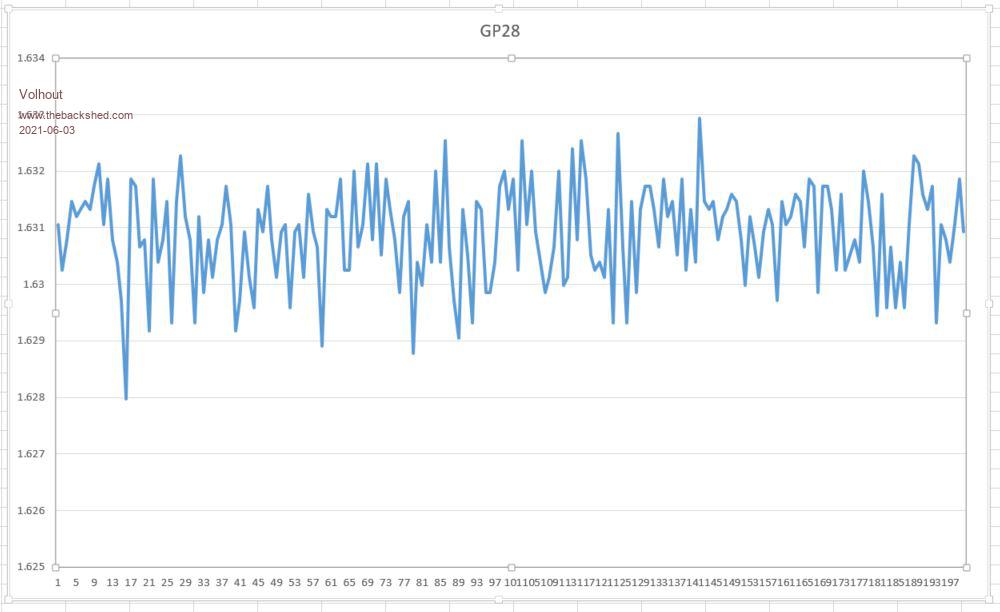 When sampling a single channel in a for-next loop the 80us conversion time is not met. That is proven when a 0.6V 2kHz signal is measured. It is closer to 100us. 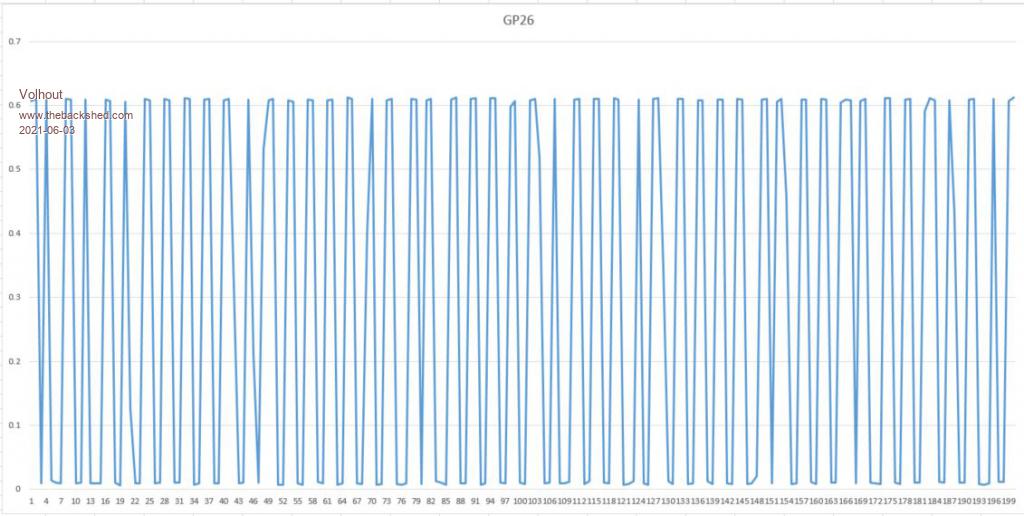 I will see if I can improve the effective bit a bit more with HW means. Volhout Edited 2021-06-03 20:40 by Volhout PicomiteVGA PETSCII ROBOTS |
||||
| matherp Guru Joined: 11/12/2012 Location: United KingdomPosts: 11673 |
The ADC code does 10x oversampling and discards the top and bottom 2 |
||||
| Mixtel90 Guru Joined: 05/10/2019 Location: United KingdomPosts: 8981 |
Is HUMID returning integers instead of longs for the DHT11 or am I doing something wrong? Mick Zilog Inside! nascom.info for Nascom & Gemini Preliminary MMBasic docs & my PCB designs |
||||
| matherp Guru Joined: 11/12/2012 Location: United KingdomPosts: 11673 |
DHT11 resolution only 1deg and 1% |
||||
| Mixtel90 Guru Joined: 05/10/2019 Location: United KingdomPosts: 8981 |
Thanks. :) Mick Zilog Inside! nascom.info for Nascom & Gemini Preliminary MMBasic docs & my PCB designs |
||||
| Volhout Guru Joined: 05/03/2018 Location: NetherlandsPosts: 6000 |
Thank you for the info. This is a nice approach for now. Once we have better visibility on the performance of MMBasic it may be preferred to also tune the adc algorythm. Using the adc for measurements goes best when you can have a fixed sample frequency. Something running of a timer (not depending on the execution speed of MMBasic). I remember you did something like that for the H7. Anyway, happy enough it works. Is there a possibility for the user control of GP23 ? Regards, Volhout PicomiteVGA PETSCII ROBOTS |
||||
| matherp Guru Joined: 11/12/2012 Location: United KingdomPosts: 11673 |
|
||||
| Volhout Guru Joined: 05/03/2018 Location: NetherlandsPosts: 6000 |
Just an observation. Writing a value to an array takes time. But the time it takes is depending on the size of the array. dim v(100,2) v(50,2)=10 is faster than dim v(100,5) v(50,2)=10 I am not speaking about the time to dim the array, but the time to do the writing of the value. (of coarse his is tested in a loop, using Timer). Not an issue, the difference is few percent, but I was under the impression that arrays worked with pointers, and then there would be no difference in where you write in that array. Edited 2021-06-04 00:15 by Volhout PicomiteVGA PETSCII ROBOTS |
||||
| matherp Guru Joined: 11/12/2012 Location: United KingdomPosts: 11673 |
Proposal The Picomite has more flexibility over which pins are used for what compared to the STM32 or PIC32. In order to make use of this I propose as follows: Special functions will not be directly assigned to pins, instead SETPIN will be used to associate a particular function with a pin e.g. SETPIN I2C0 p1, p2 SETPIN PWM1A p1 SETPIN SPI0 p1,p2,p3 This will mean that the use of setpin is mandatory before using things like I2C OPEN Overall the flexibility is as follows: Up to 16 PWM with up to 8 different frequencies allocatable to any pin 1, or 2 I2C allocatable as per pic 1, or 2 SPI allocatable as per pic 1, or 2 UART allocatable as per pic 4 Count pins allocatable to any pin (could be more than 4 if there is a requirement?) 1 IR pin allocatable to any pin PIO functions to be allocated to a pin in the same sort of way - mechanism TBD I don't know at the moment if I2C etc. have to be allocated in the logical groups on the chart - will see when testing. Thoughts? 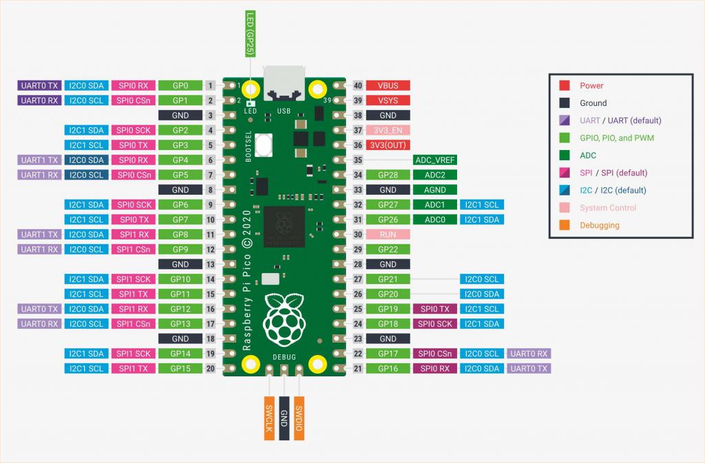 Edited 2021-06-04 01:11 by matherp |
||||
| CaptainBoing Guru Joined: 07/09/2016 Location: United KingdomPosts: 2171 |
Oh yes please!!! Fantastically flexible pin assignment. Perhaps defaults should be set to maintain as much backward compatibility with older software. A mandatory setpin means a (small) re-write of ported software and a lack of compatibility across the platforms. Edited 2021-06-04 01:40 by CaptainBoing |
||||
| Mixtel90 Guru Joined: 05/10/2019 Location: United KingdomPosts: 8981 |
That looks like a very flexible system. :) I don't think that having to define the pins for functions is a problem. If anything I think it's an advantage as it makes it clear in the program what's being used for what. Ideal for an embedded controller. PORT command & function are working fine - certainly up to 8 bits on each, in a single block of pins and split over 2 blocks. Mick Zilog Inside! nascom.info for Nascom & Gemini Preliminary MMBasic docs & my PCB designs |
||||
| CaptainBoing Guru Joined: 07/09/2016 Location: United KingdomPosts: 2171 |
... and the dedicated SPI CS pin... can that be eliminated? It kind of implies only a single device per SPI port. I programmatically manipulate CS for multiple SPI devices a lot, you could still do it here but it would mean wasting a pin buy leaving the default CS pin unattached. maybe that would break the onboard FLASH chip access... Edited 2021-06-04 01:53 by CaptainBoing |
||||
| robert.rozee Guru Joined: 31/12/2012 Location: New ZealandPosts: 2542 |
peter, here is a possible solution to the hardware flow control problems some have been running up against. no guarantees it will work, but worth a crack! in class/cdc/cdc_device.c change the following two lines: line 116 edit: return tud_ready() && tu_bit_test(_cdcd_itf[itf].line_state, 0); to just: return tud_ready(); line 394 comment out: tu_fifo_set_overwritable(&p_cdc->tx_ff, !dtr); (the comment in line 393 may have it's logic reversed) raised as a feature request for tinyusb here: https://github.com/hathach/tinyusb/issues/872 cheers, rob :-) Edited 2021-06-04 02:06 by robert.rozee |
||||
| lizby Guru Joined: 17/05/2016 Location: United StatesPosts: 3833 |
I can understand the appeal of flexible assignment of pins to functional pin sets such as SPI or I2C, especially for those designing PCBs. The drawback, as I see it, is less portability for programs. I hope there can be a default configuration, such that a PCB designer would need a good reason to vary from the default (as, for instance, CaptainBoing might well with his many PCBs designed for particular circumstances). For the majority of us, a standardized configuration might provide the most workable solution. In particular, a preset (but changeable) configuration for SD and LCD might work well. PicoMite, Armmite F4, SensorKits, MMBasic Hardware, Games, etc. on FOTS |
||||
| matherp Guru Joined: 11/12/2012 Location: United KingdomPosts: 11673 |
Pico SDK has a very old version of TinyUSB - those lines don't match and on quick inspection I can't see anything similar Jim has changed MMEdit without it breaking anything else can you do same? Edited 2021-06-04 03:35 by matherp |
||||
| Mixtel90 Guru Joined: 05/10/2019 Location: United KingdomPosts: 8981 |
@lizby Whether it's wise to *assume* that I2C, SPI, PWM or whatever is going to be connected at all is something else. In fact, it's probably more likely that the maximum number of digital IO pins will be needed and leave it up to the user to assign what they need in a particular instance. I can see your point regarding program portability, but a few comment lines would let the user know what's needed. This isn't the CMM2 - it's a supercharged MX170 on steroids. :) People can be expected to tinker with the programs. Edited 2021-06-04 03:37 by Mixtel90 Mick Zilog Inside! nascom.info for Nascom & Gemini Preliminary MMBasic docs & my PCB designs |
||||
| Volhout Guru Joined: 05/03/2018 Location: NetherlandsPosts: 6000 |
@matherp The flexibility on some is overwhelming. Is this the pin mux that is that flexible, or are they using the PIO sequencers for the peripherals. In the first case (pinmux) I would default pins, but leave the flexibility to change. In my experience (*) many will use the defaults anyway. If the latter is the case (PIO sequencers), can we check if they use both groups of sequencers (2x4=8 sequencers). I would prefer if we decide on a subset of variations that leaves a one sequencer free for experiments. Regards, Volhout (*) I once bougth an RC transmitter that had total freedom to choose what channel you would use for what function. And what happened... I used the default that all normal RC transmitters use. And still do, after all these years. Keeping to the standard makes life easier. You know by instinct where to look for what signal, without diving deep into the configuration. PicomiteVGA PETSCII ROBOTS |
||||
| matherp Guru Joined: 11/12/2012 Location: United KingdomPosts: 11673 |
The "standard" I/O functions are completely separate from the two PIO groups which are just another "special function" |
||||
| The Back Shed's forum code is written, and hosted, in Australia. | © JAQ Software 2026 |
